Table of Contents
Advertisement
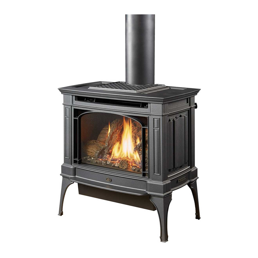
Featuring the
Berkshire Owner's Manual
Installer:
After installation give this manual to the home-owner and
explain operation of this heater.
Copyright 2007, T.I.
Burner
$10.00
100-01187_000
• Direct Vent Freestanding Stove
• Natural Gas or Propane
• Vent Horizontally or Vertically
• Standard Residential
• Mobile Home Approved
Tested and Listed by
OMNI-Test Laboratories, Inc.
Beaverton, Oregon
Report # 028-S-28-5
ANSI Z21.88
4800 Harbour Pointe Blvd. SW
4070219
Mukilteo, WA 98275
Advertisement
Table of Contents

Related Manuals for Lopi Berkshire


Summary of Contents for Lopi Berkshire
- Page 1 OMNI-Test Laboratories, Inc. Beaverton, Oregon Report # 028-S-28-5 Featuring the Burner ANSI Z21.88 Berkshire Owner's Manual Installer: After installation give this manual to the home-owner and explain operation of this heater. 4800 Harbour Pointe Blvd. SW Copyright 2007, T.I. $10.00...
-
Page 2: Introduction & Important Information
Introduction Introduction We welcome you as a new owner of a Lopi Berkshire stove. In purchasing a Berkshire you have joined the growing ranks of concerned individuals whose selection of an energy system reflects both a concern for the environment and aesthetics. The Berkshire is one of the finest home heaters the world over. -
Page 3: Table Of Contents
Table of Contents Introduction Operation Introduction & Important Information....2 Before You Begin .........28 Location of Controls ........28 Safety Precautions Starting The Pilot .........29 Safety Precautions ........4 Starting the Stove for the First Time ....30 Features & Specifications Turning the Stove On and Off ......30 Features ............6 Adjusting the Flame Height......30 Installation Options ........6... -
Page 4: Safety Precautions
Safety Precautions • IF YOU SMELL GAS: * Do not light any appliance * Extinguish any open flame * Do not touch any electrical switch or plug or unplug anything * Open windows and vacate building * Call gas supplier from neighbor's house, if not reached, call fire department •... - Page 5 Safety Precautions • Do not place clothing or • Light the heater using the other flammable items on or built-in piezo igniter. Do not near the heater. Because use matches or any other this heater can be controlled external device to light your by a thermostat there is a heater.
-
Page 6: Features
Specifications Features: Installation Options: Ember Fyre™ Burner for "Wood Fire" Look Freestanding Stove Works During Power Outages (millivolt system) Horizontal or Vertical Vent High Efficiency Optional Thermostat or Remote Control Residential or Mobile Home Optional Blower for Quicker Heat Distribution Straight or Corner Placement Convenient Operating Controls Variable-Rate Heat Output... -
Page 7: Installation
Installation (for qualified installers only) Installation Warnings: Failure to follow all of the requirements may result in property damage, bodily injury, or even death. This heater must be installed by a qualified installer who has gone through a training program for the installation of direct vent gas appliances. This appliance must be installed in accordance with all local codes, if any;... -
Page 8: Installation Hints
Installation (for qualified installers only) Installation Hints: If converting to LP, convert the appliance prior to installation. The blower is easiest to install prior to installation. Because the blower is located near the gas inlet location, the gas inlet must be routing around the blower position. Install the logs last - they are fragile. -
Page 9: Heater Placement Requirements
Installation (for qualified installers only) Heater Placement Requirements • Heater must be installed on a level surface capable of supporting the heater and vent. • Due to high temperatures, the appliance should be located out of traffic and away from furniture and draperies. -
Page 10: Gas Line Installation
Installation (for qualified installers only) Gas Line Installation MASSACHUSETTS INSTALLATIONS WARNING: THIS PRODUCT MUST BE INSTALLED BY A LICENSED PLUMBER OR GAS FITTER WHEN INSTALLED WITHIN THE COMMONWEALTH OF MASSACHUSETTS. OTHER MASSACHUSETTS CODE REQUIREMENTS: Flexible connector must not be longer than 36 inches. Shutoff valve must be a “T”... -
Page 11: Vent Requirements
Installation (for qualified installers only) Vent Requirements • The vent must maintain the required 1" clearance to combustible materials to prevent a fire. Do not fill air spaces with insulation. • The gas appliance and vent system must be vented directly to the outside of the building, and never be attached to a chimney serving a separate solid fuel or gas-burning appliance. -
Page 12: Approved Vent Configurations
Installation (for qualified installers only) Approved Vent Configurations Restrictor Position • A restrictor is built into the appliance to control the flow rate of exhaust gases. This ensures proper flames for the wide variety of vent configurations. Depending upon the vent configuration, you may be required to adjust the restrictor position. -
Page 13: Vertical Term. With 0, 2, Or 4 45° Elbows
Installation (for qualified installers only) Vertical Termination with Zero, Two, or Four 45° Elbows • The termination must fall within the shaded area shown in the chart. Use the indicated restrictor position. 40' (max) 40' (max) Restrictor • If using offsets, use the Position # 6 table below to calculate the vertical rise and horizontal... -
Page 14: Hor. Term. With 1 90° Elbow
Installation (for qualified installers only) Horizontal Termination with One 90° Elbow • If using a Snorkel Termination (14” or 36”) add the snorkel height to the vertical height (snorkel terminations are used primarily for basement installations). • The termination must fall within the shaded area shown in the chart. Use the indicated restrictor position. -
Page 15: Hor. Term. With 2 Elbows
Installation (for qualified installers only) Horizontal Termination with Two Elbows one 90° vertical and one 90° or 45° horizontal elbow • If using a Snorkel Termination (14” or 36”) add the snorkel height to the vertical height (snorkel terminations are used primarily for basement installations). •... -
Page 16: Hor. Term. With 3 Elbows
Installation (for qualified installers only) Horizontal Termination with Three 90° Elbows (all vertical) • The termination must fall within the shaded area shown in the chart. Use the indicated restrictor position. 21' (max) 21' (max) Restrictor Position # 5 NOTE: Restrictor positions are based 15 feet 15 feet... -
Page 17: Vertical Term. With 2 90° Elbows
Installation (for qualified installers only) Vertical Termination with Two 90° Elbows • The termination must fall within the shaded area shown in the chart. Use the indicated restrictor position. 40' (max) 40' (max) Restrictor Position # 6 35 feet 35 feet Restrictor Position # 5 30 feet... -
Page 18: Vertical Term. With 3 Elbows
Installation (for qualified installers only) Vertical Termination with Three 90° Elbows (Two 90° Vertical and One 45° or 90° Horizontal Elbow) • The termination must fall within the shaded area shown in the chart. Use the indicated restrictor position. 40' (max) 40' (max) Restrictor Position # 5... -
Page 19: Vent Termination Requirements
Installation (for qualified installers only) Vent Termination Requirements (see illustration below) Venting terminals shall not be recessed into a wall or siding. Minimum 9" clearance from any door or window Roof Minimum 12" above any grade, veranda, porch, deck or balcony Surface Minimum 3-3/8"... -
Page 20: Class A Chimney Conversion
Installation (for qualified installers only) Class A Chimney Conversion Kit Simpson Duravent provides a conversion kit for those wishing to use an existing wood stove chimney to vent this direct vent stove. The illustration below gives an overview of this type of installation. See the instructions included with the kit for details. -
Page 21: Masonry Chimney Conversion
Installation (for qualified installers only) Masonry Chimney Conversions (Interior or Standard) • Follow the requirements and use the equipment listed in the illustration below to install this appliance into an interior masonry chimney. • Maximum vertical rise is 40' • Minimum vertical rise is 10' •... -
Page 22: Finalizing The Installation
Finalizing the Installation (for qualified installers only) Finalizing the Installation Make sure the gas control valve is “OFF” and the heater is cool prior to conducting service. 1 Remove the face and glass (see page 24) We recommend you purge the gas line at this time (with the glass removed). This allows gas to be detected once it enters the firebox, ensuring gas does not build up. -
Page 23: Air Shutter Adjustment
Finalizing the Installation (for qualified installers only) Let the heater burn for thirty minutes. Adjust the air shutter, if necessary, to achieve the correct looking flame (see the illustration below). • The air shutter adjusts the amount of air that mixes with the gas before it exits the burner holes. It is used to fine-tune the flame for differences in altitude and vent configuration. -
Page 24: Glass Removal (& Installation)
Finalizing the Installation (for qualified installers only) Glass Removal Make sure the gas control valve is “OFF” and the heater is cool prior to conducting service. Open the two latches holding the glass frame in place - follow the directions shown below Lift the stove top off the stove and place it aside. - Page 25 Finalizing the Installation (for qualified installers only) Glass Frame Removal and Installation (continued) The latch can come loose from the latch assembly. This occurs only when it is rotated. Follow the directions below to re-install the latch if it comes loose. Hold the latch at an angle and insert it into the slot on the glass frame anchor.
-
Page 26: Log Installation
Finalizing the Installation (for qualified installers only) Log Installation Make sure the gas control valve is “OFF” and the heater is cool prior to conducting service. Failure to position the parts in accordance with these diagrams or failure to use only parts specifically approved with this appliance may result in property damage or personal injury. - Page 27 Finalizing the Installation (for qualified installers only) Log Installation (continued) Place the top twigs in place. Note how the holes in the bottom of the twigs fit over the pins on the logs. Place the front twigs in place. They fit on the flat portions of the burner.
-
Page 28: Before You Begin
Operation Before You Begin Warning: Read this entire manual before you use your new stove (especially the section "Safety Precautions" on pages 4 & 5). Failure to follow the instructions may result in property damage, bodily injury, or even death. Warning : Do not operate appliance with the glass front removed, cracked or broken. -
Page 29: Starting The Pilot
Operation Starting The Pilot Flame The pilot flame is required to ignite the main burners (it also plays a safety role). It should be left on once lit. It will stay lit unless the gas control valve is turned to "OFF". However, the pilot will go out if the gas is shut off, the propane tank runs out (or low) or if the stove malfunctions. -
Page 30: Starting The Stove For The First Time
Operation Starting the Stove for the First Time Fumes from the Painted Surfaces Curing Burn the heater at a medium setting for approximately one hour the first time. This will cure the painted surfaces. Fumes from the paint curing and oil burning off the steel may occur. This is normal. -
Page 31: Adjusting The Blower Speed (Optional)
Operation Adjusting the Blower Speed (optional) The blower helps transfer heat from the heater into the room. It will not turn on until the heater is up to temperature (approximately 10 minutes after starting). See the illustration below for instructions on adjusting the blower speed. -
Page 32: Maintenance
Maintenance (for qualified service personnel only) Maintaining Your Stove's Appearance WARNING : Make sure the appliance has fully cooled prior to cleaning. Painted Surfaces • Painted surfaces should be cleaned with a duster. If scratches occur, lightly sand the area with fine sandpaper. Clean the area and, with the stove cool, apply one or two thin coats of stove paint to the area (mask the area to avoid overspray). -
Page 33: Troubleshooting Table
Maintenance (for qualified service personnel only) Troubleshooting Table Problem: Possible Cause: Don't Call for Service Until You: A gas shut off valve is turned off Check all gas shut off valves Pilot Will Not Light The gas control knob isn't turned to "PILOT" See "Starting the Pilot Light"... -
Page 34: How This Stove Works
Maintenance (for qualified service personnel only) How this Stove Works This stove was designed with safety as the primary concern. Many of the components inside this stove are for safety purposes. Therefore, only certified gas service technicians should service this stove. -
Page 35: Wiring Diagram
Maintenance (for qualified service personnel only) Wiring Diagram Caution: Label all wires prior to disconnection when servicing controls. Wiring errors can cause improper and dangerous operation. Verify proper operation after servicing. Thermocouple Thermopile Piezo Igniter Millivolt Wiring On/Off Switch (for gas control valve) Brown Copper Co-Axial Wire... -
Page 36: Safety (Listing) Label
Safety Label A copy of the safety (listing) label (adhered to the back of the stove) is shown below. Berkshire Vented Gas Fireplace Heater Report No. 028-S-28-5 Certified for USA & Canada Tested to: ANSI Z21.88b-1999/CSA 2.33-M99 “Vented Gas Fireplace Heater”, CAN/CGA 2.17-M91 “Gas-Fired Appliances for use at High Altitudes”, and UL307b-1995 “Gas Burning Heating Appliances for Manufactured Homes”... -
Page 37: Warranty
Limited 7 Year Warranty To register your TRAVIS INDUSTRIES, INC. 7 Year Warranty, complete the enclosed warranty card and mail it within ten (10) days of the appliance purchase date to: TRAVIS INDUSTRIES, INC., 4800 Harbour Pointe Blvd. SW, Mukilteo, WA 98275. TRAVIS INDUSTRIES, INC. warrants this gas appliance (appliance is defined as the equipment manufactured by Travis Industries, Inc.) to be defect-free in material and workmanship to the original purchaser from the date of purchase as follows: Check with your dealer in advance for any costs to you when arranging a warranty call. -
Page 38: Lp Conversion Kit
Optional Equipment (for qualified installers only) LP Conversion Instructions Install the conversion kit prior to installing the gas line to ensure proper gas use. Remove the face and glass (see page 24). Remove the logs and coals (if installed - page 26) Remove the burner (see illustration below). -
Page 39: Optional Equipment
Optional Equipment (for qualified installers only) Follow the directions below to replace the orifice. Remove the four screws holding the mixing tube in place. 1/4" Nutdriver Remove the mixing tube from the air shutter by sliding it to the left. Air Shutter Slide the air shutter to the fully open position. - Page 40 Optional Equipment (for qualified installers only) Remove and discard the three screws using a Install the logs and slotted screwdriver of Torx T-20. embers. Replace glass and face. Remove the regulator from the front of the gas Remove and discard the control valve.
-
Page 41: Blower
Optional Equipment (for qualified installers only) Blower (SKU 99000153) WARNING: Turn the gas control valve to off and make sure the appliance has fully cooled prior to conducting service. Attach the two black wires at the rear right of the stove to the thermodisk (orientation does not matter). Then attach the thermodisk to the bottom of the stove body following the directions below. - Page 42 Optional Equipment (for qualified installers only) Slide the left side of the blower mounting bracket over the grommets on the left mounting bracket attached to the stove (see the illustration below). Then insert the stud plate through the right side grommets and through the right mounting bracket on the stove.
-
Page 43: Accent Light
Optional Equipment (for qualified installers only) Accent Light (Type 2 – 94400111) Make sure power to the heater has been turned off prior to installation (unplug the power cord). Do not connect 110-120 VAC to the gas control valve or the on/off circuit on this fireplace. IMPORTANT INSTALLATION NOTE FOR MODELS USING THE FIREBACKS: Follow the steps below if installing the firebacks with an accent light. - Page 44 Optional Equipment (for qualified installers only) Attach the rheostat assembly following the directions below. Attach the quick- connect from the accent light to the quick-connect on the rheostat wiring harness. Use the included wire nut to connect the wire leading from the rheostat to the remaining wire leading from the accent light.
- Page 45 Optional Equipment (for qualified installers only) Accent Light Operation HIGH Turn the dial all the Turn the dial 180° The high position way counter-clockwise clockwise until the light is all the way until it clicks off. begins to glow. clockwise. N O T E : The accent light responds best when turned to high, then turned down to the desired light level.
-
Page 46: Cast Or Stone Inserts
Optional Equipment (for qualified installers only) Cast or Stone Inserts WARNING : Turn the gas control valve to off and make sure the appliance has fully cooled prior to conducting service. Lift the stove top and place it upside down on a smooth, non-scratching surface. Install the stone inserts into the stove top following the directions below. - Page 47 Optional Equipment (for qualified installers only) Install the side inserts following the directions below. Loosen the rear screw holding the side Side Insert Retainer insert retainers in place (both sides). Remove the front screw holding the side insert retainers in place (both 3/8"...
-
Page 48: Index
Index Accent Light.............43 Installation Options ...........6 Adjusting the Blower Speed......31 Items Required for Installation......7 Adjusting the Flame Height .......30 Leaking Gas ......See Inst. on Cover Air Shutter Adjustment........23 Listing Information ..........36 Altitude Considerations........10 Location of Controls..........28 Approved Vent Configurations......13-18 Log Set Installation and Removal .......26 Blower Control..........31 Maintenance ............32 BTU Input............6...