Table of Contents
Advertisement
www.travisproducts.com
4800 Harbour Pointe Blvd. SW
Mukilteo, WA 98275
WARNING:
If the information in these instructions is not followed exactly, a fire or explosion may
result causing property damage, personal injury or loss of life.
-
Do not store or use gasoline or other flammable vapors and liquids in the vicinity of this or any other
appliance.
WHAT TO DO IF YOU SMELL GAS:
• Do not try to light any appliance.
• Do not touch any electrical switch; do not use any phone in your building.
• Immediately call gas supplier from a neighbor's phone. Follow the gas supplier's instructions.
• If you cannot reach your gas supplier, call the fire department.
-
Installation and service must be performed by a qualified installer, service agency or the gas supplier.
This appliance may be installed in an aftermarket permanently located, manufactured home (USA only) or mobile home, where
not prohibited by local codes.
This appliance is only for use with the type(s) of gas indicated on the rating plate. A conversion kit is supplied with the appliance.
¤ Copyright 2013, T.I.
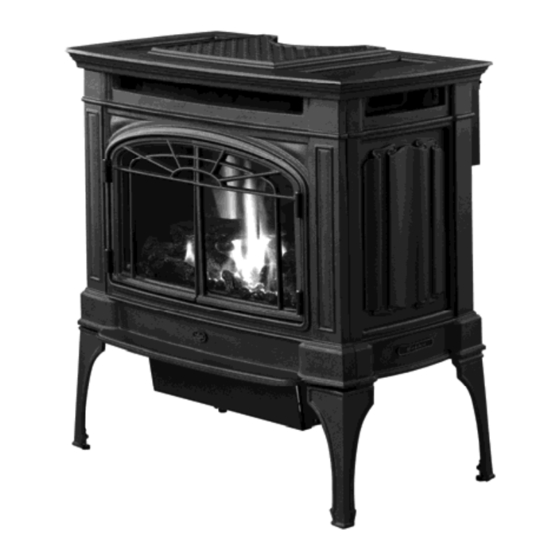
• Direct Vent Freestanding Stove
• Natural Gas or Propane
• Vent Horizontally or Vertically
• Standard Residential
• Mobile Home Approved
Berkshire
Owner's Manual
Featuring the
Tested and Listed by
Omni-Test Laboratories, Inc.
$10.00
100-01314
Burner
Portland, Oregon
ANSI Z21.88
Installer:
After installation give this manual to the
homeowner and explain operation of this
heater.
Consumer:
Retain this manual for future reference.
4121129
2
Advertisement
Table of Contents

Related Manuals for Lopi Berkshire GS2


Summary of Contents for Lopi Berkshire GS2
- Page 1 • Direct Vent Freestanding Stove • Natural Gas or Propane • Vent Horizontally or Vertically • Standard Residential • Mobile Home Approved Berkshire Owner’s Manual Featuring the Burner Tested and Listed by Omni-Test Laboratories, Inc. Portland, Oregon www.travisproducts.com 4800 Harbour Pointe Blvd. SW ANSI Z21.88 Mukilteo, WA 98275 WARNING:...
-
Page 2: Introduction
Introduction Introduction We welcome you as a new owner of a Lopi Berkshire GS2 stove. In purchasing a Berkshire you have joined the growing ranks of concerned individuals whose selection of an energy system reflects both a concern for the environment and aesthetics. The Berkshire is one of the finest home heaters the world over. -
Page 3: Table Of Contents
Table of Contents Introduction ..........2 Face and Glass Removal ......25 Important Information ........2 Log Installation ........... 27 Ember Placement ..........27 Listing Details ..........2 Rear Log Placement ..........27 IAS (ICBO) Approval..........2 Left Log Placement ..........28 Features: ..............6 Right Log Placement ..........28 Installation Options: ..........6 Right Twig Placement..........29... -
Page 4: If You Smell Gas
Safety Precautions • IF YOU SMELL GAS: * Do not light any appliance * Extinguish any open flame * Do not touch any electrical switch or plug or unplug anything * Open windows and vacate building * Call gas supplier from neighbor's house, if not reached, call fire department •... - Page 5 Safety Precautions Do not place clothing or other Light the heater using the built- • • flammable items on or near the in igniter. Do not use matches heater. Because this heater or any other external device to can be controlled by a light your heater.
-
Page 6: Features
Specifications Features: Installation Options: Freestanding Stove Ember Fyre™ Burner for "Wood Fire" Look Works During Power Outages (battery backup system) Horizontal or Vertical Vent High Efficiency Residential or Mobile Home Optional Thermostat or Remote Control Optional Blower for Quicker Heat Distribution Straight or Corner Placement Convenient Operating Controls Bedroom Approved... -
Page 7: Packing List
Installation (for qualified installers only) Installation Warnings Failure to follow all of the requirements may result in property damage, bodily injury, or even death. This heater must be installed by a qualified installer who has gone through a training program for the installation of direct vent gas appliances. -
Page 8: Stove Clearances
Installation (for qualified installers only) Installation Hints If converting to LP, convert the appliance prior to installation. Install the logs last - they are fragile. When determining the location of the stove, locate the wall studs (for horizontal penetrations) and ceiling trusses (for vertical penetrations). -
Page 9: Heater Placement Requirements
Installation (for qualified installers only) Heater Placement Requirements Heater must be installed on a level surface capable of supporting the heater and vent. • Due to the high temperature, the heater should be located out of traffic and away from furniture •... -
Page 10: Optional Wall Switch Or Thermostat Installation
Installation (for qualified installers only) Optional Wall Switch or Thermostat Installation Do not connect 110-120 VAC to the gas control valve or wiring system of this stove. The switch must be installed by a qualified installer. Label all wires prior to disconnection when servicing controls. Wiring errors can cause Caution: improper and dangerous operation. -
Page 11: Gas Line Installation
Installation (for qualified installers only) Gas Line Installation DO NOT CONNECT THIS UNIT TO A CHIMNEY FLUE SERVING ANOTHER APPLIANCE. The gas line must be installed in accordance with all local codes, if any; if not, follow current ANSI Z223.1 or NFPA 54 in the USA and the current CGA B149 in Canada. The heater and gas control valve must be disconnected from the gas supply piping during any pressure testing of that system at test pressures in excess of 1/2 psig (3.45 kPA). -
Page 12: Vent Requirements
Installation (for qualified installers only) Vent Requirements The gas appliance and vent system must be vented directly to the outside of the building, and never • be attached to a chimney serving a separate solid fuel or gas-burning appliance. Each direct vent gas appliance must use its own separate vent system. -
Page 13: Approved Vent Configurations
Installation (for qualified installers only) Approved Vent Configurations Restrictor Position A restrictor is built into the appliance to control the flow rate of exhaust gases. This ensures • proper flames for the wide variety of vent configurations. Depending upon the vent configuration, you may be required to adjust the restrictor position. -
Page 14: Vertical Terminations With Zero, Two, Or Four 45° Elbows
Installation (for qualified installers only) Vertical Terminations with Zero, Two, or Four 45° Elbows 10’ (3.1M) Minimum • System Height (with or without offsets) 40’ (12.2M) Maximum • System Height 24’ (7.3M) Maximum Offset • The termination must fall • within the shaded area shown in the chart. -
Page 15: Horizontal Termination With One 90° Elbow
Installation (for qualified installers only) Horizontal Termination with One 90° Elbow If using a Snorkel Termination (14” (356mm) or 36” (915mm)) add the snorkel height to the vertical • height (snorkel terminations are used primarily for basement installations). The termination must fall within the shaded area shown in the chart. Use the indicated restrictor •... -
Page 16: Horizontal Termination With Two Elbows (One 90° Vertical And One 90° Or 45° Horizontal Elbow)
Installation (for qualified installers only) Horizontal Termination with Two Elbows one 90° vertical and one 90° or 45° horizontal elbow If using a Snorkel Termination (14” (356mm) or 36” (915mm)) add the snorkel height to the vertical • height (snorkel terminations are used primarily for basement installations). The termination must fall within the shaded area shown in the chart. -
Page 17: Horizontal Termination With Three 90° Elbows (All Vertical)
Installation (for qualified installers only) Horizontal Termination with Three 90° Elbows (all vertical) If using a Snorkel Termination (14” (356mm) or 36” (915mm)) add the snorkel height to the vertical • height (snorkel terminations are used primarily for basement installations). The termination must fall within the shaded area shown in the chart. -
Page 18: Vertical Terminations With Two 90° Elbows
Installation (for qualified installers only) Vertical Terminations with Two 90° Elbows The termination must fall within the shaded area shown in the chart. Use the indicated restrictor • position. © Travis Industries 4121129 100-01314... -
Page 19: Vertical Terminations With Three 90° Elbows (Two 90° Vertical And One 45° Or 90° Horizontal Elbow)
Installation (for qualified installers only) Vertical Terminations with Three 90° Elbows (Two 90° Vertical and One 45° or 90° Horizontal Elbow) The termination must fall within the shaded area shown in the chart. Use the indicated restrictor • position. © Travis Industries 4121129 100-01314... -
Page 20: Vent Termination Requirements (See Illustration Below)
Installation (for qualified installers only) Vent Termination Requirements (see illustration below) Venting terminals shall not be recessed into a wall or siding. Minimum 9" (229mm) clearance from any door or window Minimum 12" (305mm) above any grade, veranda, porch, deck or balcony Minimum 1"... -
Page 21: Class A Chimney Conversion Kit
Installation (for qualified installers only) Class A Chimney Conversion Kit Simpson Duravent provides a conversion kit for those wishing to use an existing wood stove chimney to vent this direct vent stove. The illustration below gives an overview of this type of installation. See the instructions included with the kit for details. -
Page 22: Interior Masonry Chimney Conversions
Installation (for qualified installers only) Interior Masonry Chimney Conversions Follow the requirements and use the equipment listed in the illustration below to install this appliance • into an interior masonry chimney. Maximum vertical rise is 40' (12M) • Minimum vertical rise is 10' (3M) •... -
Page 23: Steps For Finalizing The Installation
Installation (for qualified installers only) Steps for Finalizing the Installation 1. Remove the glass (see page 25). NOTE: If using propane (LP) convert the appliance prior to installing the logs. 2. We recommend you purge the gas line at this time (with the glass removed). This allows gas to be detected once it enters the firebox, ensuring gas does not build up. -
Page 24: Air Shutter Adjustment
Installation (for qualified installers only) 5. Install the logs (see page 27). 6. Replace the glass. 7. Start the heater. 8. Leak test all gas joints. 9. Check the air shutter following the directions below. Air Shutter Adjustment Let the heater burn for fifteen minutes (make sure the logs and glass are in place). The flames should be yellow with no sooting. -
Page 25: Travis Industries
Finalizing the Installation (for qualified installers only) Face and Glass Removal Make sure the gas control valve is “OFF” and the heater is cool prior to conducting service. © Travis Industries 4121129 100-01314... - Page 26 Finalizing the Installation (for qualified installers only) Glass Frame Removal and Installation (continued) The latch can come loose from glass frame anchor. This occurs when it is turned 1/4 turn when it is disengaged. Follow the directions below to re-install the latch if it becomes loose. ©...
-
Page 27: Log Installation
Finalizing the Installation (for qualified installers only) Log Installation The logs are fragile, especially after being exposed to heat. • Make sure the gas control valve is “OFF” and the heater is cool prior to conducting service. • Failure to position the parts in accordance with these diagrams or failure to use only parts specifically approved with this appliance may result in property damage or personal injury. -
Page 28: Left Log Placement
Finalizing the Installation (for qualified installers only) Left Log Placement The left log has two holes on the bottom. Place the log so the pin on the burner and the metal bracket insert into the holes on the log (see photos below). Right Log Placement The right log has two holes on the bottom. -
Page 29: Right Twig Placement
Finalizing the Installation (for qualified installers only) Right Twig Placement The right twig has a single hole in the bottom that fits over the right pin on the back log (see photos below). The lower side of the twig rests on the right log. Place the twig as shown below. Left Twig Placement The left twig has two holes in the bottom of it –... -
Page 30: Front Ember Chunk Placement
Finalizing the Installation (for qualified installers only) Front Ember Chunk Placement Left Ember Chunk Center Ember Chunk Right Ember Chunk Place the ember chunks as shown in the photos below. Make sure the ember chunks do not cover any burner holes. Right Side Ember Chunk Center Ember Chunk Left Side Ember Chunk... -
Page 31: Before You Begin
Operation Before You Begin Warning: Read this entire manual before you use your new stove (especially the section "Safety Precautions" on pages 4 & 5). Failure to follow the instructions may result in property damage, bodily injury, or even death. Warning: Do not operate appliance with the glass front removed, cracked or broken. -
Page 32: Starting The Stove For The First Time
Operation Starting the Stove for the First Time Burn the heater at a high setting with the blower off for an extended period (up to 48 hours). This will cure the painted surfaces. Fumes from the paint curing and oil burning off the steel will occur. This is normal. -
Page 33: Accent Light
Operation Accent Light This stove has a built-in accent light that may be turned on and off and dimmed to your preference. Turn the knob to achieve the desired light output. Adjusting the Optional Blower Speed The blower helps transfer heat from the heater into the room. It will not turn on until the heater is up to temperature (approximately 15 minutes after starting). -
Page 34: Normal Operating Sounds
Operation Normal Operating Sounds Normal Operating Odors This appliance has several areas that reach high temperatures. Dust or other particles on these areas may burn and create a burnt-paper smell. This is normal during startup. You may notice the smell is more acute if the appliance was left idle for a long period. -
Page 35: Maintaining Your Stove's Appearance
Maintenance (for qualified service personnel only) Maintaining Your Stove's Appearance Painted Surfaces Painted surfaces should be cleaned with a duster. If scratches occur, lightly sand the area with fine • sandpaper. Clean the area and, with the stove cool, apply one or two thin coats of stove paint to the area (mask the area to avoid overspray). -
Page 36: Accent Light Replacement
Maintenance (for qualified service personnel only) Accent Light Replacement An accent light is included in your stove to provide additional lighting. This bulb will burn out over time. To replace, follow the directions below: Shut off gas to the stove and let it cool for 15 minutes. ... -
Page 37: Troubleshooting Table
Maintenance (for qualified service personnel only) Troubleshooting Table Problem: Possible Cause: Don't Call for Service Until You: Main Burners Will The ON/OFF switch is turned to "OFF" Turn the ON/OFF switch to "ON" The remote control is not working correctly See the remote control instructions Not Start The thermostat is disconnected or set too low... -
Page 38: Safety Label
Safety Label Safety Label The safety (listing) label is on the back of the stove. A copy is shown below. L.P. N.G. 31,000 31,000 12,600 10,700 2012 2013 2014 © Travis Industries 4121129 100-01314... -
Page 39: Conditions & Exclusions
Warranty Register your TRAVIS INDUSTRIES, INC. Limited 7 Year Warranty online at traviswarranty.com, or complete the enclosed Warranty card and mail it within ten (10) days of the appliance purchase date to: TRAVIS INDUSTRIES, INC., 4800 Harbour Pointe Blvd. SW, Mukilteo, WA 98275. TRAVIS INDUSTRIES, INC. warran ts this gas appliance (appliance is defined as the equipment manufactured by Travis Industries, Inc.) to be defect-free in material and workmanship to the original purchaser from the date of purchase as follows: Check w ith your dealer in adv ance for any costs to you w hen arranging a w arranty call. -
Page 40: Lp Conversion Instructions
Optional Equipment (for qualified installers only) LP Conversion Instructions WARNING This conversion kit shall be installed by a qualified service agency in accordance with the manufacturer’s instructions and all applicable codes and requirements of the authority having jurisdiction. If the information in these instructions is not followed exactly, a fire, explosion or production of carbon monoxide may result causing property damage, personal injury or loss of life. - Page 41 Optional Equipment (for qualified installers only) Follow the directions below to replace the orifices. Rear Burner Orifice Front Burner Orifice Thread Sealant 15/16" 24mm 1/2" Wrench Orifice ID ORIFICE SIZE Natural Gas LP (Propane) Front Burner Orifice #50 DMS #58 DMS Rear Burner Orifice #47 DMS #56 DMS...
- Page 42 Optional Equipment (for qualified installers only) Remove and discard the NG air deflector. Attach the LP air deflector included with the stove. Note how the LP deflector has a notch along the bottom. NG Air Deflector LP Air Deflector Install the LP pilot orifice following the directions below. (a) Use a 7/16”...
- Page 43 Optional Equipment (for qualified installers only) Remove and discard the screws (see “a” below) holding the stock regulator in place (see “b” below). Remove the stock regulator and gasket (see “c” below). Place the LP regulator in place, making sure the pre-fitted gasket (see “c”...
-
Page 44: Gs2 Remote Installation
Optional Equipment (for qualified installers only) GS2 Remote Installation Packing List Transmitter Battery Box Remote Wall Mount with Attachment Screws and Anchors Stepper Motor Torx Wrench Remote Control DVD GSR2 IFC Split-flow Harness (attached to IFC) ... -
Page 45: Base Wiring Diagram
Optional Equipment (for qualified installers only) Base Wiring Diagram Caution: Label all wires prior to disconnection when servicing controls. Wiring errors can cause improper and dangerous operation. 2.5 Amp Accessory Fuse Power Accent Accent Light (s) Light Rheostat Blower 120 VAC Hookup Power In Appliance... -
Page 46: Gs2 Remote Wiring Diagram
Optional Equipment (for qualified installers only) GS2 Remote Wiring Diagram Accessory Power White Black Black White Accent Light (s) Optional Blower(s) 120 VAC Power In 2.5 Amp Fuse 2.5 Amp Fuse Appliance Ground 3.15A FUSE Integrated Pilot Sensor Fireplace Flame Control Detect (IFC) -
Page 47: Installation
Optional Equipment (for qualified installers only) Installation 1. Remove the Comfort Control–Battery Plate from the control panel (keep the screws). 2. Remove the control panel and place face-down in front of the heater (keep the screws). 3. Disconnect the comfort control and battery backup wires. 4. - Page 48 Optional Equipment (for qualified installers only) 5. Remove the rear panel from the heater and set aside. It is held in place with seven screws. Screw Locations 6. Disconnect input power. 7. Pull the base IFC to the rear of the stove to access the wiring (it is held in place with Velcro). ©...
- Page 49 Optional Equipment (for qualified installers only) 8. Disconnect the following: Main harness Power (3 wires) Pilot connections (slide silicone tubing up) On/Off wires 9. Remove and place aside the base IFC (it may be kept for spare parts). 10. Remove the on/off switch by prying it out. Disconnect the wires. 11.
- Page 50 Optional Equipment (for qualified installers only) 12. Remove and discard the screws (see “a” below) holding the stock regulator in place (see “b” below). Remove and discard the stock regulator, spring, and gasket (see “c” below). 13. The stepper motor (adjustable regulator) has an installation sheet included with it – make sure to follow all of the directions.
-
Page 51: Wiring The Blower To The Gsr2
Optional Equipment (for qualified installers only) Instructions for Using the Optional Blower with GS2 Remote When using the GreenSmart™ 2 remote, the power for the blower will be routed through the fuse and IFC, bypassing the rheostat and snap disc included with the blower kit. Order of Installation Install the blower assemblies with the IFC removed (see instructions included with the blower for details). -
Page 52: Order Of Installation
Optional Equipment (for qualified installers only) 14. Wire the accent light for remote operation. When using the GreenSmart™ 2 remote, the power for the accent light(s) will be routed through the fuse and IFC, bypassing the rheostat. Order of Installation Connect the wiring with the IFC removed as shown below. - Page 53 Optional Equipment (for qualified installers only) 16. Attach the following: (Black) (White) (Green) Pilot connections Power (3 wires – make sure orientation is correct) Comfort Control connection Make sure silicone tubing is pushed down Main Harness Stepper Motor © Travis Industries 4121129 100-01314...
- Page 54 Optional Equipment (for qualified installers only) 17. Disconnect the IPI/CP switch from IPI/CP wires. Attach one of the jumper wires to the two wires. Discard the IPI/CP switch. 18. Remove the IPI/CPI switch and place aside (may be kept for spare parts). 19.
- Page 55 Optional Equipment (for qualified installers only) 20. Connect the battery box power molex connector to the main harness molex connector. 21. Route the battery box harness through the control panel and attach to the battery box. 22. Place the IFC in location inside the heater and attach using the supplied velcro tape. 23.
- Page 56 Optional Equipment (for qualified installers only) 24. Re-attach the control panel. 25. Attach the battery box to the control panel using the screws removed in step 2. © Travis Industries 4121129 100-01314...
- Page 57 Optional Equipment (for qualified installers only) 26. Re-connect the input power. 27. Replace the rear panel and restore the stove to the correct configuration (turn on power and gas). See the instructions included with the remote for synchronizing the remote and the operating instructions. ©...
-
Page 58: Index
Index Index Accent Light ..........33 Installation Overview ........7 Accent Light Replacement ......36 Installation Warnings........7 Additional Accessories Required......7 Interior Masonry Chimney Conversions ..22 Additional Items Required .......7 Introduction ............2 Adjusting the Flame Height......32 Listing Details ..........2 Adjusting the Optional Blower Speed ..... 33 Location of Controls ........