MTD 400 Operator's Manual
Rear tine crt tiller
Hide thumbs
Also See for 400:
- Operator's manual (56 pages) ,
- Owner's manual (20 pages) ,
- Manual (6 pages)
Table of Contents
Advertisement
Available languages
Available languages
Safe Operation Practices • Set-Up • Operation • Maintenance • Service • Troubleshooting • Warranty
O
'
M
peratOr
s
anual
Rear Tine CRT Tiller — 400
WARNING
READ AND FOLLOW ALL SAFETY RULES AND INSTRUCTIONS IN THIS MANUAL
BEFORE ATTEMPTING TO OPERATE THIS MACHINE.
FAILURE TO COMPLY WITH THESE INSTRUCTIONS MAY RESULT IN PERSONAL INJURY.
MTD LLC, P.O. BOX 361131 CLEVELAND, OHIO 44136-0019
Printed In USA
Form No. 769-04436
(October 16, 2008)
Advertisement
Table of Contents

Related Manuals for MTD 400


Summary of Contents for MTD 400
- Page 1 READ AND FOLLOW ALL SAFETY RULES AND INSTRUCTIONS IN THIS MANUAL BEFORE ATTEMPTING TO OPERATE THIS MACHINE. FAILURE TO COMPLY WITH THESE INSTRUCTIONS MAY RESULT IN PERSONAL INJURY. MTD LLC, P.O. BOX 361131 CLEVELAND, OHIO 44136-0019 Printed In USA Form No. 769-04436...
-
Page 2: Table Of Contents
Choose from the options below: ◊ Visit us on the web at www.mtdproducts.com ◊ Call a Customer Support Representative at (800) 800-7310 or (330) 220-4683 ◊ Write us at MTD LLC • P.O. Box 361131 • Cleveland, OH • 44136-0019... -
Page 3: Safe Operation Practices
Important Safe Operation Practices WARNING! This symbol points out important safety instructions which, if not followed, could endanger the personal safety and/or property of yourself and others. Read and follow all instructions in this manual before attempting to operate this machine. Failure to comply with these instructions may result in personal injury. - Page 4 When practical, remove gas-powered equipment After striking a foreign object, stop the engine, disconnect from the truck or trailer and refuel it on the ground. the spark plug wire and ground against the engine. If this is not possible, then refuel such equipment on Thoroughly inspect the machine for any damage.
- Page 5 If the fuel tank has to be drained, do this outdoors. Spark Arrestor Observe proper disposal laws and regulations for gas, oil, WARNING! This machine is equipped with an etc. to protect the environment. internal combustion engine and should not be used According to the Consumer Products Safety Commission on or near any unimproved forest-covered, (CPSC) and the U.S.
- Page 6 Safety Symbols This page depicts and describes safety symbols that may appear on this product. Read, understand, and follow all instructions on the machine before attempting to assemble and operate. Symbol Description READ THE OPERATOR’S MANUAL(S) Read, understand, and follow all instructions in the manual(s) before attempting to assemble and operate WARNING—...
-
Page 7: Assembly & Set-Up
Assembly & Set-Up Contents of Carton • One Tiller • One Operator’s Manual • One Handlebar Assembly • Bottle Oil WARNING! To prevent personal injury or property damage, do not start the engine until all assembly steps are complete and you have read and understand the Safe Operation Practices Section and the Operating Section in this manual. - Page 8 Snap the cable housing clips into the handle Click Pin assembly cable mount as seen here. The red clip (reverse cable) fits into the top position on the handle assembly, while the black clip (forward/clutch cable) feeds into the lower position on the handle assembly.
- Page 9 Note: Recommended oil to use in the future is 10W-30, with Transmission/Gear Oil a minimum classification of SF/SG), added to the unit until The transmission was filled with gear oil at the factory. However, the oil level registers between high (H) and low (L) on the you should check the gear oil level at this time to make certain it dipstick.
-
Page 10: Controls & Features
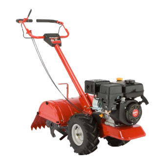
Controls and Features Reverse Handle Forward Clutch Bail & Tine Engagement Fuel Cap Oil Fill Cap Muffler & Dipstick Depth Regulator Air Filter Handle Height Adjustment Choke Rear Tine Shield Throttle Side Shield Tines Pull Starter Handle Wheel Drive Pin Oil Drain Figure 4-1 WARNING:... -
Page 11: Reverse Handle
Muffler Rear Tine Shield Engine exhaust exits the engine via the muffler. The rear tine shield protects the operator from flying debris while also smoothing out freshly tilled soil. Fuel Cap Side Shield Unscrew the fuel cap to add gasoline to the fuel tank . This unit runs on regular gas. -
Page 12: Operation
Operation WARNING: Starting And Stopping Before operating your machine, carefully read and understand this manual and all of Pre-Start Checklist its safety, operating and maintenance sections and instructions, along with all of the decals on the With the spark plug wire disconnected from the spark plug, machine. -
Page 13: Stopping The Engine
Put the throttle control lever located on the engine in the Setting The Depth “FAST” or “Rabbit” position. Tilling depth is controlled by the depth stake which can be Move the Choke into the Choke position. adjusted to five different settings. Adjust the side shields as you Put one hand on the fuel tank to stabilize the tiller when adjust the depth stake. - Page 14 Adjusting the Handle Height Tilling Tips & Techniques The handle should be adjusted so that when the tiller is digging Tilling Depth 3-4” into the soil, the handle falls to about waste-high. To adjust WARNING! Before tilling, contact your telephone handle, simply loosen the handle adjustment crank, move the or utilities company and inquire if underground handle to the desired height and retighten the adjustment crank.
- Page 15 Choosing Correct Wheel & Tine Speeds • If the garden size will not permit lengthwise and then crosswise tilling, then overlap the first passes by one-half With experience, you will find the tilling depth and tilling speed a tiller width, followed by successive passes at one-quarter combination that is best for your garden.
- Page 16 Terrace Gardening • Position the loading vehicle so that the ramp angle is as flat as possible (the less incline to the ramp, the better). Turn To create a terrace, start at the top of the slope and work the vehicle’s engine off and apply the parking brake. down.
-
Page 17: Maintenance & Adjustments
Maintenance & Adjustments Maintenance Schedule Check Before Every Every Every After first Engine each use 5 Hours 10 Hours 30 Hours 2 hours Manual Check Motor Oil Level Clean Engine Check Drive Belt Tension Check Nuts and Bolts Change Motor Oil Lubricate Tiller Service Engine Air Cleaner System Check Gear Oil Level in Transmission... - Page 18 Transmission Gear Oil Lubrication Check the transmission gear oil after every 30 hours of operation After every 10 operating hours, oil or grease the lubrication or whenever you notice any oil leak. Operating the tiller when points shown in Fig. 6-2 and described below. the transmission is low on oil can result in severe damage.
- Page 19 Off-Season Storage When the tiller won’t be used for an extended period, prepare it for storage as follows: Clean the tiller and engine. Do routine tiller lubrication and check for loose parts and hardware. Protect the engine and perform the recommended engine maintenance by following the storage instructions found in the Engine Maintenance section.
-
Page 20: Engine Maintenance
Engine Maintenance Maintenance Schedule Each Use or Every Season Every Season Every Season Service First 5 Hours Every 5 Hrs. or 25 Hours or 50 Hours or 100 Hours Dates Check Engine Oil Level Change Engine Oil Check Air Cleaner Service Air Cleaner Check Spark Plug Replace Spark Plug... -
Page 21: Air Filter
Air Filter Paper filters cannot be cleaned and must be replaced once a year or every 100 operating hours; more often if used in extremely dusty conditions. WARNING! Never use gasoline or low flash point solvents for cleaning the air cleaner element. A fire or explosion could result. - Page 22 NOTE: When installing a new spark plug, tighten 1⁄2 turn after the spark plug seats to compress the washer. When reinstalling a used spark plug, tighten 1⁄8-1⁄4 turn after the spark plug seats to compress the washer. CAUTION! The spark plug must be securely tightened.
- Page 23 Off-Season Storage Engines stored between 30 and 90 days need to be treated with a gasoline stabilizer and engines stored over 90 days need to be drained of fuel to prevent deterioration and gum from forming in fuel system or on essential carburetor parts. If the gasoline in your engine deteriorates during storage, you may need to have the carburetor, and other fuel system components, serviced or replaced.
-
Page 24: Service
Service Belt Replacement If the drive belt or auger belts need to be replaced, it is best to replace both belts at the same time. Use only a factory- authorized belt as an “over- the-counter” belt may not perform satisfactorily. The procedure requires average mechanical ability and commonly available tools. - Page 25 Remove the hex bolt securing the transmission drive Remove pulley pulley, then remove the pulley along with the two belts. Remove hex bolt with belts See Fig. 8-5. Replace the old belts with the new belts in the same order they were removed.
-
Page 26: Troubleshooting
Troubleshooting Problem Cause Remedy Engine does not start Spark plug wire disconnected. Reconnect wire. Engine Throttle Control Lever incorrectly set. Put lever in START position. Fuel tank empty. Add fuel. Stale gasoline. Drain fuel and add fresh fuel. Dirty air filter. Clean or replace filter (see Engine Maintenance section). -
Page 27: Replacement Parts
Replacement Parts Component Part Number and Description 1916658 Reverse V-Belt 1916657 Forward V-Belt 946-04506 Forward Drive Cable 946-04504 Reverse Drive Cable 642-04072 4-Point Tine Assembly (RH) 642-04071 4-Point Tine Assembly (LH) 711-0415 Clevis Pin, .375 x 1.75 714-0149B Internal Cotter Pin 934-04232 Wheels, 13 x 5 x 6 951-10292... -
Page 28: Warranty
MANUFACTURER’S LIMITED WARRANTY FOR The limited warranty set forth below is given by MTD LLC with c. Service completed by someone other than an authorized service respect to new merchandise purchased and used in the United States dealer. and/or its territories and possessions, and by MTD Products Limited d. - Page 29 Medidas importantes de seguridad • Configuración • Funcionamiento • Mantenimiento • Servicio • Solución de problemas • Garantía anual del OperadOr Diente Trasero Caña del timón de CRT — 400 ADVERTENCIA LEA Y SIGA TODAS LAS INSTRUCCIONES DE ESTE MANUAL ANTES DE PONER EN FUNCIONAMIENTO ESTA MÁQUINA.
- Page 30 Elija entre las opciones que se presentan a continuación: ◊ Visite nuestro sitio web en www.mtdproducts.com ◊ Llame a un representante de Asistencia al Cliente al (800) 800-7310 ó (330) 220-4683 ◊ Escríbanos a MTD LLC • P.O. Box 361131 • Cleveland, OH • 44136-0019...
- Page 31 Medidas importantes de seguridad ¡ADVERTENCIA! La presencia de este símbolo indica que se trata de instrucciones importantes de seguridad que se deben respetar para evitar poner en peligro su seguridad personal y/o material y la de otras personas. Lea y siga todas las instrucciones de este manual antes de poner en funcionamiento esta máquina.
- Page 32 Manejo seguro de la gasolina: Tenga cuidado cuando labre tierras duras. Los dientes pueden clavarse en la tierra e impulsar la cultivadora Para evitar lesiones personales o daños materiales tenga mucho hacia adelante. Si esto ocurre, suelte el manubrio y deje la cuidado cuando trabaje con gasolina.
- Page 33 Antes de limpiar, reparar o inspeccionar la máquina, Aviso referido a emisiones detenga el motor y asegúrese de que los dientes y todas las partes móviles se hayan detenido. Desconecte el cable Los motores que están certificados y cumplen con las de la bujía y póngalo haciendo masa contra el motor para regulaciones de emisiones federales EPA y de California para evitar que se encienda accidentalmente.
- Page 34 Símbolos de Seguridad Esta página describe los símbolos y figuras de seguridad internacionales que pueden aparecer en este producto. Lea el manual del operador para obtener la información terminada sobre seguridad, reunirse, operación y mantenimiento y reparación. Símbolo Descripción LEA EL MANUAL DEL OPERADOR (S) Lea, entienda, y siga todas las instrucciones en el manual (es) antes de intentar reunirse y funcionar.
- Page 35 Montaje y Configuración Contenido de la caja • Una cultivadora • Un Manual del Operador • Un montaje de las barras de control • Botella de aceite ADVERTENCIA: Para evitar lesiones personales o daños materiales, no arranque el motor hasta después de haber completado todos los pasos de montaje y de haber leído y comprendido la sección sobre medidas de seguridad y la sección sobre...
- Page 36 Calzar a presión la s abrazaderas del alojamiento Chaveta de trinquete del cable en el montaje del cable de la unidad de la manija como se muestra aquí. La abrazadera roja (cable de marcha atrás) calza en la posición superior de la unidad de la manija, (cable de embrague/directa) calza en la posición inferior de la unidad.
- Page 37 Nota: En el futuro se recomienda usar aceite 10W-30, Aceite para engranajes de la transmisión con una clasificación mínima de SF/SG), agregándolo a la La transmisión se llena de aceite para engranajes en fábrica. Sin unidad hasta que el nivel de aceite alcance entre alto (H) y embargo, en este momento debe verificar el nivel de aceite para bajo (L) en la varilla de medición.
- Page 38 Controles y Características Manija de marcha atrás Gancho del embrague Tapón de de marcha directa y combustible engranaje de dientes. Tapón de llenado y varilla del nivel Silenciador de aceite Regulador de profundidad Filtro de aire Ajuste de la altura de la manija Control del Protector de...
- Page 39 Silenciador Protector de dientes trasero El escape del motor sale del motor a través del silenciador. El protector de dientes trasero protege al operador de los deshechos que vuelan y al mismo tiempo aplanan el suelo recién Tapón de combustible labrado.
- Page 40 Funcionamiento ADVERTENCIA: Arranque y detención Antes de hacer funcionar la máquina, lea con atención este manual y todas Lista de verificación previa al arranque las instrucciones de las secciones de seguridad, funcionamiento y mantenimiento, además de todas Con el cable de la bujía desconectado de la bujía, realice los las calcomanías que se encuentran en la máquina.
- Page 41 Coloq ue la palanca de control del regulador del motor Establecimiento de la profundidad ubicada en la posición de velocidad rápida (“FAST” o “Rabbit”). La profundidad de labranza está controlada por la estaca Mueva el cebador a la posición Choke. de profundidad que se puede regular en cinco posiciones Coloque una mano sobre el tanque de combustible para diferentes.
- Page 42 Ajuste de la altura de la manija Sugerencias y técnicas para la labranza La manija debe ajustarse para que cuando la cultivadora esté la profundidad de la labranza labrando a una profundidad de 3-4” en el suelo, la manija se ADVERTENCIA: Antes de la labranza, póngase en encuentre aproximadamente a la altura de la cintura.
- Page 43 Elección de las velocidades correctas de las ruedas y los dientes • Si las dimensiones del jardín no permi ten la labranza en sentido longitudinal y luego en sentido transversal, Con experiencia, podrá encontrar la combinación de profundidad y traslape las primeras pasadas por la mitad del ancho de velocidad de labranza más adecuada a las necesidades de su jardín.
- Page 44 Jardinería en terrazas • Posicione el vehículo de carga de modo que el ángulo de la rampa sea lo más plano posible (cuanto menos inclinada sea la Para crear una terraza, comience en la ci ma de la pendiente rampa, mejor). Apague el motor del vehículo y ponga el freno y trabaje hacia abajo.
- Page 45 Mantenimiento y Ajustes Calendario de mantenimiento Verifique Consulte el después de Antes de Cada 5 Cada 10 Cada 30 Manual del las primeras cada uso horas horas horas Motor 2 horas Verifique el nivel de aceite Limpie el motor Verifique la tensión de la correa de transmisión Verifique las tuercas y los pernos Cambie el aceite de motor Lubrique la cultivadora...
- Page 46 Aceite para engranajes de la transmisión Lubricación Verifique el aceite para engranajes de la transmisión cada 30 Después de cada 10 horas de funcionamiento, aceite o engrase horas de funcionamiento o cada vez que advierta una pérdida los puntos de lubricación que se muestran en la Fig. 6-2 y que se de aceite.
- Page 47 Almacenamiento fuera de temporada Si la cultivadora no se va a usar durante un período prolongado, prepárela para el almacenamiento de la siguiente forma: Limpie la cultivadora y el motor. Realice la lubricación de rutina de la cultivadora y verifique si hay partes o piezas metálicas sueltas.
- Page 48 Mantenimiento del motor Calendario de mantenimiento Primeras 5 Cada uso o Cada temporada Cada temporada Cada temporada o Fechas de horas cada 5 horas. o cada 25 horas o cada 50 horas cada 100 horas Mantenimiento Inspeccione el nivel de aceite del motor Cambie el aceite del motor Inspeccione el depurador de aire Mantenimiento del depurador de aire...
-
Page 49: Filtro De Aire
Filtro de aire Los filtros de papel no se pueden limpiar. Se deben reemplazar una vez al año o cada 100 horas de funcionamiento y con mayor frecuencia si se utilizan en lugares donde hay gran cantidad de polvo. ADVERTENCIA: Nunca use gasolina o solventes de punto de encendido bajo para limpiar el elemento del depurador de aire. - Page 50 NOTA: Cuando instale una bujía nueva, apriete 1⁄2 gire después de colocar la bujía en su lugar para comprimir la arandela. Cuando reinstale una bujía usada, ajuste 1⁄8-1⁄4gire después de colocar la bujía en su lugar para comprimir la arandela. ¡PRECAUCIóN! La bujía debe estar firmemente Bujía de...
- Page 51 Almacenamiento fuera de temporada Para almacenar motores entre 30 y 90 días es necesario tratarlos con un estabilizador de gasolina y para almacenarlos durante más de 90 días se debe drenar el combustible para evitar deterioros y la formación de depósitos de goma en el sistema de combustible o en piezas fundamentales del carburador.
- Page 52 Servicio Cambio de correa Si es necesario reemplazar la correa de transmisión o las correas de barrenas, conviene reemplazar ambas al mismo tiempo. Use únicamente correas autorizadas por el fabricante, ya que las correas genéricas pueden no desempeñarse satisfactoriamente. El procedimiento requiere habilidad mecánica media y herramientas habitualmente disponibles.
- Page 53 Saque el perno hexagonal que asegura la polea de Retire el perno Saque la polea transmisión, luego saque la polea y las dos correas. Vea la hexagonal Fig. 8-5. con las correas Reemplace las correas viejas por correas nuevas siguiendo el orden inverso.
- Page 54 Solución de Problemas Problema Causa Solución El motor no arranca Se ha desconectado el cable de la bujía. Reconecte el cable. Ajuste incorrecto de la palanca de control del Coloque la palanca en la posición START (arranque). regulador del motor. El tanque de combustible está...
- Page 55 Piezas de reemplazo Componente Número de pieza y Descripción 1916658 CORREA DE DISTRIBUCIÓN inversa 1916657 Expida CORREA DE DISTRIBUCIÓN 946-04506 Expida Cable de Paseo 946-04504 Cable de Paseo Inverso 642-04072 Asamblea de Diente de 4 puntos (RH) 642-04071 Asamblea de Diente de 4 puntos (LH) 711-0415 Alfiler de Clevis, .375 x 1.75 714-0149B...
- Page 56 MTD para su uso con el (los) producto(s) incluido(s) en este manual con su identificación. Ninguna otra garantía expresa, oral o anulará...