Table of Contents
Advertisement
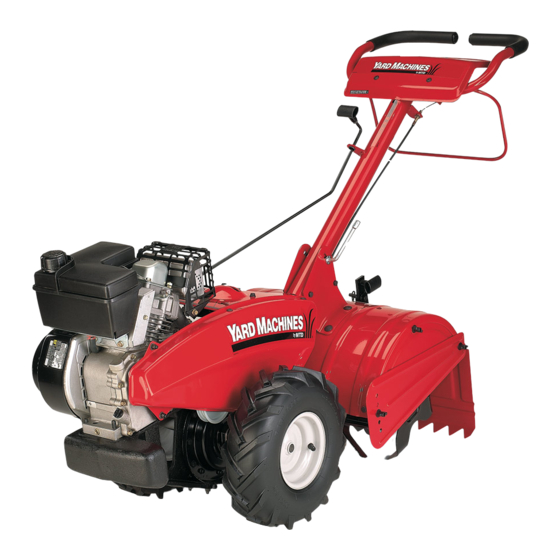
Operator's Manual
Rear Tine Tiller
Model Series 410
IMPORTANT:
READ SAFETY
RULES AND INSTRUCTIONS
CAREFULLY
Warning:
This unit is equipped with an internal combustion engine and should not be used on or near any unimproved
forest-
covered, brush-covered
or grass-covered
land unless the engine's exhaust system is equipped with a spark arrester meeting
applicable
local or state laws (if any), If a spark arrester is used, it should be maintained in effective working order by the operator,
In the State of California the above is required by law (Section 4442 of the California Public Resources Code), Other states may have
similar laws, Federal laws apply on federal lands, A spark arrester for the muffler is available through your nearest engine authorized
service dealer or contact the service department,
P,O, Box 361131 Cleveland, Ohio 44136-0019,
MTD LLC, P.O. BOX 361131 CLEVELAND,
OHIO 44136-0019
PRINTED IN U.S.A.
FORM
NO.
770-10136E
(10/05)
Advertisement
Table of Contents

Related Manuals for MTD 21AA413H700


Summary of Contents for MTD 21AA413H700
- Page 1 Federal laws apply on federal lands, A spark arrester for the muffler is available through your nearest engine authorized service dealer or contact the service department, P,O, Box 361131 Cleveland, Ohio 44136-0019, MTD LLC, P.O. BOX 361131 CLEVELAND, OHIO 44136-0019 PRINTED IN U.S.A.
-
Page 2: Customer Support
This Operator's Manual is an important part of your new tiller. It will help you assemble, prepare and maintain the unit for best performance. Please read and understand what it says. TABLEOFCONTENTS Content Page Content Page Important Safe Operation Practices Maintaining Your Tiller Assembling Your Tiller Troubleshooting... -
Page 3: Section 1: Important Safeoperation P Ractices
SECTION 1: IMPORTANT SAFEOPERATION P RACTICES WARNING: This symbol points out important safety instructions which, if not followed, could endanger the personal safety and/or property of yourself and others. Read and follow all instructions in this manual before attempting to operate this machine. Failure to comply with these instructions may result in personal injury. -
Page 4: Your Responsibility
Never o perate t hemachine a thigh transport Do not change the engine governor settings or speeds o nhard orslippery s urfaces. over-speed the engine. The governor controls the Exercise caution t oavoid slipping o rfalling. maximum safe operating speed of the engine. Look down andbehind andusecarewhen in Maintain or replace safety and instruction labels, as... -
Page 5: Section 2: Assembling Your Tiller
SECTION 2: ASSEMBLING YOUR TILLER NOTE: This operator's manual covers various models Insert hex bolt into the top hole of the depth stake of tillers. The units illustrated may vary slightly from assembly. Place flat washer on the hex bolt and your unit. - Page 6 Retainer Bracket Shoulder Bolt & Lock Nut Handle Gear ustment Rod (Model Series 420) Figure 3 Gear Shift Rod • Place the hex opening of the flange nut retainer bracket over the flange nut securing the handle adjustment crank and install the lock nut on the lower shoulder bolt.
-
Page 7: Tire Pressure
• Remove one hex nut from the threaded casing on NOTE: Keep hands out of belt area while unit is the end of the cable. Slip the wire up through the operating. slot on the cable bracket underneath the handle. •... -
Page 8: Section 3: Know Your Tiller
SECTION 3: KNOW YOUR TILLER Handle Handle Handle Adjustment_ Handle Stake Model 410 Series Figure 8 instructions warnings on the Reverse wheeldriveonly. WARNING: Read, understand, and follow Reverse machine this manual before Neutral operating. Transmission is in neutral. GearSelection Handle Wheels Forward Forward wheel drive only. -
Page 9: Choke Lever
ChokeLever FuelShut-Off V alve(_f (if Equipped) Equipped) The choke lever is located on top of the carburetor on Make sure the valve is in the On (horizontal) position the back of the engine underneath the muffler. It is used when starting the unit. Any time the tiller is not in to enrich the fuel mixture in the carburetor when starting operation (i.e., storing, performing maintenance or a cold engine. -
Page 10: Section 4: Operating Y Our Tiller
SECTION 4: OPERATING Y OUR TILLER • Stand at side of tiller. Grasp the starter handle and instructions warnings on the pull out slowly, until it pulls slightly harder. Let rope WARNING: Read, understand, and follow machine this manual before rewind slowly. - Page 11 • When using the tiller for the first time, use the To adjust the depth stake, remove the clevis pin and second adjustment hole from the top (1" of tilling hairpin clip. Move the depth stake to the desired setting depth).
-
Page 12: Section 5: Making Adjustments
SECTION 5: MAKING ADJUSTMENTS BeltTension Adjustment adjustments while the engine is running, WARNING: Never attempt to make any Periodic adjustment of the belt tension may be required except where specified operator's due to normal stretch and wear on the belt. Adjustment manual. -
Page 13: Section 6: Maintaining Your Tiller
SECTION 6: MAINTAINING YOUR TILLER Remove tine assemblies and lubricate the tine shafts at least once a season. and ground it against the engine before WARNING: Disconnect the spark plug wire performing any repairs or maintenance. Wheel Shafts Remove wheel assemblies and lubricate the axle shafts Engine at least once a season. -
Page 14: Off-Season Storage
NOTE: Off-Season S torage Upon reassembly, make certain the belt is routed over the idler pulley and inside of belt keepers by If the tiller will not be used for a period longer than 30 engine pulley. See Figure 10. days, the following steps should be taken to prepare the tiller for storage. -
Page 15: Section 7: Trouble Shooting Guide
SECTION 7: TROUBLE SHOOTING GUIDE Trouble Corrective Action Possible Cause(s) Engine fails to Fuel tank empty, or stale fuel. Fill tank with clean, fresh gasoline. Fuel will not last over thirty start days unless a fuel stabilizer is used. Throttle control lever not in correct starting Move throttle lever to start position. -
Page 16: Section 8: Parts Listformodel Series 410
SECTION 8: PARTS LISTFORMODEL SERIES 410... - Page 17 ModelSeries410 Ref. Ref. Part No. Part Description Part No. Part Description 710-1017 Hex Screw 1/4-20 x.625 686-0031A Belt Keeper Bracket Ass'y Shift Cover - Tecumseh Lock Washer 5/16 786-0168 736-0119 686-0095 710-0237 Crank Shift Assembly Hex Cap Screw 5/16-24 x.625 Hex Lock Nut 5/16-18 712-04063 756-0971...
- Page 18 ModelSeries410...
- Page 19 ModelSeries410 Ref. Ref. Part No. Part No. Part Description Part Description Shaft Seal 1.0 Dia Reinforcement Bracket 721-0378 786-0086 Hex Nut 7/16-20 Chain Case Gasket 712-0378 721-0295 Bell Washer.45 ID x 1.00D 736-0407 710-0258 Hex Cap Screw 1/4-20 x.625 Shaft Seal.75 Dia 721-0379 736-0329 Lock Washer 1/4...
- Page 20 ModelSeries410...
- Page 21 700-xxxx-0662. Black -- 0691 ; Black, Powder -- 0637; Blue, Midnight -- 0667; Charcoal -- 0483; Grey -- 0648; Grey, Oyster -- 0662; Orange -- 0606; Red -- 0650; Red, MTD -- 0638; Silver -- 0629; Yellow -- 0674.
- Page 22 NOTES...
- Page 23 NOTES...
- Page 24 MANUFACTURER'S LIMITED WARRANTY FOR: The limited warranty set forth below is given by MTD LLC with MTD does not extend any warranty for products sold or respect to new merchandise purchased and used in the exported outside of the United States, its possessions United States, its possessions and territories.