Table of Contents
Advertisement
Operator's Manual
10 in.
MiterMate
WITH LASER TRAC
Model No.
CAUTION:
Before using this Miter Saw,
read this manual and follow
all its Safety Rules and
Operating Instructions
Customer Help Line
For Technical Support
1-800-843-1682
Sears Brands Management Corporation Hoffman Estates, IL 60179 USA
See the full line of Craftsman
Click on the Craftsman Club
Part No. 137212260001
MITER SAW
™
®
137.212260
®
products at craftsman.com
®
link and join today!
●
Safety Instructions
●
Installation
●
Operation
●
Maintenance
●
Parts List
Sears Parts &
Repair Center
1-800-488-1222
1
Printed in China
Advertisement
Table of Contents

Related Manuals for Craftsman MiterMate 137.212260


Summary of Contents for Craftsman MiterMate 137.212260
- Page 1 For Technical Support Repair Center 1-800-843-1682 1-800-488-1222 Sears Brands Management Corporation Hoffman Estates, IL 60179 USA ® See the full line of Craftsman products at craftsman.com ® Click on the Craftsman Club link and join today! Part No. 137212260001 Printed in China...
-
Page 2: Table Of Contents
WARRANTY CRAFTSMAN FULL WARRANTY If this Craftsman product fails due to a manufacturer’s defect in material or workmanship with one year from the date of purchase, return it to any Sears store, Sears Parts & Repair Service Center, or other Craftsman outlet in the United States for free repair (or replacement if repair proves impossible). -
Page 3: Product Specifications
PRODUCT SPECIFICATIONS MOTOR Power Source ..............120V, 60Hz, 15A Speed ................4800RPM (No load) Brake ................. Electric Double Insulated ............... Yes BLADE SIZE Diameter................10 in. Arbor size................5/8 in. ROTATING TABLE: Diameter................12-3/4 in. Miter Detent Stops ............. 0°, 22.5°, 45° R & L Bevel Positive Stops ............ -
Page 4: Symbols
SYMBOLS WARNING ICONS Your power tool and its Operator’s Manual may contain “WARNING ICONS” (a picture symbol intended to alert you to, and/or instruct you how to avoid, a potentially hazardous condition). Understanding and heeding these symbols will help you operate your tool better and safer. Shown below are some of the symbols you may see. -
Page 5: Power Tool Safety
POWER TOOL SAFETY GENERAL SAFETY INSTRUCTIONS 8. DO NOT FORCE THE TOOL. It will BEFORE USING THIS POWER TOOL do the job better and safer at the rate for which it was designed. Safety is a combination of common sense, staying alert and knowing how 9. - Page 6 NOTE: Glasses or goggles not in and any other conditions that may compliance with ANSI Z87.1 could affect its operation. A guard or seriously injure you when they other part that is damaged should break. be properly repaired or replaced. 13.
-
Page 7: Compound Miter Saw Safety
COMPOUND MITER SAW SAFETY SPECIFIC SAFETY INSTRUCTIONS FOR THIS COMPOUND MITER SAW 10. BE SURE both the blade and the collar are clean and the arbor bolt 1. DO NOT USE THIN KERF is tightened securely. BLADES they can deflect and contact guard and can cause 11. - Page 8 21. NEVER cut metals or masonry 26. SHUT OFF the power before products with this tool. This miter servicing or adjusting the tool. saw is designed for use on wood 27. DISCONNECT the saw from and wood-like products. the power source and clean the 22.
-
Page 9: Electrical Requirements And Safety
ELECTRICAL REQUIREMENTS AND SAFETY way. If the plug does not fit fully in the WARNING outlet, reverse the plug. If it still does POWER SUPPLY AND MOTOR not fit, contact a qualified electrician to SPECIFICATIONS install the proper outlet. Do not change The AC motor used in this saw is the plug in any way. - Page 10 now be started and the cut finished. extension cords from sharp objects, 4. FUSES may “blow” or circuit excessive heat and damp or wet areas. breakers may trip frequently if: a. MOTOR is overloaded. Use a separate electrical circuit Overloading can occur if you for your tools.
-
Page 11: Accessories And Attachments
ACCESSORIES AND ATTACHMENTS RECOMMENDED ACCESSORIES WARNING WARNING ● To avoid the risk of personal injury, do not modify this power ● Use only accessories tool or use accessories not recommended for this miter recommended by Sears. saw. Follow instructions that ●... -
Page 12: Tools Needed For Assembly
TOOLS NEEDED FOR ASSEMBLY Not supplied Supplied Phillips Screwdriver Blade Wrench Adjustable Wrench Hex Wrench Slotted Screwdriver Combination Square Square Bar COMBINATION SQUARE MUST BE TRUE Should not gap or overlap when square is flipped over (see dotted figure). Straight edge or a 3/4 in. board, this Draw light line on edge must be perfectly straight. -
Page 13: Carton Contents
CARTON CONTENTS the illustration to make certain all UNPACKING YOUR MITER SAW items are accounted for, before WARNING discarding any packing material. To avoid injury from unexpected WARNING starting or electrical shock, do not ● If any part is missing or damaged, plug the power cord into a source do not attempt to assemble the of power during unpacking and... -
Page 14: Know Your Mitermate ™ Miter Saw
KNOW YOUR MITERMATE MITER SAW Switch Handle Angle Finder Storage Upper Blade Guard Motor Blade Dust Bag Sliding Fence Laser Guide Bevel Lock Handle Extension Wing Lock Knob Hold Plate Table Stop Plate Clamp ON/OFF Lower Blade Tigger Guard Switch Detent Detent Lock Knob for... -
Page 15: Glossary Of Terms
GLOSSARY OF TERMS EXTENSION CORD – An electric cord AMPERAGE (AMPS) – A measure used between power tools and outlets of the flow of electric current. Higher to extend the range of the tools. The ratings generally means the tool is more amerage your tool uses, the suited for heavier use. - Page 16 POSITIVE STOP LOCKING LEVER – HEEL – Misalignment of the blade. Locks the miter saw at a preset positive KERF – The width of a saw cut, stop for the desired miter angle. determined by the thickness and set of SWITCH HANDLE –...
-
Page 17: Assembly And Adjustments
ASSEMBLY AND ADJUSTMENTS 2. Push out the head lock down knob (2) WARNING into the locking hole (3). To avoid injury from unexpected IMPORTANT: To avoid damage, starting or electrical shock, do not never carry the miter saw by the switch plug the power cord into a source handle or the cutting arm. - Page 18 STORING THE ANGLE FINDER FIG. E (FIG. D) Mounting the Storage Clips The storage clips are used to store the angle finder. 1. Install the wider storage clip (1) by threading the bolt (2) into the hole provided upon the rear end of the switch handle (3).
- Page 19 6. Locate the arbor lock (5) on the 2. Place the blade collar (6) against motor, below the switch handle. (Fig. G) the blade and on the arbor. Thread 7. Press the arbor lock, holding it the arbor bolt (8) onto the arbor in a in firmly while turning the blade counterclockwise direction.
-
Page 20: Mounting Instructions
MOUNTING THE MITER SAW Fig. I (FIG. I, J, K) 1. Miter saw base WARNING 2. Hex head bolt 3. Rubber washer To avoid injury from unexpected 4. Flat washer saw movement: 5. Workbench ● Before moving the saw, disconnect 6. - Page 21 ADJUSTMENT INSTRUCTIONS Fig. L WARNING To avoid injury from an accidental start, make sure the switch is in the OFF position and the plug is not connected to the power source outlet. BEVEL STOP ADJUSTMENT Fig.M (FIG. L, M, N) NOTE: The upper blade guard has ...
- Page 22 45° Bevel Adjustment (Fig. O) To adjust the angle: 1. Unlock the bevel lock handle (1) 1. Unlock the left sliding fence unit by and tilt the cutting arm as far to the unlocking the positive stop lock lever left as possible. (1) behind the sliding fence unit and 2.
- Page 23 ADJUSTING SLIDING FENCE UNITS Fig. R SQUARENESS AND ALIGNMENT (FIG. Q, R, S) 1. Lower the cutting arm and lock in position. 2. Using a square, lay the heel of the square against the worktable, and the rule against the blade. Check to see if the angle between the worktable and the blade is 90°.
- Page 24 ADJUSTING LOCK LEVERS (FIG. T) 5. Repeat until adjusted properly, and After a period of use, the lock levers tighten the locknut to secure the might loosen and couldn’t clamp the adjustment bolt into position. sliding fence units tightly. Fig. U An adjustment is needed.
-
Page 25: Operation
OPERATION SAFETY INSTRUCTIONS FOR BASIC SAW OPERATION ● Tighten the arbor bolt. ● Tighten the cover plate screw. BEFORE USING THE MITER SAW ● Check for damaged parts. WARNING Check for: ● Alignment of moving parts To avoid mistakes that could cause ●... - Page 26 Operators Manual for recommended or attachment to do a job it was not accessories. Follow the instructions designed to do. Use a different tool that come with the accessory. The for any workpiece that can’t be held use of improper accessories may in a solidly braced, fixed position.
- Page 27 clamp and get a solid grasp on. would cause your hand or fingers to Plan the way you will grasp the be within 6 inches of the saw blade workpiece from start to finish. Avoid the workpiece is too small. Keep awkward operations and hand hands and fingers out of the “no positions.
- Page 28 BODY AND HAND POSITION (FIG. W) Fig. W WARNING Never place hands near the cutting area. Proper positioning of your body and hands when operating the miter saw will make cutting easier and safer. Keep children away. Keep all visitors at a safe distance from the miter saw.
- Page 29 NOTE: (Fig. Z) ● All the adjustments for the ● Laser Aperture Label: operation of the laser guide has AVOID EXPOSURE: Laser been completed at the factory. radiation is emitted from this ● Laser beam is calibrated and set aperture. (Fig. Z) up to project to the left of the blade.
- Page 30 TURNING SAW ON (FIG. AA) 2. If the left sliding fence unit (1) is To reduce the likelihood of accidental chosen, unlock the left sliding fence starting, a thumb activated lock-OFF unit by unlocking the positive stop switch is located on top of the switch lock lever (2) behind the left sliding handle.
- Page 31 IMPORANT: COMPOUND CUT (FIG. DD) Make sure that both sides of the sliding fences are A compound cut is the combination of a positioned so that they do not miter and a bevel cut simultaneously. contact the saw blade. Check this 1.
-
Page 32: Setting Up The Tables For Angle Cuts Using The Angle Finder
Fig. DD SETTING UP THE TABLES FOR ANGLE CUTS USING THE ANGLE FINDER (FIG. FF, GG) The MiterMate™ accurate angle cutting is suited to do with the fact that most walls and ceiling are not 90 degrees to each other, and so you can make the accurate angles for fewer miscut and quicker task completion. -
Page 33: Cutting Crown Molding
Cutting crown molding: 2. Tighten the knob to the lock position and remove the MiterMate™ angle Your miter saw is suited for making the finder from the corner. difficult task of cutting crown molding easily. To fit properly, crown molding Adjusting the sliding fences for must be cut with extreme accuracy. -
Page 34: Cutting Base Molding
4. Use the clamp to secure the molding Wall/Ground (Base Molding Orientation) piece and hold it at the proper spring Inside corner Outside corner angle. Right Left Right Left Orientation NOTE: Use the extension wings to side of side of side of side of steady long molding pieces. - Page 35 CONVENTIONAL WAY OF CUTTING Cutting crown molding CROWN/BASE MOLDING (Fig. NN, OO): Your compound miter saw is suited The following instructions are not the for the difficult task of cutting crown optimum way to cut molding using the molding. To fit properly, crown molding MiterMate™...
- Page 36 Bevel/Miter Settings Fig. OO Settings for standard crown molding lying flat on compound miter saw table Inside Corner Outside Corner NOTE: The chart below references a compound cut for crown molding ONLY WHEN THE ANGLE BETWEEN THE WALLS EQUALS EXACTLY 90°. BEVEL MITER SETTING TYPE OF CUT...
-
Page 37: Crown Moulding Chart
CROWN MOULDING CHART MiterMate ™ Miter Saw Miter and Bevel Angle Settings Wall to Crown Molding Angle 52/38 Crown Moulding 45/45 Crown Moulding 52/38 Crown Moulding 45/45 Crown Moulding Angle Between Angle Between Mitre Setting Bevel Setting Mitre Setting Bevel Setting Mitre Setting Bevel Setting Mitre Setting... -
Page 38: Maintenance
MAINTENANCE MAINTENANCE a break-in period that reduces motor performance and increases wear. DANGER To avoid injury, never put lubricants Fig. PP on the blade while it is spinning. WARNING ● To avoid fire or toxic reaction, never use gasoline, naphtha acetone, lacquer thinner or similar highly volatile solvents to clean the miter saw. - Page 39 LUBRICATION (FIG. QQ) Fig. QQ All the motor bearings in this tool are Central pivot of lubricated with a sufficient amount of plastic guard high grade lubricant for the life of the unit under normal operating conditions; therefore, no further lubrication is required.
-
Page 40: Troubleshooting Guide
TROUBLESHOOTING GUIDE WARNING To avoid injury from accidental starting, always turn switch OFF and unplug the tool before moving, replacing the blade or making adjustments. TROUBLESHOOTING GUIDE - MOTOR PROBLEM PROBLEM CAUSE SUGGESTED CORRECTIVE ACTION Brake does 1. Motor brushes not sealed or 1. -
Page 41: Parts List
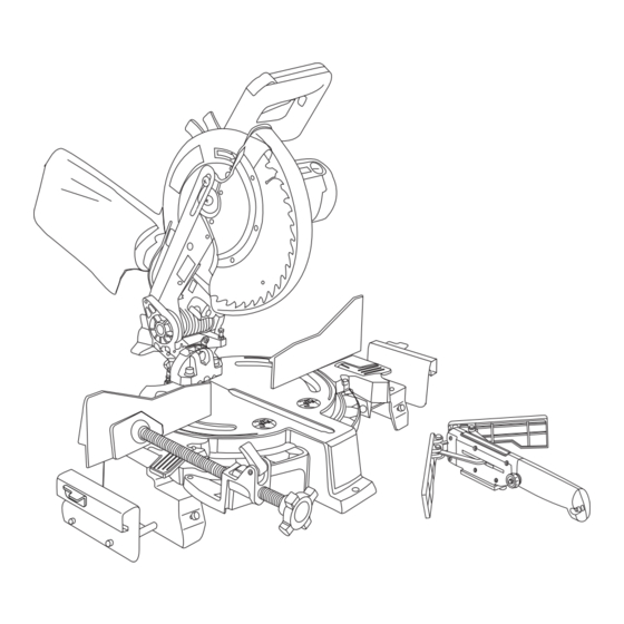
MODEL NO. 137.212260 WARNING When servicing use only CRAFTSMAN replacement parts. Use of any other parts may create a HAZARD or cause product damage. Any attempt to repair or replace electrical parts on this Miter Saw may create a HAZARD unless repair is done by a qualified service technician. - Page 42 10” MiterMate™ MITER SAW MODEL NO. 137.212260 SCHEMATIC A...
- Page 43 10” MiterMate™ MITER SAW MODEL NO. 137.212260 PARTS LIST FOR SAW SCHEMATIC B DESCRIPTION SIZE QTY ID DESCRIPTION SIZE 081U SUPPORT 2VED RIGHT-ASSIST-FENCE 0824 PIVOT SHAFT 2VEE LEFT-ASSIST-FENCE 0826 NEEDLE POINTER 2VEF RUGHT-CLAMP-HANDLE 0828 ROTATION SLIDE PLATE 2VEH LEFT-CLAMP-HANDLE 0D7W CLEVIS PIN...
- Page 44 10” MiterMate™ MITER SAW MODEL NO. 137.212260 SCHEMATIC B...
- Page 45 10” MiterMate™ MITER SAW MODEL NO. 137.212260 PARTS LIST FOR MOTOR I.D. Description Size 0HX9 NEEDLE BEARING 0JCD SPRING PIN 0JX2 HEX.-SOC SET SCREW M5*0.8-6 0K43 CR.RE. PAN HD. SCREW & WASHER M5*0.8-16 0K44 CR.RE. PAN HD. SCREW & WASHER M5*0.8-12...
- Page 46 10” MiterMate™ MITER SAW MODEL NO. 137.212260 MOTOR SCHEMATIC...
-
Page 47: Repair Protection Agreements
REPAIR PROTECTION AGREEMENTS Congratulations on making a smart purchase. Your new Craftsman product ® is designed and manufactured for years of dependable operation. But like all products, it may require repair from time to time. That’s when having a Repair Protection Agreement can save you money and aggravation. - Page 48 Get it fixed, at your home or ours! Your Home For troubleshooting, product manuals and expert advice: www.managemylife.com For repair – in your home – of all major brand appliances, lawn and garden equipment, or heating and cooling systems, no matter who made it, no matter who sold it! For the replacement parts, accessories and owner’s manuals that you need to do-it-yourself.