
Related Manuals for Toshiba RAS-10YKH-E


Summary of Contents for Toshiba RAS-10YKH-E
- Page 1 FILE NO. DAS-SM-00-003 SERVICE MANUAL AIR-CONDITIONER SPLIT WALL TYPE RAS-10YKH-E / RAS-10YAH-E RAS-13YKH-E / RAS-13YAH-E RAS-10YKH-ES / RAS-10YAH-ES RAS-13YKH-ES / RAS-13YAH-ES...
-
Page 2: Table Of Contents
CONTENTS 1. SPECIFICATIONS ..................3 2. CONSTRUCTION VIEWS ................ 6 3. WIRING DIAGRAM .................. 9 4. SPECIFICATIONS OF ELECTRICAL PARTS ........11 5. REFRIGERANT CYCLE DIAGRAM ............. 13 6. CONTROL BLOCK DIAGRAM ............. 17 7. OPERATION DESCRIPTIONS ..............18 8. INSTALLATION PROCEDURE .............. 27 9. -
Page 3: Specifications
1. SPECIFICATIONS RAS-10YKH-E / RAS-10YAH-E, RAS-13YKH-E / RAS-13YAH-E MODEL RAS-10YKH-E/10YAH-E RAS-13YKH-E/13YAH-E ITEM Cooling Heating Cooling Heating 220V–240V 220V–240V 220V–240V 220V–240V Capacity 2,65–2,70 3,00–3,10 3,45–3,50 4,00–4,10 Phase Single Power source 220–240 Power consumption 0,98–1,02 0,89–0,91 1,26–1,30 1,19–1,27 Power factor 95–90 95–88 98–92... - Page 4 RAS-10YKH-ES / RAS-10YAH-ES, RAS-13YKH-ES / RAS-13YAH-ES RAS-10YKH-ES/10YAH-ES RAS-13YKH-ES/13YAH-ES MODEL ITEM Cooling Heating Cooling Heating 220V–240V Capacity 2,65–2,70 3,00–3,10 3,45–3,50 4,00–4,10 Phase Single Power source 220–240 Power consumption 0,98–1,02 0,89–0,91 1,26–1,30 1,19–1,27 Power factor 95–90 95–88 98–94 97–93 220V–240V Running current Indoor/Outdoor 0,11/4,44 - 0,11/4,46 0,11/4,15 - 0,11/4,10 0,15/5,70 - 0,15/5,61 0,15/5,43 - 0,15/5,54 Starting current...
- Page 5 6 °C Notes : CHARGELESS RAS-10YKH-E, RAS-10YKH-ES • No additional refrigerant required. • This air conditioner accepts a connection piping length of up to 10m and a head of up to 5m. • There is no need to add the refrigerant as long as the total length of the connection piping is up to 10m.
-
Page 6: Construction Views
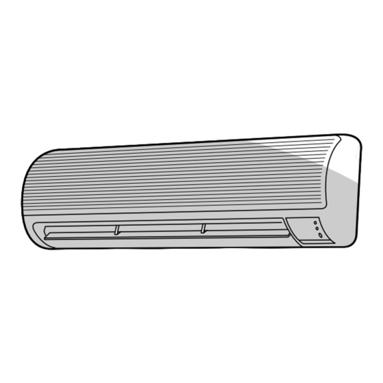
2. CONSTRUCTION VIEWS 2-1. Indoor Unit Heat exchanger Air inlet Air filter Air outlet Knock out system Front panel Back body Hanger Drain hose (0,54m) Hanger Knock out system Connecting pipe (0,39m) Connecting pipe (0,49m) (Flare Ø9,52) (Flare Ø6,35) (Flare Ø12,7 for 13YKH-E only) 65,5 65,5 Hanger... -
Page 7: Outdoor Unit
Liquid side (flare Ø6,35) Ø6 Hole Ø11x14 Hole 8-Ø6 Holes (For fixing the outdoor unit) Handle 4-Ø11x14 Long holes (For anchor bolt Ø8-Ø10) Fan guard Ø420 TOSHIBA Electric parts cover Service port View Inlet port 600 or more Inlet port 100 or more... - Page 8 RAS-13YAH-E, RAS-13YAH-ES Detail Drawing Gas side (Flare Ø12,7 for 13YAH-E, Flare Ø9,52 for 13YAH-ES) Liquid side (Flare Ø6,35) Ø6 hole Ø11x14 hole 8-Ø6 hole(for fixing outdoor unit) Ø25 Drain outlet 6-Ø11x14 hole (for Ø8-Ø10 anchor bolt) Handle Fan guard Electric parts cover Ø420 Service port...
-
Page 9: Wiring Diagram
3. WIRING DIAGRAM RAS-10YKH-E / RAS-10YAH-E LOUVER MOTOR RAS-10YKH-ES / RAS-10YAH-ES INFRARED RAYS RECEIVE AND INDICATION PARTS CN25 THERMAL FUSE 77˚C x 2 CN04 CN07 CN13 SG01 GRN&YEL VARISTOR VARISTOR DB01 6,3A 250V POWER TERMINAL POWER BLOCK SUPPLY CIRCUIT 1Ø 220V-240V... - Page 10 RAS-13YKH-E / RAS-13YAH-E RAS-13YKH-ES / RAS-13YAH-ES LOUVER MOTOR INFRARED RAYS RECEIVE AND INDICATION PARTS CN25 THERMAL FUSE 77˚C x 2 CN04 CN07 CN13 SG01 GRN&YEL VARISTOR DB01 6,3A 250V POWER TERMINAL POWER BLOCK SUPPLY CIRCUIT Ø 220V-240V DC 12V RY02 RY01 DC 5V 50Hz...
-
Page 11: Specifications Of Electrical Parts
4. SPECIFICATIONS OF ELECTRICAL PARTS 4-1. Indoor Unit RAS-10YKH-E, RAS-10YKH-ES RAS-13YKH-E, RAS-13YKH-ES PARTS NAME TYPE SPECIFICATIONS Output (Rated) 20W, 6poles, 1phase, 220–240V, 50Hz Fan motor (for indoor) MMF-240-20-4A Red-Black White-Black Winding resistance (W) (at 20°C) 220,8 324,3 10k W at 25°C Thermo. - Page 12 4-2. Outdoor Unit RAS-10YAH-E, RAS-10YAH-ES RAS-13YAH-E, RAS-13YAH-ES PARTS NAME MODELS TYPE SPECIFICATIONS Output (Rated) 750W, 2poles, 1phase, 220–240V, 50Hz RAS-10YAH-E PH120T1-4C Winding resistance ( W ) (at 20°C) 4,53 8,73 Output (Rated) 1100W, 2poles, 1phase, 220–240V, 50Hz RAS-13YAH-E PH170T2-4L2 Winding resistance (W) (at 20°C) 2,22 3,04...
-
Page 13: Refrigerant Cycle Diagram
5. REFRIGERANT CYCLE DIAGRAM RAS-10YKH-E / RAS-10YAH-E Indoor unit Evaporator Cooling 0,39m 0,49m Heating (Connecting pipe) (Connecting pipe) ø9,52 ø6,35 Cross flow fan O.D.:9,52mm O.D.:6,35mm Packed valve Packed valve (ø9,52) (ø6,35) Heating Cooling 4-way valve Heating Cooling Compressor PH120T Capillary tube ø1,5x500... - Page 14 RAS-13YKH-E / RAS-13YAH-E Indoor unit Heat exchanger Cooling 0,49m 0,39m Heating (Connecting pipe) (Connecting pipe) ø12,7 ø6,35 Cross flow fan O.D.:12,7mm O.D.:6,35mm Packed valve Packed valve (ø12,7) (ø6,35) Gas container connection (Reinstall etc.) Heating Cooling 4-way valve Capillary tube ø0,6x1500 Heating Cooling Compressor PH170T2-4L2 Capillary tube...
- Page 15 RAS-10YKH-ES / RAS-10YAH-ES Indoor unit Evaporator Cooling 0,39m 0,49m Heating (Connecting pipe) (Connecting pipe) ø9,52 ø6,35 Cross flow fan O.D.:9,52mm O.D.:6,35mm Packed valve Packed valve (ø9,52) (ø6,35) Heating Cooling 4-way valve Muffler Muffler Heating Cooling Compressor PA118X1T-4FZ Capillary tube ø0,8x400 Dryer Capillary tube Accumulator...
- Page 16 RAS-13YKH-ES / RAS-13YAH-ES (Note) Indoor unit Maximum pipe length is 15m Maximum pipe head is 6m Heat exchanger Cooling 0,49m 0,39m (Connecting pipe) (Connecting pipe) ø9,52 ø6,35 Cross flow fan O.D.:9,52mm O.D.:6,35mm Packed valve Packed valve (ø9,52) (ø6,35) Gas container connection (Reinstall etc.) Heating Cooling 4-way valve...
- Page 17 Main Unit Control Panel C. P. U Operation Functions Heat Exchanger Sensor Display Thermo. Sensor • Louver Control Timer Display Current Sensor • 3-minutes Delay at Restart for Compressor (Compressor Current) ECONO. Sign Display Infrared Rays Signal Receiver Infrared Initializing Circuit •...
-
Page 18: Operation Descriptions
2) When the FAN is set to LOW, MED, or HIGH, the indoor fan motor operates with a constant in volume as listed in Table 7-1-1. HIGH Air volume (m /hr) Indication of RAS-10YKH-E RAS13-YKH-E FAN SPEED RAS-10YKH-ES RAS13-YKH-ES AUTO Manual... -
Page 19: Heat Operation
7-2-1. Louver Control 7-4. HEAT Operation (1) By pushing the SET button of the remote control (MODE of the remote control : HEAT) during the operation, the louver can be set to the (1) Relays compressor 4-way valve, outdoor fan and desired position. -
Page 20: Auto Operation
Fig. 7-5-1. tected by the indoor heat-exchanger sensor is 20°C or below, the indoor fan stops and if the temperature rises to 25°C (RAS-10YKH-E, RAS- 10YKH-ES), 35°C (RAS-13YKH-E, RAS-13YKH- ES) or above, the fan is restarted. The details are in 7-10. - Page 21 (C.T). (1) In the ECONO. mode, the set temp. by the remote control is changed automatically as shown in Fig. 7-6-1. RAS-10YKH-E, RAS-13YKH-E (2) Fan speed → LOW RAS-10YKH-ES, RAS-13YKH-ES Compressor Outdoor fan (˚C)
-
Page 22: Heating Operation
Control is performed as shown in Fig. 7-8-1. Control is performed as shown in Fig. 7-10-1 and 7-10-2. Heat exchanger temperature RAS-10YKH-E, RAS-10YKH-ES Compressor, (˚C) Outdoor fan Heat exchanger temperature (˚C) -
Page 23: Defrost Operation
7-11. Defrost Operation 7-11-2. Defrost Operation Time Control <In case of B> During the heating operation, the outdoor heat (1) The heating operation is performed for at least 40 exchanger temperature goes down and sometimes it minutes. is frozen. (2) The maximum defrost operation time is 6 min- In this case, the air conditioner stops the heating utes. - Page 24 7-12. Auto Restart Function 7-12-1. How to Set the Auto Restart To set the Auto Restart function, proceed as follows: This unit is equipped with an Automatic restarting Access the TEMPORARY button located in the lower facility which allows the unit to restart and resume right hand corner beneath the hinged front panel of the set operating conditions in the event of a power the indoor unit (please refer to section on PARTS...
- Page 25 7-12-2. How to Cancel the Auto Restart The system will now be required to manually restart with the remote control after the main supply is To cancel the Auto Restart function, proceed as turned off. follows: Cancellation is carried out: Repeat the setting procedure: the unit will acknowl- edge the instruction and bleep three times.
-
Page 26: Installation Procedure
8. INSTALLATION PROCEDURE 8-1. Safety Cautions For general public use Power supply cord of parts of appliance for Outdoor use shall be more than polychloroprene sheathed flexible cord (design H05 RN-F), or cord designation 245 IEC 57. CAUTION TO DISCONNECT THE APPLIANCE FROM THE MAINS SUPPLY. This appliance must be connected to the mains by means of a circuit breaker or a switch with a contact separation of at least 3 mm. - Page 27 And make sure the equipment to be earthed. • Appliance shall be installed in accordance with national wiring requlations. If you detect any damage, do not install the unit. Contact your Toshiba dealer immediately. CAUTION • Exposure of unit to water or other moisture before installation will result in an electrical short.
-
Page 28: Installation Diagram Of Indoor And Outdoor Units
8-2. Installation Diagram of Indoor and Outdoor Units For installation of the indoor unit, use the paper pattern on the back. For the rear left and left piping Clip anchor Wall Hook Hook Front cabinet 1 Installation Insert the cushion between plate Front panel the indoor unit and wall,... - Page 29 8-3. Installation • Secure the outdoor unit with the anchor bolts if the unit is likely to be exposed to a strong wind. 8-3-1. Optional Parts • Use ø8 or ø10 anchor bolts. • If it is necessary to drain the defrost water from the Part Parts name Q’ty...
- Page 30 8-3-2. Installation Parts Parts with an asterisk ( ) are packaged with the outdoor unit. Name of parts Name of parts Name of parts Part Part Part Q'ty Q'ty Q'ty Installation plate x 1 Mounting screw ø4x 25 x 6 Drain nipple Deodorizing filter x 1 Remote control holder x 1...
-
Page 31: Indoor Unit
8-4. Indoor Unit 8-4-1. Cutting a Hole and Mounting Installation Plate K Installation place <Cutting a hole> • A place which provides the spaces around the When installing the refrigerant pipes from the rear. indoor unit as shown in the diagram in section 8-2. •... - Page 32 An approved power supply cord and plug must be used. NOTE : 4 Mounting screw Ø4 x 25 • Perform wiring works so as to allow a generous wiring capacity. Fig. 8-4-4 RAS-10YKH-E RAS-13YKH-E MODEL RAS-10YKH-ES RAS-13YKH-ES Power source 50Hz 220–240V...
- Page 33 8-4-3. Wiring Connection Taking out the power cord WARNING To plug the cable in the plug receptacle, take the following precaution. Slitted portion THIS APPLIANCE MUST BE EARTHED. IMPORTANT • Cut off the slitted portion in the side face of the rear panel to take out the power cord.
- Page 34 <How to connect the connecting cable> <How to install the front cabinet on the indoor unit> Wiring of the connecting cable can be carried out Install the front cabinet through the opposite order of without removing of the front panel. “How to remove the front cabinet”.
- Page 35 <Left-hand connection with piping> 8-4-5. Indoor Unit Installation Bend the connecting pipe so that it is laid within 43 (1) Pass the pipe through the hole in the wall, and mm above the wall surface. If the connecting pipe is hook the indoor unit on the installation plate at laid exceeding 43 mm above the wall surface, the the upper hooks.
- Page 36 Fig. 8-4-17 • An allowable length of the connecting pipe is up to : RAS-10YKH-E, RAS-10YKH-ES : 10 m (2) Put water in the drain pan and make sure that the RAS-13YKH-E, RAS-13YKH-ES : 15 m water is drained outdoors.
- Page 37 8-5-2. Refrigerant Piping Connection CAUTION <Flaring> (1) Cut the pipe with a pipe cutter. Installation in the following places may result in trouble. Do not install the unit in such places. • A place full of machine oil. • A saline place such as coast. Obliquity Roughness Warp...
- Page 38 8-5-3. Vacuum Pumping Manifold valve High pressure Pressure gage side handle INFORMATION Low pressure side handle In order to prevent any other refrigerant from being Charge hose (A) charged accidentally, each port of the manifold has Outdoor unit been changed in shape. Charge Indoor unit hose (B)
- Page 39 8-5-4. Wiring Connection 8-6. Others (1) Remove the electric parts cover from the outdoor 8-6-1. Gas Leak Test unit. Flare nut connections (indoor unit) (2) Connect the connecting cable to the terminals as identified with their respective matched numbers on the terminal block of indoor and outdoor units. (Strip the sheath of connecting cable with follow- ing stripping length to and insert into the terminal block.)
-
Page 40: Troubleshooting Chart
9. TROUBLESHOOTING CHART TROUBLESHOOTING PROCEDURES : • Following details of “What to be pre-checked first”, make sure of the basic items. • When there is no trouble corresponding to above, check in detail the faulty parts following “How to judge faulty parts by symptoms”... -
Page 41: Primary Judgement Of Trouble Sources
9-2. Primary Judgement of Trouble Sources 9-2-1. Role of Indoor Unit Controller The indoor unit controller receives the operation commands from the remote control and assumes the following functions. • Measurement of the draft air temperature of the indoor heat exchanger by using the thermo sensor (TA). •... - Page 42 (2) Self-diagnosis with remote control With the indoor unit control, self-diagnosis of protective circuit action can be done by turning the remote control operation into service mode, operating the remote control, observing the remote control indicators and checking whether TIMER lamp blinks (5 Hz). [ METHOD ] Push the [CHK] button with a thin tip of pencil or others.
- Page 43 Table 9-2-3 Block level Diagnosis function Judgment and action Check Check Conditioner Block Symptom Condition code code status 1.Check thermo. sensor. Indoor Thermo. sensor Continued Indicated when P .C. board short/break. operation detected abnormal 2.If it is OK, check P .C. board. Heat exchanger Continued Indicated when...
-
Page 44: Troubleshooting Flowcharts
9-3. Troubleshooting Flowcharts 9-3-1. Power can not be Turned on (No Operation at All) <Preliminary checks> Operation (1) Is the supply voltage normal? Check Items (2) Is the connection to the AC output OK.? Main cause Shut off the power supply from AC outlet once and Countermeasure turn it on after 5 seconds. - Page 45 9-3-2. Power can not be Turned on after Replacing Indoor P.C. Board <Checking Procedure> Connect the AC Power supply Return the wiring of the Does the OPERATION Is it wired as shown power relay is returned to in Figure below? lamp blink? the normal procedure.
- Page 46 9-3-3. Outdoor Unit does not Operate Shut off the power supply from AC outlet once and turn it on after 5 seconds. Does the OPERATION lamp blink? See “Power can not be turned on”. Does the power turn on by See “Power can not be turned on”.
- Page 47 9-3-4. Only Compressor does not Operate Shut off the power supply from AC outlet once and turn it on after 5 seconds. Does the OPERATION lamp blink? See “Power can not be turned on”. Does the power turn on by See “Power can not be turned on”.
- Page 48 9-3-5. Only Outdoor Fan does not Operate Shut off the power supply from AC outlet once and turn it on after 5 seconds. Does the OPERATION lamp blink? See “Power can not be turned on”. Does the power turn on by See “Power can not be turned on”.
- Page 49 9-3-6. Only 4-Way Valve does not Operate (During Heating Operation) Shut off the power supply from AC outlet once and turn it on after 5 seconds. Does the OPERATION lamp blink? See "Power can not be turned on". Does the power turn on by See "Power can not be turned on".
- Page 50 9-3-7. Only the Indoor Fan does not Operate < Check procedure > Shut off the power supply once. Turn the power supply. Does the fan stop in Replace the P.C. board. Control P.C. board is defective. no operating status? Start the operation with low fan setting in cool operation.
- Page 51 9-4. How to Check the Remote Control (Including the Indoor P.C. Board) There is no beep from the indoor unit. Push the START/STOP button. The operation lamp of the air conditioner main unit does not light. Does the transmission indicator blink? Short-circuit the metal terminal at the side of the battery compartment...
- Page 52 9-4-1. How to Check the P.C. Board (2) Inspection procedures 1) When a P .C. board is judged to be defective, (1) Operating precautions check for disconnection, burning, or discolora- 1) When removing the front panel or the P .C. tion of the copper foil pattern or this P .C.
- Page 53 (3) Checking procedure Table 9-4-1 Procedure Check Point (Symptom) Causes Shut off the power supply and 1. Is the fuse blown? 1. • Application of shock voltage. remove the P .C. board assembly from • Overload by short-circuit of the parts. the electronic parts base.
- Page 54 9-4-2. P.C. Board Layout Top View Bottom View – 54 –...
- Page 55 Table 9-4-2 Approximate value of the sensor (thermistor) resistance (TA, TC) (= kΩ) Temperature 0°C 10°C 20°C 25°C 30°C Sensor Themo. Sensor 35,8 20,7 12,6 10,0 7,92 9-4-3. How to Reduce the Operation Time of TEMP. the Anti-Restart Timer (1) Set the operation mode, temperature, and air START/STOP flow rate to be applied with the timer short mode.
-
Page 56: Part Replacement
10. PART REPLACEMENT 10-1. Indoor Unit RAS-10YKH-E, RAS-10YKH-ES, RAS-13YKH-E, RAS-13YKH-ES Part name Procedure Remarks Front panel 1) After stopping the operation of the air conditioner, be sure to turn off the circuit breaker or disconnect the power plug from the AC wall socket. - Page 57 Part name Procedure Remarks Horizontal grille 1) Perform the process Note: 2) Remove the screw fixing the louver motor, and The horizontal remove the louver motor. Louver motor grille can not be 3) Remove the shaft of the horizontal grille from the removed without drain-pan.
- Page 58 10-2. Microcomputer RAS-10YKH-E, RAS-10YKH-ES, RAS-13YKH-E, RAS-13YKH-ES Part name Procedure Remarks Common 1) Turn the power supply off to stop the operation of air- Replace the thermal fuse, terminal procedure conditioner, and disconnect the power cord from the AC block, power cord, microcomputer ass’y supply.
- Page 59 10-3. Outdoor Unit RAS-10YAH-E, RAS-10YAH-ES Part name Procedure Remarks Common 1) Stop the operation of air-conditioner, and disconnect procedure the power cord from the AC supply. 2) Remove Electric parts cover. Remove (1- ST1T Ø4 x 10 l) 7-ST1T ´ 3) Remove the cord clamp (2- ST2T Ø4 x 12 l) and remove the connecting cable.
- Page 60 RAS-13YAH-E, RAS-13YAH-ES Part name Procedure Remarks Common 1) Stop the operation of air-conditioner, and disconnect procedure the power cord from the AC supply. Remove 2) Remove E-parts cover. (2- ST1T Ø4 x 10 l) 7-ST1T ´ 3) Remove the cord clamp (2- ST2T Ø4 x 12 l) and remove the connecting cable.
-
Page 61: Exploded Views And Parts List
11. EXPLODED VIEWS AND PARTS LIST 11-1. Indoor Unit (1) Location Part Location Part Description Description 43T60001 Base, Terminal 43T69051 P .C. Board Assembly, 2P , AC 300V, 20A MCC-772 (13YKH-E, 13YKH-ES) 43T60002 Base, Terminal 43T69052 P .C. Board Assembly, 3P , AC 300V, 20A MCC-772 (10YKH-E, 10YKH-ES) 43T69004 Sensor, Heat Exchanger... - Page 62 11-1. Indoor Unit (2) RAS-10YKH-E, RAS-10YKH-ES, RAS-13YKH-E, RAS-13YKH-ES Location Part Location Part Description Description 43T00307 Panel Assembly, Front (10YKH-E) 43T47016 Pipe, Suction 43T00309 Panel Assembly, Front (10YKH-ES) (13YKH-E) 43T00306 Panel Assembly, Front (13YKH-E) 43T49007 Pipe, Shield 43T00308 Panel Assembly, Front (13YKH-ES)
- Page 63 11-2. Outdoor Unit RAS-10YAH-E 17, 26 12, 15 8, 9 14 2 10, 11 7 : CAPILLARY TUBE 27 : DRYER Location Part Location Part Description Description 43T19001 Guard, Fan 43T49030 Solenoid coil 43T20001 Fan, Propeller 43T19005 Handle 43005037 Cabinet, Front 43T49001 Rubber, Cushion 43T43001 Condenser (10YAH-E) 43T79001 Nipple, Drain...
- Page 64 RAS-10YAH-ES 13, 16, 25, 26 9, 11 15 2 10, 12 7 : CAPILLARY TUBE 8 : CAPILLARY TUBE Location Part Location Part Description Description 43T19001 Guard, Fan 43T21001 Motor, Fan, UE6-21SJ5P 43T20001 Fan, Propeller 43T47001 Nut, Flange 43005037 Cabinet, Front 43T46013 Coil, 4-Way, VHV-01AI501A 43T43011 Condenser 43T19005 Handle...
- Page 65 RAS-13YAH-E 21, 36 17,18 31, 32 15,16 Location Part Location Part Description Description 43005144 Cabinet, Front 43T47007 Tube, Capillary, 1,2DIA 43005143 Cabinet-Side 43T47014 Tube, Capillary, 1,7DIA 43042446 Base 43041764 Compressor, PH1702T2-4L2 43T19007 Guard, Fan 43T97001 Nut, Flat-Washer 43T19005 Handle 43T49008 Cushion, Rubber 43T19002 Stopper, Guard 43045085 Dryer 43T62007 Cover, E-Parts...
- Page 66 RAS-13YAH-ES Location Part Location Part Description Description 43005144 Cabinet, Front 43T47021 Bonnet 43005143 Cabinet-Side 43T46011 Valve, Packed 9,52 43042446 Base 43T47020 Bonnet 43T19007 Guard, Fan 43T47007 Tube, Capillary, 1,2DIA 43T19005 Handle 43T47008 Tube, Capillary, 1,5DIA 43T19002 Stopper, Guard 43041700 Compressor, PA160x2T-4FZ 43T62007 Cover, E-Parts 43T97001 Nut, Flat-Washer 43020302 Fan, Propeller...
- Page 67 TOSHIBA CARRIER (THAILAND) CO., LTD. 144/9 MOO 5, BANGKADI INDUSTRIAL PARK, TIVANON ROAD, TAMBOL BANGKADI, AMPHUR MUANG, PATHUMTHANI 12000, THAILAND.