Invacare Meteor Service Manual
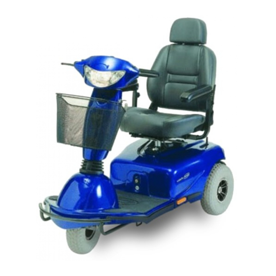
3-wheeled version/4-wheeled version
Hide thumbs
Also See for Meteor:
- User manual (60 pages) ,
- User manual (67 pages) ,
- User manual (57 pages)

Related Manuals for Invacare Meteor


Summary of Contents for Invacare Meteor
- Page 1 SERVICE MANUAL ® Invacare Meteor This manual contains instructions about troubleshooting repair Edition: 02.05.2002...
-
Page 2: Table Of Contents
Before operation / after completion of service work:............10 Tool list ..........................10 ® The Invacare Meteor in overview ..............11 Layout of modules, components and displays and controls ..........11 Module composition / variations, accessories..............11 3.2.1 Module composition / variations ..................11 3.2.2... - Page 3 Invacare Meteor ® Service Manual 7.1.5 Seat belt........................... 19 7.1.6 Seat..........................19 7.1.7 Release lever ........................20 7.1.8 Seat rails .......................... 20 7.1.9 Top seat tube ........................21 7.1.10 Seat plate ........................21 Handlebar, operating console ....................23 7.2.1 General ..........................23 7.2.2...
- Page 4 Invacare Meteor ® Service Manual 7.7.3 Steering linkage ....................... 45 7.7.4 Stub axle .......................... 47 7.7.5 Transverse control arm....................47 7.7.6 Fork steering tube ......................48 Batteries ..........................49 7.8.1 Checking the battery (batteries) battery cable and fuses ..........49 7.8.2...
-
Page 5: General Information
Safe handling of electrical measurement instruments (multimeter). Transport back to the manufacturer If the Meteor has to be shipped back to the manufacturer for major repairs, you should always use the original packaging for transport. You should also include as accurate a fault description as possible. -
Page 6: Invacare Service
Invacare Meteor ® Service Manual ® Invacare service ® If you have problems or questions please contact Invacare service: ® ® Invacare Deutschland GmbH Invacare Dehmer Str. 66 Sdr. Ringvej 39 D-32549 Bad Oeynhausen 2605 Brøndby Deutschland Danmark ( (Kundendienst):... - Page 7 +46 - (0) 491 – 101 80 invacare.O-hamn@swipnet.se • Alterations to the Meteor which occur as a result of incorrectly or improperly executed maintenance ® or overhaul work lead to the exclusion of all liability on the side of Invacare...
-
Page 8: Safety And Assembly Instructions
Observe the minimum requirements for carrying out the work (see chapter entitled " General information). The Invacare® Meteor must be switched off before removal of voltage-carrying components. First remove the negative and then the positive terminal clamp from the battery, and then remove the bat-... -
Page 9: During Dismantling/Reassembly
When reassembling ensure that these locking devices are correctly engaged. Batteries: If the Invacare® Meteor needs to be laid on its side for the purpose of carrying out service work, the batteries must be removed first. -
Page 10: Before Operation / After Completion Of Service Work
Invacare Meteor ® Service Manual Before operation / after completion of service work: Caution: Check all fixings for tight fit. Check all parts for correct interlocking. Only op- erate the wheelchair with correct tyre pressure (2.0 bar). Always carry out a functional test of any components replaced in addition to a trial run after completing any service work. -
Page 11: The Invacare Meteor In Overview
® The Invacare Meteor in overview Layout of modules, components and displays and controls The following figures show the layout of Meteor modules. Removal and reassembly of spare parts is described in Chapter .7 ü NOTE: The arrangement of displays and controls for the three or four-wheel Meteor is the same. -
Page 12: Inspection Plan
Invacare Meteor ® Service Manual Inspection plan ü Component Check Remedy Chapter: • Þ Adjust, replace Wheel suspen- see oper- Check drive wheels for sion and wheels ating tight fit and side play manual • Þ Adjust, replace wheel, axle,... -
Page 13: Operational Faults
§ display the blink code, stop the Meteor and hold it at a standstill until the electronic system has been switched off and switched on again §... -
Page 14: Fault Causes
Invacare Meteor ® Service Manual Fault causes Fault description Fault cause Fault remedy Wheelchair will not start disengaging lever set to "Rear", push disengaging lever forwards motor disengaged operating unit status display has gone out • batteries defective replace batteries •... -
Page 15: Electronics Error Codes
Battery voltage too Stops driving Battery voltage has sunk below 16.5 V. Recharge battery If you switch the Meteor off for a few minutes, the battery can often recharge itself to such a level that a short run is still possible. - Page 16 Switch of the meteor, wait a few minutes and then switch it on again. The electronic system has determined a motor short-circuit.
-
Page 17: Repair And Replacement
Invacare Meteor ® Service Manual Repair and replacement Seat unit CAUTION: seat adjustments such as seat depth, seat height, backrest angle and distance between armrests or the steering column should be individu- ally adjusted to suit the user. The settings should be called up once again when service work is completed 7.1.1... -
Page 18: Armrests
Invacare Meteor ® Service Manual 7.1.2 Armrests Disassembly Loosen the handwheel under the armrest. Pull the armrest out upwards. Reassembly Reassembly takes place in reverse order to disassembly. 7.1.3 Armrest receptacles Disassembly Loosen handwheel beneath seat. Withdraw armrest receptacle to the side. -
Page 19: Seat Belt
Invacare Meteor ® Service Manual 7.1.5 Seat belt Caution: Only replace the seat belt complete, in other words both the left-hand and right-hand part together. Disassembly Loosen the Allen screw each side for the left-hand and right-hand seatbelt, and remove together with the seatbelt and one washer each. -
Page 20: Release Lever
Invacare Meteor ® Service Manual engage by turning slightly. Let release lever go 7.1.7 Release lever Caution: Risk of crushing when working on slide rails, adjustment levers and springs! Disassembly Dismantle seat (see section 7.1.2). Turn the seat round with the backrest folded down. -
Page 21: Top Seat Tube
Invacare Meteor ® Service Manual Reassembly Reassembly takes place in reverse order to disassembly. 7.1.9 Top seat tube Disassembly Dismantle seat (see section 7.1.2). Unscrew the hex bolts and nuts from the seat at- tachment and remove together with washers. - Page 22 Invacare Meteor ® Service Manual Reassembly Reassembly takes place in reverse order to disassembly.
-
Page 23: Handlebar, Operating Console
Invacare Meteor ® Service Manual Handlebar, operating console CAUTION: Make sure you have blocked the vehicle up securely before working Caution: Risk of accidents! Always carry out a functional test and a trial run after service work on the drive lever or electronics! 7.2.1... - Page 24 Invacare Meteor ® Service Manual...
-
Page 25: Operating Console And Keypad
Invacare Meteor ® Service Manual 7.2.2 Operating console and keypad Disassembly Remove plastic caps. Loosen Allen screws and washers and remove. Carefully lift up operating console. Remove the caps from the turret, and dismantle the turret. Unscrew the operating circuit board. -
Page 26: Steering Column Panelling
Invacare Meteor ® Service Manual 7.2.3 Steering column panelling Disassembly Loosen the screw connections between front and rear steering column panelling. Remove the Phillips screws. Dismantle the rear steering column panelling. Loosen the screw connections between front steer- ing column panelling and the basket holder. -
Page 27: Drive Regulator
Invacare Meteor ® Service Manual Loosen the Phillips screw at the end of the Bowden cable out of the clamping sleeve and pull the Bow- den cable out of the attachment. Draw the clamping sleeve off the Bowden cable. Remove the Bowden cable Reassembly Reassembly takes place in reverse order to disassembly. -
Page 28: Potentiometer
Invacare Meteor ® Service Manual 7.2.6 Potentiometer Disassembly Dismantle the operating console (see section 7.2.1). Loosen the potentiometer fixing. Remove the Phillips screws. Loosen the Allen screws located on the side of the potentiometer. Pull the potentiometer out downwards. Strip the potentiometer cable of its insulation and de-solder. -
Page 29: Headlights
Invacare Meteor ® Service Manual Remove the headlight when it has been angled from bottom to top. Turn bold holder out together with bulb. Replace bulb. Reassembly Reassembly takes place in reverse order to disassembly. 7.2.8 Headlights Disassembly Dismantle the bulbs (see section 7.2.7). -
Page 30: Steering Column
Invacare Meteor ® Service Manual Reassembly Reassembly takes place in the reverse order. 7.2.10 Steering column Disassembly Disassembly of the steering column takes place as shown in the adjacent exploded drawing. Reassembly Reassembly takes place in the reverse order. -
Page 31: Panelling
Invacare Meteor ® Service Manual Panelling 7.3.1 Front panelling (three-wheeled version) General The front panelling individual parts (3-wheeled version) are shown in the following drawing. Disassembly Dismantle the steering column (see section 7.2.10. Dismantle the rear panelling (see section 7.3.3). -
Page 32: Front Panelling (Four-Wheeled Version)
Invacare Meteor ® Service Manual 7.3.2 Front panelling (four-wheeled version) General The front panelling individual parts (4-wheeled version) are shown in the following drawing. Disassembly Dismantle the steering column (see section 7.2.10. Dismantle the rear panelling (see section 7.3.3). Remove foot mat. -
Page 33: Rear Panelling (Three And Four-Wheeled Version)
Invacare Meteor ® Service Manual 7.3.3 Rear panelling (three and four-wheeled version) The rear panelling individual parts are shown in the following drawing. Disassembly Dismantle seat (see section 7.1.2). Loosen side Velcro fastenings. Loosen cable connections. Remove rear panelling. Reassembly Reassembly (3 and 4-wheeled versions) takes place in reverse order to disassembly. -
Page 34: Wheels
Invacare Meteor ® Service Manual Wheels ü NOTE: Disassembly of wheels and repair of tyres is described in the operating manual. Disk brake 7.5.1 Brake Bowden cable Disassembly Dismantle the operating console (see section 7.2.2). Dismantle the rear steering column panelling (see section 7.2.3). -
Page 35: Brake Calliper
Invacare Meteor ® Service Manual 7.5.2 Brake calliper Caution: Before starting work, lay the vehicle down on its side on a relatively firm underlay, or block up the frame so that the steering wheels are not loaded. Disassembly Dismantle the brake Bowden cable (see section 7.5.1). - Page 36 Invacare Meteor ® Service Manual Fit the drive wheel (see section 7.4). Fit the brake calliper (see section 7.5.1).
-
Page 37: Front Wheel Suspension, Three-Wheeled Version
Invacare Meteor ® Service Manual Front wheel suspension, three-wheeled version Caution: Before starting work, lay the vehicle down on its side on a relatively firm underlay so that the front wheel is not loaded and is easily acces- sible from both sides, or block up the vehicle securely. - Page 38 Invacare Meteor ® Service Manual...
-
Page 39: Front Wheel Axle
Pull the axle out of the wheel. Reassembly ü NOTE: The left-hand side of the wheel is labelled with the word Invacare ® on the top wheel flange. Push the axle through the wheel. Fit the washer and sleeve over the axle (right-hand wheel side). -
Page 40: Shock Absorber, Front
Invacare Meteor ® Service Manual 7.6.3 Shock absorber, front Disassembly Dismantle the front panelling (see section 7.3.1). Loosen the spring holder (turn collar) and slacken coil spring. Loosen nuts from top and bottom suspension. Pull the shock absorbers (with coil springs) and washers from top and bottom suspension. -
Page 41: Wheel Fork
Invacare Meteor ® Service Manual 7.6.4 Wheel fork Disassembly Dismantle the steering column (see section 7.2.10. Dismantle the front panelling (see section 7.3.1). Dismantle the front wheel (see section 7.4). Dismantle the shock absorber (see section 7.6.3). Unscrew the top union nut. -
Page 42: Front Wheel Suspension, Four-Wheeled Version
Invacare Meteor ® Service Manual Front wheel suspension, four-wheeled version Caution: Before starting work, lay the vehicle down on its side on a relatively firm underlay so that the front wheel is not loaded and is easily acces- sible from both sides, or block up the vehicle securely. - Page 43 Invacare Meteor ® Service Manual...
-
Page 44: Shock Absorber, Front
Invacare Meteor ® Service Manual 7.7.2 Shock absorber, front Disassembly Dismantle the front panelling (see section 7.3.2). Loosen the spring holder (turn collar) and slacken coil spring. Remove the bottom Allen screw, the Allen screw with internal threads, two collars and the sleeve. -
Page 45: Steering Linkage
Invacare Meteor ® Service Manual 7.7.3 Steering linkage Disassembly of the steering linkage Dismantle the front panelling (see section 7.3.2). Remove the nut, washer and the stop. Remove the Allen screw. Remove the TO linkage (to fork steering tube), washer and FROM linkage (to right-hand wheel). - Page 46 Invacare Meteor ® Service Manual Reassembly of steering linkage ü NOTE: When reassembling the steering linkage, you must adjust it so that the steering is located centrally and the tracking is parallel. The stop must be adjusted when reassembling. Fit the FROM linkage (to fork steering tube), washer and TO linkage (to right-hand wheel) with the Allen screw in the left-hand stub axle.
-
Page 47: Stub Axle
Invacare Meteor ® Service Manual 7.7.4 Stub axle Disassembly Dismantle the front panelling (see section 7.3.2). Remove the front wheel (see section 7.4). Dismantle the steering linkage (see section 7.7.3. Remove the nut from the bolted connection. Remove the nut, collar and the hex bolt. -
Page 48: Fork Steering Tube
Invacare Meteor ® Service Manual Reassembly of the transverse control arm Reassembly takes place in reverse order to disas- sembly. 7.7.6 Fork steering tube Disassembly of the transverse control arm Dismantle the steering column (see section 7.2.10. Dismantle the steering linkage (see section 7.7.3). -
Page 49: Batteries
Invacare Meteor ® Service Manual Batteries Caution: Observe the safety information (see chapt. 2)! Do not bridge battery terminals, risk of short circuit! Take care when removing batteries, risk of crushing! Take off all rings or metal jewellery worn on hands and wrists. -
Page 50: Electronics Box
Invacare Meteor ® Service Manual Electronics box Caution: Remove battery fuses. Caution: Before starting work, lay the vehicle down on its side on a relatively firm underlay so that the chassis floor beneath the electronics box is easily accessible, or block up the vehicle securely. -
Page 51: Drive
Invacare Meteor ® Service Manual 7.10 Drive CAUTION: Make sure you have blocked the vehicle up securely before working. The ground clearance must be at least 150 mm in order to be able to remove the drive. Please note the high drive unit weight, risk of crush- ing! Always carry out a functional test and trial run after service work on the drive. -
Page 52: Reassembly
Invacare Meteor ® Service Manual 7.10.2 Reassembly Place the drive unit on the chassis. Place the axle mounting bracket on the drive unit. Screw the axle mounting bracket to the chassis using the Allen screws, washers and nuts. Plug the drive cable plugs back in in the positions you noted previously.