Advertisement
NOTE:
Please read all instructions
carefully before using this
product
Table of Contents
Safety Notice
Hardware Identifier
Assembly Instruction
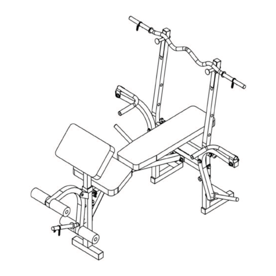
Exploded Diagram
Parts List
Warranty
Ordering Parts
Model
WM-343
Retain This
Manual for
Reference
May 29, 2001
OWNER'S
MANUAL
COMPETITOR
WM-343 BENCH
14777 Don Julian Rd., City of Industry, CA 91746
Tel: (800) 999-8899 Fax (626) 961-9966
www.impex-fitness.com
info@impex-fitness.com
IMPEX INC.
Advertisement

Related Manuals for Impex COMPETITOR WM-343


Summary of Contents for Impex COMPETITOR WM-343
- Page 1 Exploded Diagram Parts List Warranty Ordering Parts Model WM-343 Retain This Manual for Reference May 29, 2001 OWNER'S MANUAL COMPETITOR WM-343 BENCH IMPEX INC. 14777 Don Julian Rd., City of Industry, CA 91746 Tel: (800) 999-8899 Fax (626) 961-9966 www.impex-fitness.com info@impex-fitness.com...
-
Page 2: Table Of Contents
PARTS LIST...…..9 WARRANTY...….10 ORDERING PARTS...…10 BEFORE YOU BEGIN Thank you for selecting the COMPETITOR WM -343 BENCH by IMPEX FITNESS PRODUCTS. For your safety and benefit, read this manual carefully before using the machine. As a manufacturer, we are committed to provide you complete customer satisfaction. If you have... -
Page 3: Important Safety Notice
PHYSICIAN. THIS IS ESPECIALLY IMPORTANT FOR INDIVIDUALS OVER THE AGE OF 35 OR PERSONS WITH PRE-EXISTING HEALTH PROBLEMS. READ ALL INSTRUCTIONS BEFORE USING ANY FITNESS EQUIPMENT. IMPEX INC. ASSUMES NO RESPONSIBILITY FOR PERSONAL INJURY OR PROPERTY DAMAGE SUSTAINED BY OR THROUGH THE USE OF THIS PRODUCT. -
Page 5: Assembly Instructions
ASSEMBLY INSTRUCTION Tools required to assembly the machine: Two Adjustable Wrenches STEP 1 (SEE Diagram 1) A.) Connect the two Rear Upright Beams (#1) by a Cross Brace (#25) in the Mid-span. Fasten them by two M10x 2 3/8” Bolts (#14), four Bracket (#12), and two M10 Aircraft Nuts (#15) on each side of the Cross Brace. - Page 6 STEP 2 (SEE DIAGRAM 2) A.) Connect the Front Stabilizer (#49) to the Main Seat Support (#32) and secure them with two M10 x 1” Bolts (#42), four Nuts (#15). DO NOT tighten the nuts and bolts yet. B.) Connect the Main Seat Support (#32) to the Cross Brace (#25) and secure it with two M10 x 2 3/8”...
- Page 7 STEP 3 (SEE DIAGRAM 3) A.) Attach a 7/8” Washer (#13) onto a M10 x 4 ½” Bolt (#24). Insert the Bolt through the Butterfly (#22). Place a M10 Regular Nut onto the Bolt. Then insert the Bolt through the hole on the Rear Upright Beam (#1).
- Page 8 STEP 4 (SEE DIAGRAM 4) A.) Attach the hole-side of the Backrest Supports (#28) onto both ends of the Pivot on the Main Seat Support (#32). The other side rest against the Backrest Adjustment Bar (#10). B.) Place the Backrest Board (#33) onto the Backrest Support (#28). Fasten it with four M6 x 1 3/8”...
-
Page 10: Parts List
PARTS LIST KEY NO. DESCRIPTION Rear Upright Beam Right Bar Catch Curl Bar Spring Clip 1” Curl Bar Flat End Cap Left Bar Catch Bar Catch Panel 7/8” Flat End Cap 1 ½” Square End Cap Backrest Adjustment Bar Knob Bracket 7/8”... -
Page 11: Warranty
No other warranty beyond that specifically set forth above is authorized by IMPEX. IMPEX is not responsible or liable for indirect, special or consequential damages arising out of or in connection with the use or performance of the product or other damages with respect to any economic loss, loss of property, loss of revenues or profits, loss of enjoyments or use, costs of removal, installation or other consequential damages or whatsoever natures.