Table of Contents
Advertisement
NOTE:
Please read all instructions
carefully before using this
product
Table of Contents
Safety Notice
Hardware Identifier
Assembly Instruction
Exploded Diagram
Parts List
Warranty
Ordering Parts
Model
WM-205
Retain This
Manual for
Reference
07-03-08
OWNER'S
MANUAL
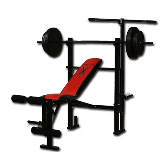
COMPETITOR
WM-205 COMBO BENCH
14777 Don Julian Rd., City of Industry, CA 91746
Tel: (800) 999-8899 Fax (626) 961-9966
www.impex-fitness.com
info@impex-fitness.com
®
IMPEX
INC.
Advertisement
Table of Contents

Related Manuals for Impex Competitor WM-205


Summary of Contents for Impex Competitor WM-205
- Page 1 Exploded Diagram Parts List Warranty Ordering Parts Model WM-205 Retain This Manual for Reference 07-03-08 OWNER'S MANUAL COMPETITOR WM-205 COMBO BENCH IMPEX 14777 Don Julian Rd., City of Industry, CA 91746 Tel: (800) 999-8899 Fax (626) 961-9966 www.impex-fitness.com info@impex-fitness.com ® INC.
-
Page 2: Table Of Contents
PARTS LIST...…. WARRANTY...…. ORDERING PARTS...…. BEFORE YOU BEGIN Thank you for selecting the Competitor WM-205 COMBO BENCH by ® IMPEX INC. For your safety and benefit, read this manual carefully before using the machine. As a manufacturer, we are committed to provide you complete customer satisfaction. -
Page 3: Important Safety Notice
PHYSICIAN. THIS IS ESPECIALLY IMPORTANT FOR INDIVIDUALS OVER THE AGE OF 35 OR PERSONS WITH PRE-EXISTING HEALTH PROBLEMS. READ ALL INSTRUCTIONS BEFORE USING ANY FITNESS EQUIPMENT. IMPEX INC. ASSUMES NO RESPONSIBILITY FOR PERSONAL INJURY OR PROPERTY DAMAGE SUSTAINED BY OR THROUGH THE USE OF THIS PRODUCT. - Page 4 WARNING LABEL REPLACEMENT The Warning Label shown here has been placed on the Cross Brace. If the label is missing or illegible, please call customer service at 1-800-999-8899 for replacement. Apply the label in location shown.
-
Page 5: Hardware Pack
HARDWARE PACK NOTE: The following parts are not drawn to scale. Please use your own ruler or scale to measure the size. -
Page 6: Assembly Instructions
ASSEMBLY INSTRUCTION Tools required assembling the machine: Two Adjustable Wrenches. NOTE: It is strongly recommended two or more people assembling this equipment to avoid possible injury. STEP 1 (See Diagram 1) A.) Connect the Left & Right Upright Beams (#1 & #19) by a Cross Brace (#2) in the mid-span. - Page 7 STEP 2 (See Diagram 2) A.) Connect the Front Stabilizer (#5) to the Main Seat Support (#3) and secure them with three M8 x 5/8” Hex Bolts (#41) and Ø 5/8” Washers (#45). DO NOT tighten the nuts and bolts yet. B.) Connect the Main Seat Support to the Cross Brace (#2).
- Page 8 STEP 3 (See Diagram 3) A.) Attach the Leg Developer (#9) to the open bracket on the Front Stabilizer (#5). Secure it with one M10 x 2 ¾” Hex Bolt (#38), Ø ¾” Washer (#44), and M10 Aircraft Nut (#47). Do not over tighten the Nut and Bolt.
- Page 9 STEP 4 (See Diagram 4) A.) Attach the Backrest Supports (#14) onto both ends of the Pivot on the Main Seat Support (#3). Place the other end rest against the Backrest Adjustment Bar (#8). B.) Place the Backrest Board (#17) onto the Backrest Supports. Secure it with four M6 x 1 ½” Hex Bolts (#43) and ½”...
- Page 10 STEP 5 (See Diagram 5) A.) Attach the ball end of the Cable (#33) to the Pulley (#30). Place the Pulley in the open slot on the Upper Lat Bar Frame (#52). Secure it with one M10 x 2” Hex Bolt (#40), two Pulley Bushings (#29), and one M10 Aircraft Nut (#47).
-
Page 12: Parts List
PARTS LIST KEY NO. DESCRIPTION Left Upright Beam Cross Brace Main Seat Support Diagonal Support Front Stabilizer Right Bar Catch Left Bar Catch Backrest Adjustment Bar Leg Developer Foam Tube Weight Holder Lower Lat Bar Frame Lat Bar Backrest Support M6 x 1 ¼”... -
Page 13: Warranty
IMPEX authorized service center or for products used for commercial or rental purposes. No other warranty beyond that specifically set forth above is authorized by IMPEX.