Table of Contents
Advertisement
www.proform.com
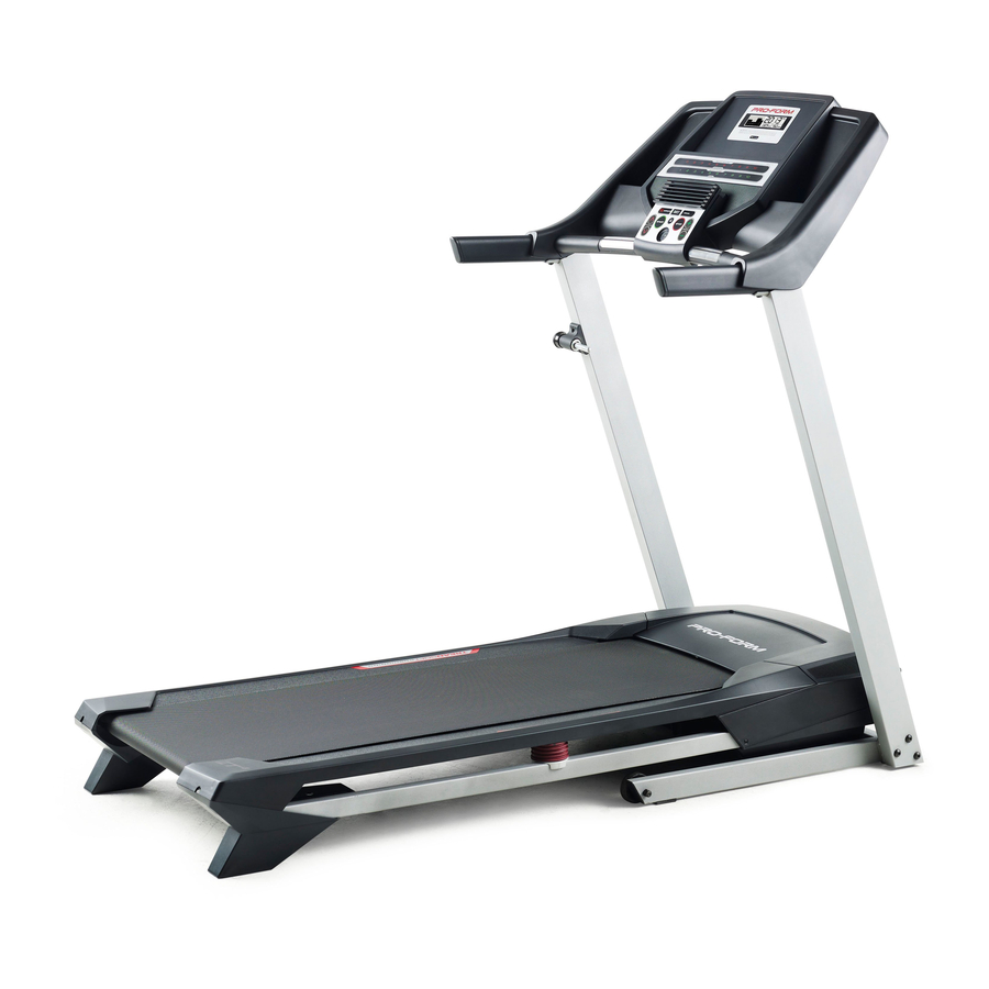
Model No. PFTL49013.0
USER’'S MANUAL
Serial No.
Write the serial number in the space
above for reference.
Serial Number
Decal
ACTIVATE YOUR
WARRANTY
To register your product and
activate your warranty today,
go to www.proformservice.com/
registration.
CUSTOMER CARE
For service at any time, go to
www.proformservice.com.
Or call 1-888-533-1333
Mon.––Fri. 6 a.m.––6 p.m. MT
Sat. 8 a.m.––4 p.m. MT
Please do not contact the store.
CAUTION
Read all precautions and instruc-
tions in this manual before using
this equipment. Keep this manual
for future reference.
Advertisement
Table of Contents

Related Manuals for Pro-Form ZT4


Summary of Contents for Pro-Form ZT4
- Page 1 www.proform.com Model No. PFTL49013.0 USER’’S MANUAL Serial No. Write the serial number in the space above for reference. Serial Number Decal ACTIVATE YOUR WARRANTY To register your product and activate your warranty today, go to www.proformservice.com/ registration. CUSTOMER CARE For service at any time, go to www.proformservice.com.
-
Page 2: Table Of Contents
TABLE OF CONTENTS WARNING DECAL PLACEMENT ............. . . 2 IMPORTANT PRECAUTIONS . -
Page 3: Important Precautions
IMPORTANT PRECAUTIONS WARNING: To reduce the risk of burns, fire, electric shock, or injury to persons, read all important precautions and instructions in this manual and all warnings on your treadmill before using your treadmill. ICON assumes no responsibility for personal injury or property damage sus- tained by or through the use of this product. - Page 4 20. The heart rate monitor is not a medical 24. Do not change the incline of the treadmill by device. Various factors, including the user’’s placing objects under the treadmill. movement, may affect the accuracy of heart rate readings. The heart rate monitor is 25.
- Page 5 STANDARD SERVICE PLANS...
-
Page 6: Before You Begin
Thank you for selecting the new PROFORM ® manual. To help us assist you, note the product model treadmill. The ZT4 treadmill provides an impressive number and serial number before contacting us. The selection of features designed to make your workouts model number and the location of the serial number at home more effective and enjoyable. -
Page 7: Part Identification Chart
PART IDENTIFICATION CHART Use the drawings below to identify small parts used for assembly. The number in parentheses below each draw- ing is the key number of the part, from the PART LIST near the end of this manual. The number following the key number is the quantity used for assembly. -
Page 8: Assembly
ASSEMBLY •• To hire an authorized service technician to •• Left parts are marked ““L”” or ““Left”” and right parts assemble the treadmill, call 1-800-445-2480. are marked ““R”” or ““Right.”” •• Assembly requires two persons. •• To identify small parts, see page 7. ••... - Page 9 3. Identify the Right Upright (76). Have a second person hold the Right Upright near the Base (74). Wire See the inset drawing. Tie the wire tie in the Right Upright (76) securely around the end of the Upright Wire (63). Then, insert the Upright Wire into the lower end of the Right Upright as you pull the other end of the wire tie out of the top of the Right Upright.
- Page 10 5. Hold the Right Upright (76) against the Base (74). Be careful not to pinch the Upright Wire (63). Insert a 3/8" x 3 1/4" Screw (2) with a 3/8" Star Washer (3) into the top hole in the Right Upright (76).
- Page 11 7. Set the console assembly face down on a soft surface to avoid scratching the console Console assembly. Assembly Remove the two screws (C) from the Console Crossbar (61). Then, remove the Console Crossbar. Discard the screws. 8. Remove the four indicated screws (D) from the Left and Right Handrails (59, 64).
- Page 12 9. Attach the Console Crossbar (61) to the Left and Right Uprights (66, 76) with four #10 x 3/4" Screws (8) and four #10 Star Washers (23). Start all four Screws, and then tighten them. Firmly tighten the two 5/16" x 3/4" Screws (5) and the two 5/16"...
- Page 13 11. Insert the wires into the Right Handrail (64) through the indicated hole as you set the con- Console Assembly sole assembly on the Uprights (66, 76). Make sure that no wires are pinched. Attach the console assembly with ten #8 x 3/4" Screws (4).
-
Page 14: Operation And Adjustment
OPERATION AND ADJUSTMENT HOW TO CONNECT THE POWER CORD nominal 120-volt circuit capable of carrying 15 or more amps. To avoid overloading the circuit, do Use a Surge Suppressor not plug other electrical devices, except for low- power devices such as cell phone chargers, into Your treadmill, like other electronic equipment, can be the surge suppressor or into an outlet on the same damaged by sudden voltage changes in your home’’s... - Page 15 CONSOLE DIAGRAM FEATURES OF THE CONSOLE To turn on the power, see page 16. To use the man- ual mode, see page 16. To use a preset workout, see The treadmill console offers a selection of features page 18. To use the information mode, see page 19. designed to make your workouts more effective and To use the sound system, see page 19.
-
Page 16: To Turn On Power
HOW TO TURN ON THE POWER HOW TO USE THE MANUAL MODE IMPORTANT: If the treadmill has been exposed to 1. Insert the key into the console. cold temperatures, allow it to warm to room tem- perature before you turn on the power. If you do See HOW TO TURN ON THE POWER at the left. - Page 17 4. Change the incline of the treadmill as desired. display shows the information that you are most interested in viewing. Note: While information is To change the incline of the treadmill, press the shown in the upper display, the same information Incline increase and decrease buttons or one of will not be shown in the lower left or lower right the numbered Quick Incline buttons.
-
Page 18: To Use A Preset Workout
HOW TO USE A PRESET WORKOUT ash. If a different speed and/or incline setting is programmed for the next segment, the speed and/ 1. Insert the key into the console. or incline setting will ash in the display to alert you. The treadmill will then automatically adjust to the See HOW TO TURN ON THE POWER on page 16. -
Page 19: Information Mode
THE INFORMATION MODE power switch into the reset position, and insert the key into the console. However, when you remove the The console features an information mode that keeps key, the displays will remain lit, although the buttons track of treadmill usage information and allows you to will not function. -
Page 20: How To Fold And Move The Treadmill
HOW TO FOLD AND MOVE THE TREADMILL HOW TO FOLD THE TREADMILL HOW TO MOVE THE TREADMILL Before folding the treadmill, adjust the incline to Before moving the treadmill, fold it as described at the zero. If you do not do this, you may damage the left. -
Page 21: Troubleshooting
TROUBLESHOOTING Most treadmill problems can be solved by following c. Remove the key from the console, and then the simple steps below. Find the symptom that reinsert it. applies, and follow the steps listed. If further assis- tance is needed, see the front cover of this manual. d. - Page 22 SYMPTOM: The walking belt slows when walked on SYMPTOM: The walking belt is off-center or slips when walked on a. Use only a surge suppressor that meets all of the speci cations described on page 14. a. If the walking belt is off-center, rst remove the key and UNPLUG THE POWER CORD.
-
Page 23: Exercise Guidelines
EXERCISE GUIDELINES Burning Fat——To burn fat effectively, you must exer- WARNING: cise at a low intensity level for a sustained period of Before beginning this time. During the first few minutes of exercise, your or any exercise program, consult your physi- body uses carbohydrate calories for energy. -
Page 24: Part List
PART LIST Model No. PFTL49013.0 R0813A Key No. Qty. Description Key No. Qty. Description #8 x 1/2" Ground Screw Right Foot Rail 3/8" x 3 1/4" Screw Idler Roller 3/8" Star Washer Left Rear Foot #8 x 3/4" Screw Wire Tie 5/16"... -
Page 25: Exploded Drawing
EXPLODED DRAWING A Model No. PFTL49013.0 R0813A... - Page 26 EXPLODED DRAWING B Model No. PFTL49013.0 R0813A...
- Page 27 EXPLODED DRAWING C Model No. PFTL49013.0 R0813A...
-
Page 28: Ordering Replacement Parts
ORDERING REPLACEMENT PARTS To order replacement parts, please see the front cover of this manual. To help us assist you, be prepared to provide the following information when contacting us: •• the model number and serial number of the product (see the front cover of this manual) ••...