GE Profile PGCS1RKZ Technical Service Manual
Profile bottom mount ice and water refrigerators
Hide thumbs
Also See for Profile PGCS1RKZ:
- Dimensions and installation information (2 pages) ,
- Energy manual (1 page)
Table of Contents
Advertisement
GE Appliances
Technical Service Guide
August 2011
Profi le Bottom
Mount Ice and Water
Refrigerators
PGCS1RKZ
PFCF1RKZ
PFSS5RKZ
PGSS5RKZ
31-9215
9215
GE Appliances
General Electric Company
Louisville, Kentucky 40225
xxxxx
xxxx xx xxxxx
xxxxx
xxxxxx
xxxxxx
xxxxx
xxxxx
xxxx xx xxxxx
xxxxx
xxxx xx xxxxx
xxxxx
xxxxxx
xxxxxx
xxxxx
xxxxx
xxxx xx xxxxx
Advertisement
Table of Contents
Troubleshooting

Related Manuals for GE Profile PGCS1RKZ


Summary of Contents for GE Profile PGCS1RKZ
- Page 1 GE Appliances Technical Service Guide August 2011 Profi le Bottom Mount Ice and Water Refrigerators PGCS1RKZ PFCF1RKZ PFSS5RKZ PGSS5RKZ xxxxx xxxx xx xxxxx xxxxx xxxxxx xxxxxx xxxxx xxxx xx xxxxx xxxxx xxxxxx xxxxxx xxxxx xxxxx xxxx xx xxxxx xxxxx xxxxx...
- Page 2 If grounding wires, screws, straps, clips, nuts, or washers used to complete a path to ground are removed for service, they must be returned to their original position and properly fastened. GE Appliances Technical Service Guide Copyright © 2011 All rights reserved. This service guide may not be reproduced in whole or in part in any form without written permission from the General Electric Company.
-
Page 3: Table Of Contents
Table of Contents Airfl ow ....................................20 Anti-Tip Floor Bracket (on 21-ft. models) ......................7 Articulating Door Mullion ............................52 Auger Motor ..................................35 Bottom Freezer Drawer ...............................27 Components ..................................22 Components Locator Views ............................17 Condenser Fan ................................56 Control Board Connector Locator ..........................15 Control Diagnostics Using Temperature Display ....................60 Control Features ................................ -
Page 4: Introduction
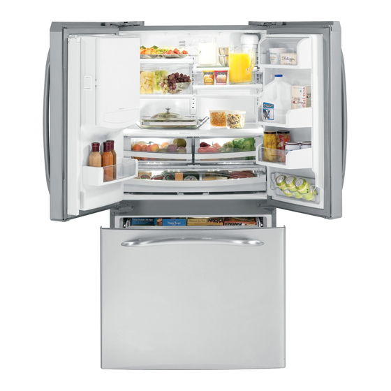
Introduction This new Profi le Bottom Mount Ice and Water Refrigerator has the following features:* • Available in 21- and 25-cubic foot capacity, single freezer or double drawer freezer model with fresh food french door confi guration. • ENERGY STAR® qualifi ed. •... -
Page 5: Technical Data
Technical Data FRESH FOOD 1/3” FRESH FOOD COLD AIR MIXED AIR TO CABINET BROWN EVAP FAN WIRING AIR RETURN TO GREEN/YELLOW ORANGE EVAPORATOR BROWN COMMUNICATION WHITE BLUE SIGNAL BLACK ICE MAKER EVAP FAN INVERTER EVAPORATOR COMPRESSOR FREEZER FREEZER GROUND FF LIGHT FF LIGHT FF LED REFRIGERATOR AIRFLOW... -
Page 6: Nomenclature
Nomenclature P G C S 1 R K Z A S S Exterior Color Brand/Product BB - Black/Black P - Profi le SS - Stainless/Stainless Confi guration WW - White/White F - French Door G - French Door w/Double FZ Drawer Engineering A - Initial Design Style... -
Page 7: Anti-Tip Floor Bracket (On 21-Ft. Models)
Installation Anti-Tip Floor Bracket (on 21-ft. models) WARNING LOCATING THE ANTI-TIP FLOOR BRACKET Place the anti-tip floor bracket locator template (included inside the anti-tip kit) onto the floor up against the rear wall, within W, and in line with the desired location of the RH side of the Under certain circumstances, this refrigerator refrigerator (see Figure 1). - Page 8 LOCATING THE ANTI-TIP CONCRETE Wall and Floor Construction: FLOOR BRACKET (cont.) • Anchors required (not provided): 4 each 1/4” x 1 1/2” lag bolts Figure 2 – Acceptable Screw Placement 4 each 1/2” O.D. sleeve anchors Locations • Drill the recommended size holes for the anchors into the concrete at the center of the holes marked in Step 2.
-
Page 9: Control Features
Control Features About the controls with temperature settings. Note: The refrigerator is shipped with protective fi lm covering the temperature controls. If this fi lm was not removed during installation, remove it now. The temperature controls are preset in the factory at 37°F for the refrigerator compartment and 0°F for the freezer compartment. - Page 10 Door Alarm TurboCool The door alarm will sound and the door alarm LED How it Works will be fl ashing if any door/drawer is open for more TurboCool™ rapidly cools the refrigerator than 2 minutes. When you close the door/drawer, compartment in order to more quickly cool foods.
- Page 11 Dispensing Functions Defrost Cycle The water function is controlled by the main control The refrigerator utilizes an adaptive defrost cycle board. To select this function, press the cradle on that operates a glass-enclosed heater to remove the dispenser. frost from the evaporator. The defrost cycle has changed from 60 hours adaptive defrost to Dispenser Lock anywhere between 8 and 96 hours adaptive defrost.
- Page 12 fi ltration system, GE recommends icemaker decreases. the use of GE branded SmartWater Installing the Filter Cartridge fi lters only. Using GE branded fi lters in GE and Hotpoint refrigerators provides optimal performance and If you are replacing the cartridge, reliability.
- Page 13 About the Icemaker. The icemaker will produce seven cubes You will hear a buzzing sound each Power Switch per cycle― approximately 100–130 time the icemaker fi lls with water. Icemaker cubes in a 24-hour period, depending Throw away the fi rst few batches of on freezer compartment temperature, ice to allow the water line to clear.
-
Page 14: Deli Pan Removal
Deli Pan Removal How to Remove and Replace the Deli Pan To remove: To replace: Remove the fruit and vegetable drawers. Make sure all four swing locks are in the unlock position. Remove the Deli Pan cover. Place the sides of the drawer into the drawer supports, making sure the swing locks fit on the drawer slots. -
Page 15: Control Board Connector Locator
Control Board Connector Locator Main Control Board J10 and J13 - Earth (Ground) K3 - Water J8 - Air Duct Heater, Supply Duct Heater K4 - Defrost J9 - Defrost Heater, Over-temperature Thermostat, J15 - Inverter Return Duct Heaters J14 - Freezer and Fresh Food LED Lighting J11 - Line (L1) J2 - Fan Common, Evaporator Fan, Condenser J7 - Auger Motor, Dispenser Water Valve, Duct... - Page 16 Dispenser Board J1 - Duct Door Solenoid J2 - Dispenser LED Light, BS PCB Switch (Dispenser Cradle Switch) J4 - 13 VDC Supply, Access Heater, Duct Gasket Heater, Duct Door Heater, EMI Filter – 16 –...
-
Page 17: Components Locator Views
Components Locator Views Fresh Food Compartment Articulating Mullion Track Door Switch Door Switch LED Lighting LED Lighting LED Lighting LED Lighting LED Lighting Thermistor Location Water Filter LED Lighting LED Lighting Water Line Coil Water Line Coil Damper LED Lighting LED Lighting (Continued next page) –... - Page 18 Freezer Compartment - (double drawer model shown) Evaporator Thermistor Ice Compartment Fan Over-temperature Thermostat Light Switch Evaporator Thermistor Location Defrost Heater (recessed in bottom of evaporator) Light Switch Ambient Thermistor Humidity Sensor Location Rear View Main Control Board Compressor EMI Filter Drier Water Valve Condenser...
-
Page 19: Refrigeration Components
Refrigeration System Refrigeration Components Capillary Tube Evaporator Condenser Loop Dryer* Compressor Inverter Condenser *The dryer (not shown), is vertically positioned between the compressor and the condenser fan motor. – 19 –... -
Page 20: Airfl Ow
Airfl ow Refrigerator Airfl ow - (double drawer model shown) The evaporator fan forces air through the evaporator into the freezer compartment. Air from the evaporator can also pass through the electronic damper to the air tunnel outlet, through the fresh food compartment, and return to the evaporator. -
Page 21: Ice Maker
Ice System Airfl ow - (single drawer model shown) The ice fan forces air up from the freezer into the ice door section via an inlet duct. The ice fan is controlled by the main control board. Air returns from the ice door section to the freezer compartment via an outlet duct. Fresh Food FRESH FOOD Cold Air... -
Page 22: Components
Components Freezer Drawer/Fresh Food Door Handles Door Closure Mechanisms Note: Each freezer drawer handle is held in place by Fresh Food Doors a left and a right 1/8-in. Allen set screw. Each fresh The closure mechanism for each fresh food door food door handle is held in place by a top and a consists of a hinge closure assembly attached to bottom 3/32-in. - Page 23 Before removing the left-side door hinge, it will Door Alignment also be necessary to remove the 1/4-in. hex-head If the top of the doors are uneven, fi rst try to raise screws that attach the ground wire to the hinge and the lowest door by turning the leveling leg on the the wire harness retainer to the cabinet top.
-
Page 24: Fresh Food Door Removal
5. Using a fl at blade screwdriver, push the red Fresh Food Door Removal plastic lock clip off each water line collar. To remove the fresh food door: 6. Disconnect the door wire harness. 1. Open the top freezer drawer. Note: •... - Page 25 8. Remove the hinge cover on top of the 13. If removing the left-side door, open the right- refrigerator door by removing the Phillips-head side door. screw and pulling it up. 14. Tilt the door away from the cabinet. Lift the door off the center hinge pin and carefully guide the water lines and wire harness through the opening in the center hinge.
-
Page 26: Top Freezer Drawer
Drawer Vertical Adjustment Top Freezer Drawer Note: This following instruction is for adjusting the Freezer Basket upper drawer front vertically to meet appearance needs of the customer. Both the right- and left-side 1. Open the top freezer drawer until it stops. of the drawer front can be adjusted independently. -
Page 27: Bottom Freezer Drawer
Drawer Removal Bottom Freezer Drawer To remove the drawer: Freezer Basket 1. Remove the freezer basket. (See Freezer Basket, 1. Open the bottom freezer drawer until it stops. this section 2. Pull the divider forward until the rear locating 2. Loosen (do not remove) the T-30 Torx screw at tabs are out of the slots. - Page 28 Drawer Vertical Adjustment Drawer Panel Removal Note: This following instruction is for adjusting the To remove the drawer panel: lower drawer front vertically to meet appearance 1. Remove the freezer basket. (See Freezer Basket, needs of the customer. Both the right- and left-side this section of the drawer front can be adjusted independently.
-
Page 29: Door And Drawer Gaskets
Drawer Removal Door and Drawer Gaskets To remove the drawer: The fresh food and freezer drawers have magnetic gaskets that create a positive seal to the front of the 1. Remove the freezer basket. (See Freezer Basket, steel cabinet. The ice dispenser door is sealed by a this section.) non-magnetic gasket attached to the back of the 2. -
Page 30: Ice Compartment
Ice Door Ice Compartment The ice door utilizes a plastic strike that engages a Ice Operation – Basic Logic metal catch that is recessed in the door liner. The new Profi le Bottom Mount Ice and Water Refrigerators have multiple unique logic and calculations that are accomplished with the board, the control settings, and feedback from thermistors. - Page 31 The metal catch can be removed by lifting the 2 Ice Compartment Vents tabs out while pulling the catch from the door liner. Both ice compartment vents utilize a gasket that seals to each liner duct vent when the left-side fresh food door is closed.
- Page 32 Air Duct and Supply Duct Heaters Duct Port Heater Air duct and supply duct heaters are connected in The duct port heater is located inside the left-side parallel and located inside the left-side fresh food fresh food door around the ice compartment port door.
-
Page 33: Icemaker
Fill Tube Heater Icemaker The fi ll tube heater is located inside the left-side To chill the icemaker, cold air enters the inlet port fresh food door. and exits the outlet port openings located on the right-side wall of the ice compartment. The fi... -
Page 34: Ice Bucket
Note: In the following step, it may be helpful to Ice Bucket attach an adjustable wrench to the coupling. The ice bucket is approximately 6 inches deep and 9 3. Remove the 14-mm hex nut from the coupling. inches wide and holds approximately 4 lbs of ice. The direction of the rotating blades determine if cubed or crushed ice exits the ice bucket. -
Page 35: Auger Motor
6. Disconnect the auger motor wire harness. Auger Motor 7. Disconnect the 2 ground wires from the metal The auger utilizes a 120 VAC motor rated at 10.2 rear cover. watts and draws .09 amps. The rated speed is 24.5 rpm. -
Page 36: Dispenser And Interface
10. Remove the four T-10 Torx screws that attach Dispenser and Interface the auger motor to the housing. The dispenser assembly incorporates the interface used for temperature control and features. The interface has 2 tabs that hold it to the dispenser housing. - Page 37 2. Carefully lower the interface and disconnect the The duct door heater consists of the heater, door, 3 wire harnesses. and door seal, available as an assembly. The heater operates on 13.6 VDC and has an approximate resistance value of 109 . The assembly is connected with a single wire harness and can be unsnapped from the solenoid-operated door crank.
-
Page 38: Fresh Food And Freezer Lights
Double Coil Water Tank Fresh Food and Freezer Lights The double coil water tank is located in the bottom Fresh Food LED Lights of the fresh food compartment. (See Components .) The icemaker and dispenser water Locator Views Note: Setting the controls to OFF does not remove tank supply tubes, connected to the water valve, power to the LED light circuit. - Page 39 Note: The fresh food and freezer LED light Freezer LED assemblies are removed in the same manner. Each LED assembly consists of an LED board attached to the inside of a cover. To access the LED board, insert a fl at blade screwdriver under Notch Cover the cover's notched end and gently pry out until it...
-
Page 40: Thermistors
At lower room temperatures, the ambient thermistor Thermistors alters the main control board’s calculations for the target temperature. The main control board then runs the compressor at higher speeds to get the Thermistor Values freezer, as well as the fresh food, to an acceptable Temperature Temperature Resistance in... -
Page 41: Evaporator
Evaporator Thermistor Evaporator The evaporator thermistor is clipped to the suction The following components must be removed in the tube line of the evaporator. (See Evaporator appropriate order to access the evaporator: accessing instructions.) 1. Unplug the refrigerator. 2. Remove the upper and lower freezer drawers. (See Top Freezer Drawer Bottom Freezer Drawer... - Page 42 6. Remove small black locating pin from the roller Note: The evaporator cover is attached to the evaporator compartment with 3 recessed 1/4-in. guide bar. hex-head screws, 3 bottom tabs, and 5 snap tabs Note: For best results when re-installing the roller located on the back of the cover.
-
Page 43: Evaporator Fan
When operating, voltage is sent in pulses (much like Evaporator Fan a duty cycle) as opposed to an uninterrupted fl ow. This pulsing of 13.6 VDC produces effective voltage The position of the fan blade in relation to the being received at the motor, that is equivalent to a shroud is important. -
Page 44: Ice Compartment Fan
Note: When testing these motors: Ice Compartment Fan • You cannot test with an ohmmeter. The ice compartment fan utilizes a 12 VDC motor that is capable of circulating 10 CFM of freezer air • DC common is not AC common. through the ice compartment. -
Page 45: Defrost Heater
To remove the ice compartment fan: Defrost Heater 1. Remove the evaporator cover. (See Evaporator The defrost heater is a single-tube, glass-enclosed radiant heater. It is held in place by 2 tabs on the Note: In the following step, it may be helpful to evaporator (1 on each side) and by a ceramic remove the Phillips-head screw and the wire tie and wire support. -
Page 46: Over-Temperature Thermostat
The heaters operate with 120 VAC and each heater Over-Temperature Thermostat has an approximate resistance value of 440 Ω. The heaters are in a parallel circuit consisting of 2 duct The over-temperature thermostat is in a series heaters and the defrost heater. The line voltage circuit with the defrost heater and return duct wires of the duct heaters are connected to the heaters. -
Page 47: Replacing Evaporator Using Brazing Method
11. Connect the evaporator inlet and outlet to the Replacing Evaporator Using Brazing Method suction line and capillary tubes. Parts Needed: 12. Check that the thermal paste is still on the • Freezer Evaporator suction line where it enters the rear wall of the •... -
Page 48: Evacuation And Charging Procedure
4. Open the ball valve. Recover the purge/sweep Evacuation and Charging Procedure charge using the recovery pump and the refrigerator compressor until a 20-in. vacuum WARNING: is attained. Close the ball valve and remove the • Be careful when using a torch inside the recovery hose. -
Page 49: Fresh Food Damper
5. Pull up on the damper assembly until the pins Fresh Food Damper are out of the holes in the liner, and then tilt it toward the front of the refrigerator. A damper assembly is used to control airfl ow from the freezer into the fresh food compartment. -
Page 50: Humidity Sensor
Humidity Sensor-Rear View Humidity Sensor This device senses the humidity in the kitchen and assists the control board in adjusting the wattage outputs of the 3 mullion heaters accordingly. The humidity sensor receives a constant 5 VDC from the main control board (J4-3 to J5-5) and sends back 1 to 3.6 VDC (J4-3 to J5-6), depending on the relative humidity. -
Page 51: Mullion Heaters
The double door and horizontal mullion heaters Mullion Heaters are off during ice dispense to reduce power supply output. They remain off for 5 more seconds after ice The refrigerator utilizes 2 AC mullion heaters and dispense completed. 1 DC mullion heater. They are the articulating door mullion (DC), fresh food/freezer mullion (AC), and Sweat or frost on mullion surfaces indicate double drawer mullion heaters (AC). -
Page 52: Articulating Door Mullion
Applied voltage to the articulating door mullion Articulating Door Mullion heater can be tested at the main control board J2-6 to J2-8. The articulating door mullion consists of the mullion, heater, internal spring, and 2 hinges. It is available The articulating door mullion heater can be replaced only as an assembly. -
Page 53: Double Drawer Mullion Assembly
Note: If the Energy Saver light (if available) is on, Double Drawer Mullion Assembly then the articulating door mullion heater is disabled. The double drawer mullion assembly consists of a The heater operates on DC voltage when both mullion heater bonded to a mullion face. The mullion doors are closed. -
Page 54: Emi Filter
6. Remove the four 3/16-in. Allen-head shoulder EMI Filter bolts (2 on each side) that attach the mullion to the freezer walls. The EMI Filter is accessed from the back of the refrigerator and is located on the left side of the compressor. -
Page 55: Water Valve
5. Disconnect both wiring harnesses from the Water Valve valve. The water valve is accessed from the back of the refrigerator and is located on the left side of the compressor. The valve contains 2 solenoids. The icemaker solenoid (red) has an approximate resistance value of 180 ... -
Page 56: Condenser Fan
The condenser fan is mounted with screws to a fan Condenser Fan shroud and mounting bracket that is attached to the condenser. To access the condenser fan motor, The fan is mounted in the machine compartment disconnect power from the refrigerator and remove with the no-clean condenser. -
Page 57: Inverter
Supply voltage from the main control board (J2-8 to Inverter J2-3) remains at a constant 13.6 VDC. The inverter is accessed from the back of the The speed of the fan is controlled by the signal refrigerator and is located on the left side of the voltage output from the main control board (J2-5 compressor behind the water valve. - Page 58 When checking inverter voltage output, connect 5. Remove the Phillips-head screw from the the test-meter leads to any 2 of the 3 compressor inverter. lead wires at the inverter plug (plug should be connected). The same reading should be measured between any 2 of the 3 wires.
-
Page 59: Inverter Compressor
3°F to 5°F above refrigerator set point - medium • Inverter Compressor speed. Caution: Do not attempt to direct-start the • 5.5°F to 7°F above refrigerator set point - high compressor. The compressor operates on a 3-phase speed. power supply. Applying 120 VAC to the compressor Note: The compressor will run at medium speed if will permanently damage the unit. -
Page 60: Control Diagnostics Using Temperature Display
Troubleshooting Control Diagnostics Using Temperature Display The temperature display has a self-diagnosis mode* that can be accessed and will help the technician to test certain functions of the temperature display, defrost heater, damper, and interior fans. This mode can aid the service technician in quickly identifying failed or improper operation of certain components and systems. - Page 61 Mode Comments Display Display Open Damper Damper will open, pause briefl y, and then close. Fan Speed Test Cycles through each fan for 5 seconds. 100% Run Time This mode runs the sealed system 100% of the time. This test will automatically time out after 1 hour of run time.
- Page 62 Main Control Board J10 and J13 - Earth (Ground) K3 - Water J8 - Air Duct Heater, Supply Duct Heater K4 - Defrost J9 - Defrost Heater, Over-temperature Thermostat, J15 - Inverter Return Duct Heaters, J14 - Freezer and Fresh Food LED Lighting J11 - Line (L1) J2 - Fan Common, Evaporator Fan, Condenser J7 - Auger Motor, Dispenser Water Valve, Duct...
-
Page 63: Heater Troubleshooting
Heater Troubleshooting AC Heaters Resistance 578 Air Duct Heater *** 31 Defrost Heater * (See Defrost Heater 827 Double Drawer Mullion Heater * (See Double Drawer Mullion Assembly 1200 Duct Port Heater *** 1653 Freezer/Fresh Food Mullion Heater *** (See Fresh Food/Freezer Mullion Heater 440 ... -
Page 64: Icemaker Service Test Mode
Icemaker Service Test Mode The electronic icemaker has a service test mode that can be utilized by the service technician in order to test basic operation of the icemaker. The service test mode consists of a harvest cycle followed immediately by a water fi... -
Page 65: Schematic
Schematic MAIN CONTROL BOARD – 65 –... -
Page 66: Warranty
This warranty is extended to the original purchaser and any succeeding owner for products purchased for home use within the USA. If the product is located in an area where service by a GE Authorized Servicer is not available, you may be responsible for a trip charge or you may be required to bring the product to an Authorized GE Service location for service.