
Related Manuals for IBM ThinkCentre 8127


Summary of Contents for IBM ThinkCentre 8127
- Page 1 ™ ThinkCentre Hardware Maintenance Manual Types 8127, 8183, 8184, 8320, 8416, 8417, 8418, 8419, and 8429...
- Page 3 ™ ThinkCentre Hardware Maintenance Manual Types 8127, 8183, 8184, 8320, 8416, 8417, 8418, 8419, and 8429...
- Page 4 IBM may make improvements or changes in the products or the programs described in this publication at any time. Requests for technical information about IBM products should be made to your IBM Authorized Dealer or your IBM Marketing Representative.
-
Page 5: Table Of Contents
Using passwords User password . Administrator password . Setting, changing, and deleting a password . Security settings for Access IBM Predesktop Area . Using Security Profile by Device . Using IDE Drives Setup . Selecting a startup device . Selecting a temporary startup device . - Page 6 Advanced Power Management Automatic Hardware Power Management features . Setting Automatic Hardware Power Management features . Automatic Power-On features . Chapter 10. Related service information ... . 153 Safety information . General safety .
-
Page 7: Chapter 1. About This Manual
Computer products. Use this manual along with advanced diagnostic tests to troubleshoot problems effectively. Before servicing an IBM product, be sure to review the “Safety information” on page 153. Important Safety Information Be sure to read all caution and danger statements in this book before performing any of the instructions. -
Page 8: Strategy For Replacing Frus For Cto, Cmv, And Gav Products
Product definition Dynamic Configure To Order (CTO) This provides the ability for a customer to configure an IBM solution from an eSite, and have this configuration sent to fulfillment, where it is built and shipped directly to the customer. The machine label, PC Entitlement Warehouse (PEW), eSupport, and the HMM will load these products as the 4-digit MT and 3-digit model, where model = ’CTO’... -
Page 9: Fru Identification For Cto, Cmv, And Gav Products
Lookup. Business Partners will enter Loc ID, MT and Serial, and the key commodities will be returned in the Eclaim record under SYSTEM DETAILS. v Authorized IBM Business Partners can access Eclaim at the following Web site: http://wca.eclaim.com Using eSupport... - Page 10 For the Remaining FRUs (the complete list of FRUs at the MT Model level) v eSupport can be used to view the complete list of FRUs for a machine type and model. v To view the complete list of FRUs, type in the machine type and model (Example: 1829-CTO) under QUICK PATH.
-
Page 11: Chapter 2. General Information
Access IBM To find more information about the features on the computer you can use the Access IBM Predesktop Area. To open the Access IBM Predesktop Area, use the following procedure: 1. Shut down the operating system and turn off the computer. - Page 12 Remote Program Load (RPL) and Dynamic Host Configuration Protocol (DHCP) v Wake on LAN v Wake on Ring (in the IBM Setup Utility program, this feature is called Serial Port Ring Detect for an external modem and Modem Ring Detect for an internal PCI...
- Page 13 Diskette and hard disk I/O control v Serial and parallel port I/O control v Security profile by device IBM preinstalled software The computer comes with preinstalled software. An operating system, device drivers to support built-in features, and other support programs are included.
- Page 14 Operating systems (preinstalled) (varies by model) Note: Not all countries or regions will have these operating systems. ® ® v Microsoft Windows XP Home v Microsoft Windows XP Professional v Microsoft Windows 2000 Hardware Maintenance Manual...
-
Page 15: Specifications
Specifications This section lists certain specifications for the computer. For the latest specification information, see the User Guide for the computer go to: http://www.ibm.com/pc/support/ Dimensions Width: 12.2 inches (310 mm) Height: 3.35 inches (85 mm) Depth: 14.1 inches (358 mm) Weight Minimum configuration as shipped: 8.3 kg (18.4 lbs) - Page 16 Hardware Maintenance Manual...
-
Page 17: Chapter 3. General Checkout
To enable beep and memory count and checkpoint code display when a successful POST occurs, do the following: 1. Select Start Options in the IBM Setup Utility program (see “Starting the IBM Setup Utility program” on page 19). Set Power-On Self-Test to Enhanced. - Page 18 If YES, proceed to 003 . If the Power Management feature is enabled, do the following: 1. Start the IBM Setup Utility program (see “Starting the IBM Setup Utility program” on page 19) 2. Select Power Management from the IBM Setup Utility program menu.
-
Page 19: Chapter 4. Ibm Enhanced Diagnostics
Chapter 4. IBM Enhanced Diagnostics The IBM Enhanced Diagnostics program uses a full range of diagnostic utilities to determine the operating condition of the computer’s hardware components. You can run the IBM Enhanced Diagnostics from the Access IBM Predesktop Area on your hard disk. -
Page 20: Test Selection
ChkDigits: Contains a 2-digit check-digit value to ensure the following: – Diagnostics were run on the specified date. – Diagnostics were run on the specified IBM computer. – The diagnostic error code is recorded correctly. v Text: Hardware Maintenance Manual... -
Page 21: Fixed Disk Advanced Test (Fdat)
FDAT module is written as a set of multitasking functions. Each drive under test can run the same test or run a different test at the same time. Each subtest is written to handle a single test pass and all test variables are kept track of in a Chapter 4. IBM Enhanced Diagnostics... -
Page 22: Quick And Full Erase - Hard Drive
structure unique for each drive. However, when testing IDE drives, FDAT will not perform simultaneous testing of IDE drives that are attached to the same IDE cable. For example, if FDAT is testing four IDE drives on a PC, it will perform simultaneous testing on drives 1 and 3 first (master drives), then perform tests on 2 and 4 (slave drives). -
Page 23: Viewing The Test Log
To view details of a failure or to view a list of test results, use the following procedure from any test category screen. v Press F3 to activate the log file. v Press F3 again to save the file to diskette or F2 to print the file. Chapter 4. IBM Enhanced Diagnostics... - Page 24 Hardware Maintenance Manual...
-
Page 25: Chapter 5. Using The Ibm Setup Utility
Exiting from the IBM Setup Utility program When you finish viewing or changing settings, press Esc to return to the IBM Setup Utility program menu (you might have to press Esc several times). If you want to save the new settings, select Save Settings or Save and exit the Setup Utility. -
Page 26: Administrator Password
After you set an administrator password, a password prompt is displayed each time you try to access the IBM Setup Utility program. If you type the wrong password, you will see an error message. If you type the wrong password three times, you must turn the computer off and start again. -
Page 27: Using Security Profile By Device
3. Select Security Profile by Device. 4. Select the desired devices and settings and press Enter. 5. Return to the IBM Setup Utility program menu and select Exit and then Save Settings or Save and exit the Setup Utility. Note: If you do not want to save the settings, select Exit the Setup Utility... -
Page 28: Selecting A Startup Device
4. Select the devices for the Primary Startup Sequence, the Automatic Startup Sequence, and the Error Startup Sequence. 5. Select Exit from the IBM Setup Utility menu and then Save Settings or Save and exit the Setup Utility. If you have changed these settings and want to return to the default settings, select Load Default Settings on the Exit menu. -
Page 29: Chapter 6. Replacing Frus
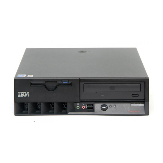
This section shows the various external connectors on the computer to which you can attach external devices. Cover keylock (some models) Optical drive Hard disk drive activity indicator Power-on indicator Power button © Copyright IBM Corp. 2005 USB connectors (2) Microphone connector (line in) Headphone connector (line out) Diskette drive... -
Page 30: Locating Connectors On The Rear Of The Computer
Locating connectors on the rear of the computer The following illustration shows locations of connectors on the rear of the computer. Power cord connector Cable lock latch Rope clip (U-bolt) holes PCI adapter slots Serial connectors (2) Ethernet connector USB connectors (2) Note: Some connectors on the rear of the computer are color-coded to help determine where to connect the cables. -
Page 31: Opening The Cover
Opening the cover Attention: Read “Safety information” on page 153 and “Handling electrostatic discharge-sensitive devices” on page 156 before opening the cover. To open the cover: 1. Shut down your operating system, remove any media (diskettes, CDs, or tapes) from the drives, and turn off all attached devices and the computer. 2. -
Page 32: Locating Components
Locating components The following illustration will help you locate the various components in the computer. Cover Power supply Optical drive Hard disk drive Rotating drive bay assembly Front plastic bezel Diskette drive Hardware Maintenance Manual Heat sink Microprocessor System board Memory module PCI riser assembly Chassis... -
Page 33: Accessing System Board Components And Drives
Accessing system board components and drives To access some components on the system board such as memory, the battery, and the Clear CMOS/BIOS recovery jumper, you might need to rotate the drives upward. You can also use this procedure to access the drives when updating to different or higher capacity drives. -
Page 34: Identifying Parts On The System Board
The system board (sometimes called the planar or motherboard) is the main circuit board in the computer. It provides basic computer functions and supports a variety of devices that are IBM-installed or that you can install later. The following illustration shows the locations of parts on the system board. -
Page 35: Replacing Memory
Replacing memory The computer has two connectors for installing dual inline memory modules that provide up to a maximum of 2 GB of system memory. When installing memory, the following rules apply: v Use 2.5 V, 184-pin, double data rate static random access memory (DDR SDRAM), non-ECC memory modules. -
Page 36: Replacing A Pci Adapter
Replacing a PCI adapter This section provides information and instructions for removing and replacing a PCI adapter. The computer has a riser card with two PCI expansion slots. To remove and replace a PCI adapter: 1. Turn off the computer and disconnect the power cord from the electrical outlet and from the computer. -
Page 37: Replacing The Battery
Note: When the computer is turned on for the first time after battery 10. Turn on the computer and all attached devices. 11. Use the IBM Setup Utility program to set the date and time and any passwords. replacement, an error message might be displayed. This is normal after replacing the battery. -
Page 38: Replacing The Power Supply
Replacing the power supply 1. Turn off the computer and disconnect the power cord from the electrical outlet and from the computer. 2. Disconnect all other cables attached to the computer. 3. Remove the four screws at the rear of the chassis. 4. - Page 39 8. Install the new power supply assembly into the chassis so that the screw holes in the power supply assembly align with those in the chassis. Note: Use only the screws provided by IBM. 9. Install and tighten the four power supply assembly screws into the rear of the chassis.
-
Page 40: Replacing The System Board, Microprocessor, And Heat Sink
13. Ensure that all components have been reassembled correctly and that no tools or loose screws are left inside the computer. 14. Lower the drive bay assembly. 15. Go to “Closing the cover and connecting the cables” on page 46. Replacing the system board, microprocessor, and heat sink Attention: If the computer has been turned off for a long period of time the thermal grease between the microprocessor heat sink and the microprocessor might... - Page 41 4. While holding the left rear of the computer chassis down, pull upward on the handle provided, to remove the PCI riser card assembly along with any adapters. 5. Remove the plastic cover from the microprocessor heat sink 1 . 6.
- Page 42 Figure 2. Microprocessor 10. Remove the microprocessor 2 from the system board by lifting the small handle 1 on the microprocessor. Carefully lift the microprocessor out of the socket. v If you are installing a new system board assembly, continue at Step 11. v If you are replacing only the microprocessor, go to “Replacing the microprocessor”...
- Page 43 15. Using the two blue handles provided, lift the system board assembly out of the computer. Note: You will have to tilt the system board assembly and move it around the edge of the power supply assembly to remove it from the computer. 16.
-
Page 44: Replacing The Microprocessor
Replacing the microprocessor To replace the microprocessor, do the following: 1. Make sure that the handle used to remove the microprocessor is fully in the up position. Otherwise the microprocessor pins might be damaged when installing the microprocessor. 2. Position the microprocessor so that the pins are aligned with the socket and with the beveled corner in the orientation as shown in Figure 2 on page 36. - Page 45 When you install an internal drive, it is important to note the type of drive that you are installing. The following illustrations show a parallel ATA IDE hard disk drive and a serial ATA IDE hard disk drive. Parallel ATA IDE drive Serial ATA IDE drive Listed below are the various types of drives and the connector used to connect them to the system board.
-
Page 46: Replacing A Cd-Rom, Cd-Rw, Or Dvd Optical Drive
Replacing a CD-ROM, CD-RW, or DVD optical drive 1. Open the cover. See “Opening the cover” on page 25. 2. Rotate the drive bay upward to gain access to the cable connections. See “Accessing system board components and drives” on page 27 and “Locating components”... -
Page 47: Connecting A Serial Ata Hard Disk Drive
4. Disconnect the signal and power cables from the hard disk drive. 5. Rotate the hard disk drive and bracket to the rear by pulling on the blue handle provided in the direction of the arrow. 6. Lift the hard disk drive and bracket up to remove. The drive is removed from the bracket by flexing the bracket. -
Page 48: Replacing The Diskette Drive
Replacing the diskette drive 1. Open the cover. See “Opening the cover” on page 25. 2. Slide the blue plastic drive lock to the unlocked position. 3. Slide the drive towards the rear of the computer far enough to gain access to the flat cable connector on the drive. -
Page 49: Replacing The Speaker
6. Lower the drive bay into the normal position. 7. Go to “Closing the cover and connecting the cables” on page 46. Replacing the speaker To replace the speaker: 1. Turn off the computer and disconnect the power cord from the electrical outlet and from the computer. -
Page 50: Replacing The Fan Assembly
1. Turn off the computer and disconnect the power cord from the electrical outlet and from the computer. 2. Open the cover. See “Opening the cover” on page 25. 3. Rotate the drive bay assembly upward to gain access to the power button and LED assembly. - Page 51 6. Remove the plastic insert behind the bezel by releasing the tabs as shown: 7. Remove the fan assembly by releasing the tabs out as shown. 8. Install the new fan assembly and connect the fan cable to the system board. 9.
-
Page 52: Closing The Cover And Connecting The Cables
24. 8. If you have replaced the system board, you must update (flash) the BIOS. See “Flash update procedures” on page 148. 9. To update the configuration, see “Starting the IBM Setup Utility program” on page 19. Hardware Maintenance Manual... -
Page 53: Copyright Ibm Corp
On/Off Switch Power Supply connector v System Board Power Supply connectors v Microprocessor(s) connection Check the power cord for continuity. © Copyright IBM Corp. 2005 FRU/Action Check the configuration and ensure the start-up drive is in the boot sequence. - Page 54 Check/Verify Check the power-on switch for continuity. Hardware Maintenance Manual FRU/Action Power-on Switch...
-
Page 55: Diagnostic Error Codes
Diagnostic error codes Refer to the following diagnostic error codes when using the diagnostic tests. See “Running diagnostics tests” on page 13 for the specific type for information about the Diagnostic programs. In the following index, X can represent any number. Diagnostic Error Code 000-000-XXX BIOS Test Passed... - Page 56 2. Re-start the test to reset the log file 1. Make sure the component that is called out is connected and/or enabled. See Chapter 5, “Using the IBM Setup Utility,” on page 19 2. Re-run test 3. Replace the component that is called out in warning statement 4.
- Page 57 2. Re-start the test to reset the log file 1. Make sure the component that is called out is connected and/or enabled. See Chapter 5, “Using the IBM Setup Utility,” on page 19 2. Re-run test 3. Replace the component that is called out in warning statement 4.
- Page 58 Hardware Maintenance Manual FRU/Action 1. If a component is called out, make sure it is connected and/or enabled. See Chapter 5, “Using the IBM Setup Utility,” on page 19 2. Flash the system and retest. See “Flash update procedures” on page 148 3.
- Page 59 Diagnostic Error Code 001-278-XXX System IRQ11 failure 001-279-XXX System IRQ12 failure 001-280-XXX System IRQ13 failure 001-281-XXX System IRQ14 (hard disk drive) failure 001-282-XXX System IRQ15 failure 001-286-XXX 001-287-XXX 001-288-XXX System Timer failure 001-292-XXX System CMOS RAM error 001-293-XXX System CMOS Battery 001-298-XXX System RTC date/time update failure 001-299-XXX...
- Page 60 2. Re-start the test to reset the log file 1. Make sure the component that is called out is connected and/or enabled. See Chapter 5, “Using the IBM Setup Utility,” on page 19 2. Re-run test 3. Replace the Replace the component that is called out in warning statement 4.
- Page 61 Diagnostic Error Code 005-2XX-XXX 005-3XX-XXX Video subsystem error 006-000-XXX Diskette interface Test Passed 006-0XX-XXX Diskette interface error 006-195-XXX Diskette interface Test aborted by user 006-196-XXX Diskette interface test halt, error threshold exceeded 006-197-XXX Diskette interface test warning 006-198-XXX Diskette interface test aborted 006-199-XXX Diskette interface test failed, cause unknown 006-25X-XXX...
- Page 62 2. Re-start the test to reset the log file 1. Make sure the component that is called out is connected and/or enabled. See Chapter 5, “Using the IBM Setup Utility,” on page 19 2. Re-run test 3. Replace the component that is called out in warning statement 4.
- Page 63 2. Re-start the test to reset the log file 1. Make sure the component that is called out is connected and/or enabled. See Chapter 5, “Using the IBM Setup Utility,” on page 19 2. Re-run test 3. Replace the component that is called out in warning statement 4.
- Page 64 2. Re-start the test to reset the log file 1. Make sure the component that is called out is connected and/or enabled. See Chapter 5, “Using the IBM Setup Utility,” on page 19 2. Re-run test 3. Replace the component that is called out in warning statement 4.
- Page 65 2. Re-start the test to reset the log file 1. Make sure the component that is called out is connected and/or enabled. See Chapter 5, “Using the IBM Setup Utility,” on page 19 2. Re-run test 3. Replace the component that is called out in warning statement 4.
- Page 66 Hardware Maintenance Manual FRU/Action 1. Make sure the component that is called out is connected and/or enabled. See Chapter 5, “Using the IBM Setup Utility,” on page 19 2. Re-run test 3. Replace the component that is called out in warning statement 4.
- Page 67 FRU/Action 1. Make sure the component that is called out is connected and/or enabled. See Chapter 5, “Using the IBM Setup Utility,” on page 19 2. Re-run test 3. Replace the component that is called out in warning statement 4.
- Page 68 Hardware Maintenance Manual FRU/Action 1. Make sure the component that is called out is connected and/or enabled. See Chapter 5, “Using the IBM Setup Utility,” on page 19 2. Re-run test 3. Replace the component that is called out in warning statement 4.
- Page 69 2. Re-start the test to reset the log file 1. Make sure the component that is called out is connected and/or enabled. See Chapter 5, “Using the IBM Setup Utility,” on page 19 2. Re-run test 3. Replace the component that is called out in warning statement 4.
- Page 70 2. Re-start the test to reset the log file 1. Make sure the component that is called out is connected and/or enabled. See Chapter 5, “Using the IBM Setup Utility,” on page 19 2. Re-run test 3. Replace the component that is called out in warning statement 4.
- Page 71 Microprocessor test failed, cause unknown FRU/Action 1. Make sure the component that is called out is connected and/or enabled. See Chapter 5, “Using the IBM Setup Utility,” on page 19 2. Re-run test 3. Replace the component that is called out in warning statement 4.
- Page 72 2. Re-start the test to reset the log file 1. Make sure the component that is called out is connected and/or enabled. See Chapter 5, “Using the IBM Setup Utility,” on page 19 2. Re-run test 3. Replace the component that is called out in warning statement 4.
- Page 73 Diskette Drive error FRU/Action 1. Make sure the component that is called out is connected and/or enabled. See Chapter 5, “Using the IBM Setup Utility,” on page 19 2. Re-run test 3. Replace the component that is called out in warning statement 4.
- Page 74 Diagnostic Error Code 215-000-XXX CD-ROM Drive Test Passed 215-XXX-XXX CD-ROM Drive error 217-000-XXX Hard Disk Drive Test Passed 217-25X-XXX 217-26X-XXX Hard Disk Drive (IDE) error 217-28X-XXX 217-29X-XXX Hard Disk Drive (SCSI) error 220-000-XXX Hi-Capacity Cartridge Drive Test Passed 220-XXX-XXX Hi-Capacity Cartridge Drive error 301-XXX-XXX Keyboard error 301-000-XXX...
- Page 75 Diagnostic Error Code 415-000-XXX Modem Test Passed 415-XXX-XXX Modem error FRU/Action 1. No action 1. Remove the Modem and re-test the system Chapter 7. Symptom-to-FRU Index...
-
Page 76: Beep Symptoms
Beep symptoms Beep symptoms are short tones or a series of short tones separated by pauses (intervals without sound). See the following examples. Beeps 1-2-X Use the following table to diagnose beep symptoms. Beep Symptom 1-1-3 CMOS read-write error 1-2-2-3 ROM BIOS check error 1-2-1 Programmable Interval Timer failed... - Page 77 Beep Symptom 2-2-4 CMOS configuration info validation failed 2-3-1 Screen initialization failed 2-3-2 Screen memory failed 2-3-3 Screen retrace failed 1-2 Search for video ROM failed All other beep code sequences Continuous beep Repeating short beeps FRU/Action 1. Battery 2. System Board 1.
-
Page 78: No-Beep Symptoms
No-beep symptoms Symptom/Error No beep during POST but computer works correctly. No beep during POST. Hardware Maintenance Manual FRU/Action 1. System Board 1. See “Undetermined problems” on page 2. System Board 3. Memory Module 4. Any Adapter or Device 5. Riser Card 6. -
Page 79: Post Error Codes
POST error codes Each time you power-on the system, it performs a series of tests that check the operation of the system and some options. This series of tests is called the Power-On Self-Test, or POST. POST does the following operations. v Checks some basic system-board operations v Checks the memory operation v Starts the video operation... - Page 80 1. Run Setup. Check to see that Ethernet ™ N error 2. System Board 1. C2 Security 1. Run the IBM Setup Utility program. 2. System Board 1. Covers were removed from the 1. System Board the battery” on page 31) changed location? If not, suspect that device.
- Page 81 1. Unsupported Memory 1. L2 Cache Memory 2. System Board 1. Run Setup. Check System Summary menu for memory. (See “Starting the IBM Setup Utility program” on page 19.) 2. Run the Extended Memory Diagnostic tests. 1. Keyboard 2. Keyboard Cable 3.
- Page 82 POST Error Code With an 8603 error With no 8603 error Not listed above And able to run diagnostics POST cannot unlock the diskette drive 662 Configuration Change has occurred Not listed above Math coprocessor configuration error Not listed above Hardware Maintenance Manual FRU/Action 1.
- Page 83 POST Error Code Parallel port configuration error 1047 107X Check SCSI terminator installation 1101 Serial connector error, possible system board failure 1101, 1102, 1106, 1108, 1109 1107 1102 Card selected feedback error 1103 Port fails register check 1106 Serial option cannot be turned off 1107 1110 Register test failed...
- Page 84 1. SDLC Adapter 1. Run FDISK to ensure at least one active partition is set active 1. 36/38 Workstation Adapter 1. Run Setup. (See “Starting the IBM Setup Utility program” on page 19.). 1. Hard Disk Drive 2. System Board 3.
- Page 85 POST Error Code 1804 PCI/PnP Error! Not Enough Real Memory Space Available 1805 PCI/PnP Error! Adapter ROM Checksum Error 180X, 188X PCI configuration or resource error 1962 No operating system found 209X 20XX Not listed above 21XX 2401, 2402 If screen colors change 2401, 2402 If screen colors are OK 2409...
- Page 86 POST Error Code 46XX Not listed above 5600 5962 An IDE device (other than hard drive) configuration error 62XX 63XX 64XX 71XX 74XX 76XX 78XX 79XX 80XX 84XX 8601, 8602 8603, 8604 Pointing Device Error 86XX Not listed above 89XX 91XX 96XX Hardware Maintenance Manual...
- Page 87 3. External DAA (if installed) 4. Modem 1. Run Diagnostics and verify the correct operation of the modem slot 2. Modem 1. Diagnostics detected a non-IBM modem 2. Modem 1. Check PSTN Cable 2. External DAA (if installed) 3. Modem 1.
- Page 88 POST Error Code 10455, 10456 Controller error 10459 Drive diagnostic command error 10461 Drive format error 10462 Controller seek error 10464 Hard Drive read error 10467 Drive non-fatal seek error 10468 Drive fatal seek error 10469 Drive soft error count exceeded 10470, 10471, 10472 Controller wrap error 10473...
- Page 89 POST Error Code 112XX This adapter does not have cache 119XX 121XX 136XX 137XX 141XX 143XX 14710, 14711 148XX 14901, 14902, 1491X, 14922 14932 161XX 164XX 16500 16520, 16540 166XX, 167XX FRU/Action 1. SCSI Adapter 2. Any SCSI Device 3. System Board 4.
- Page 90 POST Error Code 18001 to 18029 18031 to 18039 185XXXX 20001 to 20003 20004 20005 to 20010 200XX Not listed above 20101 to 20103 20104 20105 to 20110 Image Adapter/A Memory Test failure indicated by graphic of adapter 206XX 208XX Verify there are no duplicate SCSI ID settings on the same bus.
- Page 91 POST Error Code Tape Drive amber LED remains on Tape Drive green ″in use″ LED fails to come Tape automatically ejected from drive SCSI ID on rotary switch does not match SCSI ID set in configuration. Verify drive switches inside cover are set to zero Tape sticks or breaks in drive.
- Page 92 27880 to 27889 999030X Hard disk reset failure Hardware Maintenance Manual FRU/Action 1. Remove redundant adapters, run Auto IBM program, then retest. 1. WMSELF.DGS diagnostics file is missing 2. WMSELF.DGS diagnostics file is incorrect 1. 3V Lithium Backup Battery 2. ServerGuard Adapter 1.
-
Page 93: Miscellaneous Error Messages
Wake on LAN 3. Ensure Wake On LAN feature is enabled in Setup/Configuration (see “Starting the IBM Setup Utility program” on page 19) 4. Ensure network administrator is using correct MAC address 5. Ensure no interrupt or I/O address conflicts 6. - Page 94 Message/Symptom ″Insert a Diskette″ icon appears with a known-good diagnostics diskette in the first 3.5-inch diskette drive. Intensity or color varies from left to right of characters and color bars No power or fan not running Non-system disk or disk error-type message with a known-good diagnostic diskette.
-
Page 95: Undetermined Problems
1. Power-off the computer. 2. Remove or disconnect the following components (if installed) one at a time. a. Non-IBM devices b. External devices (modem, printer, or mouse) c. Any adapters d. - Page 96 Hardware Maintenance Manual...
-
Page 97: Chapter 8. Parts Listing
Power supply 200 W (all models) CD-ROM Drive 48X (Black) - w/o volume ctrl and headphone jack (models 11M) CD-ROM Drive 48X (Black) - w/o volume ctrl and headphone jack (models 11M) © Copyright IBM Corp. 2005 8127 FRUs FRU#... - Page 98 Item # CD-ROM Drive 48X (Black) - w/o volume ctrl and headphone jack (models 11M) CD-ROM Drive 48X (Black) - w/o volume ctrl and headphone jack (models 11M) CD-ROM Drive 48X (Black) - w/o volume ctrl and headphone jack (models 11M) CD-ROM Drive 48X (Black) (models 11M) CD-ROM Drive 48X (Black) (models 11M) CD-ROM Drive 48X (Black) (models 11M)
- Page 99 The FRUs listed in the following table are not illustrated. Tool-less hardfile tray (all models) Cable, pwr/LED (all models) Lock assembly (Random keyed) (models 11M) Internal plastic kit (all models) Cable, optical 1-drop ATA 100 (all models) Cable, 2-drop ATA 100 (all models) Cable, SATA (all models) Speaker assembly (all models) system board tray (all models)
- Page 100 Power cord (models) Power cord (models) Power cord (models) Power cord (models) Power cord (models) Power cord (models) Power cord (models) Power cord (models) Power cord (models) Power cord (models) Power cord (models) 8127 Windows XP Pro Recovery CDs US (models 11M) FR (models) GR (models) IT (models)
-
Page 101: Machine Type 8183
Machine Type 8183 Item # Cover (all models) Power supply 200 W (all models) CD-ROM Drive 48X (Black) (All models EXCEPT those otherwise listed) CD-ROM Drive 48X (Black) (All models EXCEPT those otherwise listed) CD-ROM Drive 48X (Black) (All models EXCEPT those otherwise listed) CD-ROM Drive 48X (Black) (All models EXCEPT those otherwise listed) CD-ROM Drive 48X (Black) - w/o volume ctrl and headphone jack (models 47U 45G ADU ADS ADP ADY D2B D2H B4U 79G AEU AES AEP AEY B7U B7F 8FJ... - Page 102 Item # CD-ROM Drive 48X (Black) - w/o volume ctrl and headphone jack (models 47U 45G ADU ADS ADP ADY D2B D2H B4U 79G AEU AES AEP AEY B7U B7F 8FJ 8GJ 8HE 8HJ 8JJ 8LJ 8MJ 8PJ 8QJ 8RJ 8SJ D4S D4Y D5S D5P D5Y B7S B7Y AFJ AGJ AJS AJY AKU ALU ALS ALY B8G BAU BDK BEA BET BEV BFU BFS BFY BGA BGT BGC BGB BGH D7U D7F D7S D7P D7Y D7G D7M D7A D7T D7C D7B D7H D7V D7K D7J D8A D8T D8V D9U D9S D9Y DAC DAB DAH DEU DES DEY...
- Page 103 Item # CD-ROM Drive 48X (Black) (models 47U 45G ADU ADS ADP ADY D2B D2H B4U 79G AEU AES AEP AEY B7U B7F 8FJ 8GJ 8HE 8HJ 8JJ 8LJ 8MJ 8PJ 8QJ 8RJ 8SJ D4S D4Y D5S D5P D5Y B7S B7Y AFJ AGJ AJS AJY AKU ALU ALS ALY B8G BAU BDK BEA BET BEV BFU BFS BFY BGA BGT BGC BGB BGH D7U D7F D7S D7P D7Y D7G D7M D7A D7T D7C D7B D7H D7V D7K D7J D8A D8T D8V D9U D9S D9Y DAC DAB DAH DEU DES DEY G3B G3H G6J G7J 7CG 47S 47Y AMJ APJ...
- Page 104 Item # Universal Combo Drive (48x/32x/48x/16x) (models CTO-U CTO-G DGU G4U DJJ BMU ANJ AQJ DNJ DQJ GCJ BSU 69J 6AJ GKU GLU H3U DVJ DYJ GQJ GSJ GUU GVU H7U) Universal Rambo drive (Black) (models G9J GTJ) Rambo III drive (Black) (optional to 26K5377) (models G9J) Rambo IV drive (Black) (models GDJ GTJ) HDD 40GB 7200 rpm EIDE (All models EXCEPT 4KM 4KA 4KC 4KC 4KH 4KR 4KK 4JG 4JM 4JA 4JC 4JH 4JR B2U D4S D4Y D5S D5P D5Y 8TJ G5C G4U G9J)
- Page 105 Item # Intel P4 2.66 GHz (models 21U CBU 21F 21S 21P 21Y 21G 21M 21A 21T 21C 21B 21H 21V 21J 22U 22S 22P 22Y 23U 24U 24S 24P 24Y 2AU 2AF 2AS 2AP 2AY 2BG 73G 21K 2DC 2DV 2JU) Intel P4 2.8 GHz (models CCU 32U 32F 32S 32P 32Y 33U 33S 33P 33Y 34U 35G 74G 75G 3GG B7U B7F B7S B7Y BHC 34F) Intel P4 3.06 GHz (models 46G 76G 46U D5S D5P D5Y D6S D6Y 8TJ)
- Page 106 Item # System board, 10/100 E-net, no POV (Prescott CPU enabled) (optional to 89P7950) (models 4HM 4HA 4HC 4HH 4HV ADU ADS ADP ADY B2U B3S B3P B3U B3Y 78G 79G AEU AES AEP AEY B5U B6U D3U 7AG 7BG CPU CQU 8LJ BHC C2U 21U 41U CAU CBU CCU CDU CTO A1U A1S A1P A1Y A2G 12U 12S 12P 12Y 13U 51U 51F 51S 51P 51Y 52U 52S 52P 52Y 53U 53S 53P 53Y 55G 21F 21S 21P 21Y 21G 21M 21A 21T 21C 21B 21H 21V 21J 22U 22S 22P 22Y 24U 24S 24P 24Y 32U...
- Page 107 Item # System board, Gigabit E-net, POV (models A4J A5J A6J A7J A8J 1AE 1AJ 1BJ 1CJ 1DJ 1EJ 1FJ 2BG 39J 3AJ 3BJ 3CJ 3DJ 3EJ 48G CEJ CFJ CGJ CHJ A9J 29U 3FG 1AM 2FM 39M 4KM 4KA 4KC 4KC 4KH 4KR 4KK 81J 82J 83J 84J 85J 86J 87J 88J 89J 8AJ 8BJ 8CJ 8DJ 8EJ CJJ 2HM B1M D1M D2B D2H 8FJ 8GJ 8HE 8HJ 8JJ 8KJ 8LJ 8MJ 8NJ 8PJ 8QJ 8RJ 8SJ CTJ D6S D6Y 43U 43F 43S 43P 43Y 43G 43M 43A 43T 43C 43B 43H 43V 43K 43J 8TJ DJJ AMJ ANJ APJ AQJ DMJ DNJ DPJ DQJ GAJ GBJ GCJ G9J...
- Page 108 The FRUs listed in the following table are not illustrated. Tool-less hardfile tray (all models) Cable, pwr/LED (all models) Lock assembly (Random keyed) (models 7FG AMJ ANJ APJ AQJ DMJ DNJ DPJ DQJ GAJ GBJ GCJ GDJ 64J 65J 66J 67J 68J 69J 6AJ DTU DTG DUE DUJ DVJ DWJ DYJ GMU GNU GNF GNS GNP GNL GNY GNG GNM GNA GNQ GNT GNC GNB GNH GNV GNK GNJ GPJ GQJ GRJ GSJ GTJ H4U H4F H5G H6C A4J A5J A6J A7J A8J 1AE 1AJ 1BJ 1CJ 1DJ 1EJ 1FJ 2AU 2AF 2AS 2AP 2AY 2BG 39J 3AJ 3BJ 3CJ 3DJ 3EJ 43U 43F 43S 43P 43Y 43G 43M...
- Page 109 Mouse, 3 button wheel (models A2G 55G 35G 46G 45G A4J A5J A6J A7J A8J 1AE 1AJ 1BJ 1CJ 1DJ 1EJ 1FJ 39J 3AJ 3BJ 3CJ 3DJ 3EJ 71G 72G 73G 74G 75G 76G A9J 1GM 2EM 3LM 3MM 1AM 2FM 39M 46U AAG 3GG 2HM B1M D1M 78G 79G 81J 82J 83J 84J 85J 86J 87J 88J 89J 8AJ 8BJ 8CJ 8DJ 8EJ 8FJ 8GJ 8HE 8HJ 8JJ 8KJ 8LJ 8MJ 8NJ 8PJ 8QJ 8RJ 8SJ 7AG 7BG 8LJ AFJ AGJ AHJ G6J G7J G8J DJJ B8G 7CG G9J AMJ ANJ APJ AQJ DMJ DNJ DPJ DQJ GAJ GBJ GCJ GDJ 64J 65J 66J 67J 68J 69J 6AJ DUE DUJ DVJ DWJ DYJ GPJ GQJ GRJ...
- Page 110 8183 (Preferred Pro) Keyboards Bulgarian (models A2G 55G 21G 35G 46G 45G 2BG 43G 48G 71G 72G 73G 74G 75G 76G 3FG 3JG 4GG AAG 3GG 3JG 4GG 4JG 78G 79G 7AG 7BG B8G BBG D7G DCG 7CG 7DG 7EG 7FG DSG GFG H1G DTG GNG H5G) Chinese/US (models 16B 26B 27B 21B 21V 43B 43V 4HV 3HB 2DV 4HV D2B BEV BGB D7B D7V D8V DAB G3B GMB GNB GNV GWB) Czech (models A2G 55G 21G 35G 46G 45G 2BG 43G 48G 71G 72G 73G 74G 75G 76G 3FG...
- Page 111 8183 (Preferred Pro) Keyboards LA Spanish (models A1S A1Y 12S 12Y 51S 51Y 52S 52Y 53S 53Y 21S 21Y 22S 22Y 24S 24Y 32S 32Y 33S 33Y 2AS 2AY 43S 43Y A3S A3Y 26S 26Y 36S 36Y ABS ABY 11S 11Y 15S 15Y ADS ADY B3S B3Y AES AEY D4S D4Y D5S D5Y B7S B7Y D6S D6Y AJS AJY ALS ALY B9S B9Y BCS BCY BFS BFY D7S D7Y D9S D9Y DES DEY DFS DFY 47S 47Y BPS DRS GNS GNY)
- Page 112 8183 (Preferred Pro) Keyboards Yugoslav/Latin (models A2G 55G 21G 35G 46G 45G 2BG 43G 48G 71G 72G 73G 74G 75G 76G 3FG 3JG 4GG AAG 3GG 3JG 4GG 4JG 78G 79G 7AG 7BG B8G BBG D7G DCG 7CG 7DG 7EG 7FG DSG GFG H1G DTG GNG H5G) Brazil/Portugese (models A1P 12P 51P 52P 53P 21P 22P 24P 32P 33P 2AP 43P A3P 26P 36P ABP 11P 15P ADP B3P AEP D5P D7P BPP DRP GNP) Power cord (models AEU AES AEP B5U B6U D3U G2U B7U B7F CRU CSU D4S D5S D5P...
- Page 113 Power cord (models A2G 55G 21G 35G 46G 45G 2BG 43G 48G 71G 72G 73G 74G 75G 76G 3FG 3JG 4GG AAG 3GG 78G 79G 7AG 7BG B8G BBG D7G DCG 7CG 7DG 7EG 7FG DSG GFG H1G DTG GNG H5G) Power cord (models A2G 55G 21G 21A 35G 46G 45G 2BG 43G 43A 48G 71G 72G 73G 74G 75G 76G 3FG 3JG 4GG AAG 3GG 78G 79G 7AG 7BG B8G BBG D7G DCG 7CG 7DG 7EG 7FG DSG GFG H1G DTG GNG H5G)
- Page 114 8183 Windows XP Pro Recovery CDs DK (models 21G 2BG 35G 3FG 3GG 3JG 43G 45G 46G 48G 4GG 4JG 55G 71G 72G 73G 74G 75G 76G A2G AAG 78G 79G 7AG 7BG B8G BBG D7G DCG 7CG 7DG 7EG 7FG DSG GFG H1G DTG GNG H5G) NL (models 21G 2BG 35G 3FG 3GG 3JG 43G 45G 46G 48G 4GG 4JG 55G 71G 72G 73G 74G 75G 76G A2G AAG 78G 79G 7AG 7BG B8G BBG D7G DCG 7CG 7DG 7EG 7FG DSG...
-
Page 115: Machine Type 8184
8183 Windows XP Pro Recovery CDs Multilingual RCD 1 XP-P (models 7AG 7BG B8G BBG D7G DCG 7CG 7DG 7EG 7FG DSG GFG H1G DTG GNG H5G) Multilingual RCD 2 XP-P (models 7AG 7BG B8G BBG D7G DCG 7CG 7DG 7EG 7FG DSG GFG H1G DTG GNG H5G) 8183 Windows XP Home Recovery CDs CS (model 2DC BHC) - Page 116 Item # CD-ROM Drive 48X (Black) (models 21U 21F 21S 21P 21Y 21G 21M 21A 21T 21C 21B 21H 21V 21J 21K) CD-ROM Drive 48X (Black) (models 21U 21F 21S 21P 21Y 21G 21M 21A 21T 21C 21B 21H 21V 21J 21K) CD-ROM Drive 48X (Black) (models 21U 21F 21S 21P 21Y 21G 21M 21A 21T 21C 21B 21H 21V 21J 21K) CD-ROM Drive 48X (Black) (models 21U 21F 21S 21P 21Y 21G 21M 21A 21T 21C...
- Page 117 Item # Universal Combo Drive (48x/24x/48x/16x) -- optional to 26K5379 and 26K5381 (models G2M) Universal Combo Drive (48x/32x/48x/16x) (models G2M) Universal Combo Drive (48x/32x/48x/16x) (models G2M) Universal Combo Drive (48x/32x/48x/16x) (models G2M) Universal Combo Drive (48x/32x/48x/16x) (models G2M) HDD 40GB EIDE (models 21U 21F 21S 21P 21Y 21G 21M 21A 21T 21C 21B 21H 21V 21J 43U 43F 43S 43P 43Y 43G 43M 43A 43T 43C 43B 43H 43V 43J 21K 43K 36U 36F 36S 36P 36Y 36G 36M 36A 36T 36C 36B 36H 36V 36K 36J A1M B1M D1M A2M B2M D2M B3M B4M D3M D4M D7U D7F D7S D7P D7Y D7G D7M D7A...
- Page 118 Item # System board, Gigabit E-net, no POV (Prescott CPU enabled) (models 36U 36F 36S 36P 36Y 36G 36M 36A 36T 36C 36B 36H 36V 36K 36J A1M B1M D1M A2M B2M D2M) System board, Gigabit E-net, POV (Prescott CPU enabled) (models 32U 32F 32S 32P 32L 32Y 32G 32M 32A 32Q 32T 32C 32B 32H 32V 32K 32J) System board, Gigabit E-net, POV (Prescott CPU enabled) (models 32U 32F 32S 32P 32L 32Y 32G 32M 32A 32Q 32T 32C 32B 32H 32V 32K 32J)
- Page 119 Fan Baffle for Prescott CPU (models B3M B4M D3M D4M D7U D7F D7S D7P D7Y D7G D7M D7A D7T D7C D7B D7H D7V D7K D7J A1M 32U 32F 32S 32P 32L 32Y 32G 32M 32A 32Q 32T 32C 32B 32H 32V 32K 32J G1M G2M) Battery (all models) Monitor cable (all models) Dongle (all models)
- Page 120 8184 (Preferred Pro) Keyboards Korean (models 21K 43K 36K D7K 32K) LA Spanish (models 21S 21Y 43S 43Y 36S 36Y D7S D7Y 32S 32Y) Norwegian (models 21G 43G) Polish (models 21G 43G 36G D7G 32G) Portugese (models 21G 43G 36G D7G 32G) Romanian (models 21G 43G 36G D7G 32G) Russian (models 21G 36G 43G Russian/Cyrillic (models 21G 43G 36G D7G 32G)
- Page 121 8184 Windows XP Pro Recovery CDs FR (models 21G 43G 36G) GR (models 21G 43G 36G) IT (models 21G 43G 36G) SP (models 21S 21Y 21G 43S 43Y 43G 36S 36Y 36G D7S D7Y D7G 32S 32Y 32G) BR (models 21G 43G 36G) DK (models 21G 43G 36G) NL (models 21G 43G 36G) AE (models 21G 43G 36G)
-
Page 122: Machine Type 8320
Machine Type 8320 Item # Cover (all models) Power supply 200 W (all models) CD-ROM Drive 48X (Black) (models A1J A3J A4J A6J A7J A9J 12J 13J 15J 16J 18J 1CJ ABU ACU ADS ADP AEU ADY 1CS 1CP 1CY 1DU 1EU) CD-ROM Drive 48X (Black) (models A1J A3J A4J A6J A7J A9J 12J 13J 15J 16J 18J 1CJ ABU ACU ADS ADP AEU ADY 1CS 1CP 1CY 1DU 1EU) CD-ROM Drive 48X (Black) (models A1J A3J A4J A6J A7J A9J 12J 13J 15J 16J 18J... - Page 123 Item # CD-ROM Drive 48X (Black) - w/o volume ctrl and headphone jack (models 51U 52U 53U 27U 84J 85J 87J 88J 8AJ 8BJ 8CJ 8EJ 8FJ 54M 55M 28M 34M 8KJ 8MJ 56E 56J 57J 5AJ 5BJ 36J 37J 71G 5CJ 5DJ 3CJ 3DJ 74G 75G 77G 5FJ 5GJ 5HJ 5JJ 7AG 7BG 7DG 7FG 7GG AKJ ALJ AMJ ANJ 44J 45J 61J 62J 63J 64J 67J 68J 69J 6AJ) CD-ROM Drive 48X (Black) - w/o volume ctrl and headphone jack (models 51U 52U 53U 27U 84J 85J 87J 88J 8AJ 8BJ 8CJ 8EJ 8FJ 54M 55M 28M 34M 8KJ 8MJ 56E...
- Page 124 Item # Combo drive 48X32X/48X/16X) (models 59J 39J 42B 43C 3FJ 79G 5KJ 5MJ 7JG 7LG AQJ 47J 66J 6CJ) Combo Drive (48x32x/48x/16x) (models 59J 39J 42B 43C 3FJ 79G 5KJ 5MJ 7JG 7LG AQJ 47J 66J 6CJ) Combo Drive (48x32x/48x/16x) (models 59J 39J 42B 43C 3FJ 79G 5KJ 5MJ 7JG 7LG AQJ 47J 66J 6CJ) Combo Drive (48x32x/48x/16x) (models 59J 39J 42B 43C 3FJ 79G 5KJ 5MJ 7JG 7LG AQJ 47J 66J 6CJ)
- Page 125 Item # Intel P4 3.0 GHz (model 41C) Intel Celeron Prescott 2.4 GHz (models 5FJ 5GJ 5HJ 5JJ 5KJ 5LJ 5MJ) Intel Celeron Prescott 2.53 GHz (models 7AG AKJ ALJ AMJ ANJ APJ AQJ) Intel Celeron Prescott 2.66 GHz (models 7BG 7CG) Intel Celeron Prescott 2.8 GHz (models 7DG 7EG 61J 62J 63J 64J 65J 66J) Intel Celeron Prescott 2.93 GHz (models 67J 68J 69J 6AJ 6BJ 6CJ) Intel Prescott P4 2.8 GHz (models 36J 37J 38J 39J 71G CHJ)
- Page 126 Item # 512 MB SDRAM PC3200 (models 7JG 7LG) Riser card assembly (all models) Chassis (all models) The FRUs listed in the following table are not illustrated. Tool-less hardfile tray (all models) Cable, pwr/LED (all models) Lock assembly (Random keyed) (models 72G 73G 78G 79G 7HG 7JG 7KG 7LG) Internal plastic kit (all models) Cable, optical 1-drop ATA 100 (all models) Cable, 2-drop ATA 100 (all models)
- Page 127 Speaker Power brick (newer 2 prong) - China, Hong Kong (models 19B 21B 22C 24C 25C 31C 32C 41C 33B 3AB 3BC 42B 43C) Speaker Power brick - Japan (model A9J 81J 59J 5KJ) RJ11 connector adapter (Spain, Ireland) (All “G” models) RJ11 connector adapter (Austria) (All “G”...
- Page 128 8320 (Preferred Pro) Keyboards Iceland (models 71G 72G 73G 74G 75G 76G 77G 78G 79G 7AG 7BG 7CG 7DG 7EG 7FG 7GG 7HG 7JG 7KG 7LG) Italian 141 (models 71G 72G 73G 74G 75G 76G 77G 78G 79G 7AG 7BG 7CG 7DG 7EG 7FG 7GG 7HG 7JG 7KG 7LG) Italian 142 (models 71G 72G 73G 74G 75G 76G 77G 78G 79G 7AG 7BG 7CG 7DG 7EG 7FG 7GG 7HG 7JG 7KG 7LG)
- Page 129 8320 RAK III Lite keyboard Chinese/US (models 23V 19B 21B 33B 3AB 42B) Power cord (models CAU CBU 23V ABU ACU ADS ADP AEU 1CS 1CP 1DU 1EU 26U 51U 52U 53U 27U 71G 72G 73G 74G 75G 76G 77G 78G 79G 7AG 7BG 7CG 7DG 7EG 7FG 7GG 7HG 7JG 7KG 7LG) Power cord (models 54M 55M 28M 29M 34M 35M) Power cord (models 71G 72G 73G 74G 75G 76G 77G 78G 79G 7AG 7BG 7CG 7DG 7EG...
- Page 130 8320 Windows XP Pro Recovery CDs FR (models 71G 72G 73G 74G 75G 76G 77G 78G 79G 7AG 7BG 7CG 7DG 7EG 7FG 7GG 7HG 7JG 7KG 7LG) GR (models 71G 72G 73G 74G 75G 76G 77G 78G 79G 7AG 7BG 7CG 7DG 7EG 7FG 7GG 7HG 7JG 7KG 7LG) IT (models 71G 72G 73G 74G 75G 76G 77G 78G 79G 7AG 7BG 7CG 7DG 7EG 7FG 7GG 7HG 7JG 7KG 7LG)
-
Page 131: Machine Type 8416
Machine Type 8416 Item # Cover (all models) Power supply 200W (all models) DVD-ROM 16X/48X (Black) (models KUH KFH) DVD-ROM 16X/48X (Black) (models KUH KFH) DVD-ROM 16X/48X (Black) (models KUH KFH) DVD-ROM 16X/48X (Black) (models KUH KFH) HDD 40GB EIDE (models KUH KFH) Rotating bay assembly (all models) Plastic bezel kit (all models) Diskette drive 3.5″, 1.44MB, 3MODE, slim (models KUH KFH) - Page 132 Item # System board, Gigabit E-net, POV (models KUH KFH) System board, Gigabit E-net, POV (Prescott CPU enabled) (optional to 89P7951) (models KUH KFH) System board, Gigabit E-net, POV (Prescott CPU enabled) (optional to 89P7934) (models KUH KFH) 1GB NP SDRAM PC2700 (models KUH KFH) Riser card assembly (all models) Chassis (all models) The FRUs listed in the following table are not illustrated.
-
Page 133: Machine Type 8417
8416 (Preferred Pro) keyboards US English (models KUH) French (models KFH) Power cord (models KUH KFH) 8416 Windows XP Pro Recovery CDs US (models KUH) FR/CF (models KFH) Machine Type 8417 Item # Cover (all models) Power supply 200W (all models) 8416 Power cords 8417 FRUs FRU#... - Page 134 Item # CD-ROM Drive 48X (Black) (models A1G A2G) CD-ROM Drive 48X (Black) (models A1G A2G) CD-ROM Drive 48X (Black) (models A1G A2G) CD-ROM Drive 48X (Black) (models A1G A2G) CD-ROM Drive 48X (Black) - w/o volume ctrl and headphone jack (models A4G A5G A6G 73G 74G 75G 32U 42U 33U 44U A7G A8G A9G AAG 51U 61U) CD-ROM Drive 48X (Black) - w/o volume ctrl and headphone jack (models A4G A5G A6G 73G 74G 75G 32U 42U 33U 44U A7G A8G A9G AAG 51U 61U)
- Page 135 Item # Intel Celeron Prescott 2.8 GHz (models AAG) Intel Prescott P4 2.8GHz (models 33U) Intel Prescott P4 3.0GHz (models 43U 44U) Intel Prescott P4 3.2GHz (models 51U) Intel Prescott P4 3.4GHz (models 61U) System board, 10/100 E-net, no POV (models A1G A2G A4G A5G A6G 71G 73G 74G 75G 31U 41U) System board, 10/100 E-net, no POV (Prescott CPU enabled) (models A4G A5G A6G 71G 73G 74G 75G A1G A2G 31U 41U 43U A7G A8G A9G AAG)
- Page 136 Fan baffle for Prescott CPU models (models 33U 43U 44U A7G A8G A9G AAG 51U 61U) Battery (all models) Monitor cable (all models) Dongle (all models) Universal Adapter Bracket 5.25 to 3.5, No Bezel (for HDD) Mouse, 3 button wheel (models A1G A2G A4G A5G A6G 71G 73G 74G 75G) Optical Wheelmouse (models 31U 32U 41U 42U 33U 43U 44U A7G A8G A9G AAG 51U 61U) RJ11 connector adapter (Spain, Ireland) (All “G”...
- Page 137 8417 (Preferred Pro) keyboards Portugese (models A1G A2G A4G A5G A6G 71G 73G 74G A7G A8G A9G AAG) Romanian (models A1G A2G A4G A5G A6G 71G 73G 74G A7G A8G A9G AAG) Russian (models A1G A2G A4G A5G A6G 71G 73G 74G A7G A8G A9G AAG) Russian/Cyrillic (models A1G A2G A4G A5G A6G 71G 73G 74G A7G A8G A9G AAG) Serbian/Cyrillic (models A1G A2G A4G A5G A6G 71G 73G 74G A7G A8G A9G AAG) Slovak (models A1G A2G A4G A5G A6G 71G 73G 74G A7G A8G A9G AAG)
- Page 138 8417 Windows XP Pro Recovery CDs AE (models A1G A2G A4G A5G A6G 71G 73G 74G 75G A7G A8G A9G AAG) SV (models A1G A2G A4G A5G A6G 71G 73G 74G 75G A7G A8G A9G AAG) HE (models A1G A2G A4G A5G A6G 71G 73G 74G 75G A7G A8G A9G AAG) FI (models A1G A2G A4G A5G A6G 71G 73G 74G 75G A7G A8G A9G AAG) NO (models A1G A2G A4G A5G A6G 71G 73G 74G 75G A7G A8G A9G AAG) PL (models A1G A2G A4G A5G A6G 71G 73G 74G 75G A7G A8G A9G AAG)
-
Page 139: Machine Type 8418
Machine Type 8418 Item # Cover (all models) Power supply 200W (all models) CD-ROM Drive 48X (Black) (models A4G 31G) CD-ROM Drive 48X (Black) (models A4G 31G) CD-ROM Drive 48X (Black) (models A4G 31G) CD-ROM Drive 48X (Black) (models A4G 31G) HDD 40GB EIDE (models A4G 31G) Rotating bay assembly (all models) Plastic bezel kit (all models) - Page 140 Item # Intel P4 2.8 GHz (model 31G) System board, 10/100 E-net, no POV (models A4G 31G) System board, 10/100 E-net, no POV (Prescott enabled) (models A4G 31G) System board, 10/100 E-net, no POV (Prescott enabled) (optional to 89P7933) (models A4G 31G) 128 MB SDRAM (model A4G) 256 MB SDRAM (model 31G) Riser card assembly (all models)
- Page 141 RJ11 connector adapter (Sweden) (All “G” models) RJ11 connector adapter (Switzerland) (All “G” models) 8418 (Preferred Pro) keyboards US English (models A4G 31G) Arabic (models A4G 31G) Belgian/French (models A4G 31G) Belgian/UK (models A4G 31G) Bulgarian (models A4G 31G) Czech (models A4G 31G) Danish (models A4G 31G) Dutch (models A4G 31G) French (models A4G 31G)
- Page 142 Power cord (models A4G 31G) Power cord (models A4G 31G) Power cord (models A4G 31G) Power cord (models A4G 31G) Power cord (models A4G 31G) 8418 Windows XP Pro Recovery CDs US (models A4G 31G) FR (models A4G 31G) GR (models A4G 31G) IT (models A4G 31G) SP (models A4G 31G) DK (models A4G 31G)
-
Page 143: Machine Type 8419
Machine Type 8419 Item # Cover (all models) Power supply 200W (all models) CD-ROM Drive 48X (Black) (models 21U 31U 33U 11U 43U) CD-ROM Drive 48X (Black) (models 21U 31U 33U 11U 43U) CD-ROM Drive 48X (Black) (models 21U 31U 33U 11U 43U) CD-ROM Drive 48X (Black) (models 21U 31U 33U 11U 43U) CD-ROM Drive 48X (Black) - w/o volume ctrl and headphone jack (models 23U 35U 41U 51U A1M 37U 44U 53U) - Page 144 Item # CD-ROM Drive 48X (Black) (models 23U 35U 41U 51U A1M 37U 44U 53U) CD-ROM Drive 48X (Black) (models 23U 35U 41U 51U A1M 37U 44U 53U) CD-ROM Drive 48X (Black) (models 23U 35U 41U 51U A1M 37U 44U 53U) CD-ROM Drive 48X (Black) (models 23U 35U 41U 51U A1M 37U 44U 53U) 48X24X48X CD-RW (Black) (models 22U 32U 34U 12U) CD-RW 48X/32X/48X (models 24U 36U 42U 52U 55M)
- Page 145 Item # Intel Prescott P4 3.2 GHz (models 53U 54U 55M 56M CKU) Intel Prescott P4 3.4 GHz (models 61U CLU) System board, 10/100 E-net, no POV (models 21U 22U 31U 32U 33U 34U CAU CBU CCU CDU 11U 12U CEU CGU 23U 24U) System board, 10/100 E-net, no POV (Prescott CPU enabled) (models 21U 22U 31U 32U 33U 34U CAU CBU CCU CDU 11U 12U CEU CGU 23U 24U 35U 36U 41U 42U 51U 52U 43U 44U 53U 54U 55M 56M 61U CJU CKU CLU)
- Page 146 Mouse, 2 button black (models CAU CBU CCU CDU CEU CGU) Mouse, optical wheel (models 21U 22U 31U 32U 33U 34U 11U 12U 23U 24U 35U 36U 41U 42U 51U 52U 43U A1M 37U 44U 53U 54U 55M 56M 61U) RJ11 connector adapter (Spain, Ireland) (All “G”...
-
Page 147: Machine Type 8429
Machine Type 8429 Item # Cover (all models) Power supply 200W (all models) Optical drive (no models) HDD 40GB EIDE (models 11G 21G 22G 31G 41G) Rotating bay assembly (all models) Plastic bezel kit (all models) Diskette drive 3.5, 1.44 MB, 3mode, slim (models 11G 21G 31G 41G) Diskette drive 3.5, 1.44 MB, 3mode, slim (models 11G 21G 31G 41G) Diskette drive 3.5, 1.44 MB, 3mode, slim (models 11G 21G 31G 41G) Heatsink (all models) - Page 148 Item # System board, 10/100 E-net, no POV (models 11G 21G 22G 31G 41G) System board, 10/100 E-net, no POV (optional to 89P7950) (models 11G 21G 22G 31G 41G) System board, 10/100 E-net, no POV (optional to 89P7933) (models 11G 21G 22G 31G 41G) System board, 10/100 E-net, no POV (Prescott enabled) (models 11G 21G 22G 31G 41G)
- Page 149 RJ11 connector adapter (Switzerland) (All “G” models) 8429 (Preferred Pro) keyboards US English (models 11G 21G 22G 31G 41G) Arabic (models 11G 21G 22G 31G 41G) Belgian/French (models 11G 21G 22G 31G 41G) Belgian/UK (models 11G 21G 22G 31G 41G) Bulgarian (models 11G 21G 22G 31G 41G) Czech (models 11G 21G 22G 31G 41G) Danish (models 11G 21G 22G 31G 41G)
- Page 150 Power cord (models 11G 21G 22G 31G 41G) Power cord (models 11G 21G 22G 31G 41G) Power cord (models 11G 21G 22G 31G 41G) Power cord (models 11G 21G 22G 31G 41G) 8429 Windows XP Pro Recovery CDs US (models 11G 21G 22G 31G 41G) FR/CF (models 11G 21G 22G 31G 41G) GR (models 11G 21G 22G 31G 41G) IT (models 11G 21G 22G 31G 41G)
-
Page 151: Chapter 9. Additional Service Information
Administrator Password v Operating System Password Power-on and Administrator passwords are set in the Setup Utility program. See “Starting the IBM Setup Utility program” on page 19 for information about running the Setup Utility. Power-on password A power-on password denies access to the computer by an unauthorized user when the computer is powered on. -
Page 152: Erasing A Lost Or Forgotten Password (Clearing Cmos)
Configuration/Setup Utility program. Administrator password control The Administrator password is set in the Setup Configuration. Refer to “Starting the IBM Setup Utility program” on page 19. Operating system password An operating system password is very similar to a power-on password and denies access to the computer by an unauthorized user when the password is activated. -
Page 153: Management Information Format (Mif)
Current Level BIOS information – Run the Configuration Utility to determine the level of BIOS installed. v Sources for determining the latest level BIOS available 1. IBM PC support web site: http://www.ibm.com/pc/support/ 2. IBM Support Center 3. Levels 1 and 2 Support 4. -
Page 154: Flash Update Procedures
2. Turn on the computer. If it is on already, you must turn it off and back on again. The update begins. Updating (flashing) BIOS from your operating system Note: Due to constant improvements being made to the IBM Web site, Web page content (including the links referenced in the following procedure) is subject to change. - Page 155 10. Unplug the power cords from electrical outlets. 11. Open the cover. See “Opening the cover” on page 25. 12. Remove any adapters that impede access to the BIOS Configuration jumper. 13. Replace the Clear CMOS/Recovery jumper to its original position. 14.
-
Page 156: Power Management
Setting Automatic Hardware Power Management features 1. Start the Configuration/Setup Utility program (see “Starting the IBM Setup Utility program” on page 19). 2. Select Power Management from the Configuration/Setup Utility program menu. -
Page 157: Automatic Power-On Features
Wake on LAN: If the computer has a properly configured token-ring or Ethernet LAN adapter card that is Wake on LAN-enabled and there is remote network management software, you can use the IBM-developed Wake on LAN feature. When you set Wake on LAN to Enabled, the computer will turn on when it receives a specific signal from another computer on the local area network (LAN). - Page 158 Hardware Maintenance Manual...
-
Page 159: Chapter 10. Related Service Information
Safety information The following section contains the safety information that you need to be familiar with before servicing an IBM computer. General safety Follow these rules to ensure general safety: v Observe good housekeeping in the area of the machines during and after maintenance. -
Page 160: Electrical Safety
Electrical safety CAUTION: Electrical current from power, telephone, and communication cables can be hazardous. To avoid personal injury or equipment damage, disconnect the attached power cords, telecommunication systems, networks, and modems before you open the server/workstation covers, unless instructed otherwise in the installation and configuration procedures. -
Page 161: Safety Inspection Guide
This guide addresses only those items. However, good judgment should be used to identify potential safety hazards due to attachment of non-IBM features or options not covered by this inspection guide. -
Page 162: Handling Electrostatic Discharge-Sensitive Devices
Insulation must not be frayed or worn. 4. Remove the cover. 5. Check for any obvious non-IBM alterations. Use good judgment as to the safety of any non-IBM alterations. 6. Check inside the unit for any obvious unsafe conditions, such as metal filings, contamination, water or other liquids, or signs of fire or smoke damage. -
Page 163: Grounding Requirements
Grounding requirements Electrical grounding of the computer is required for operator safety and correct system function. Proper grounding of the electrical outlet can be verified by a certified electrician. Safety notices (multi-lingual translations) The caution and danger safety notices in this section are provided in the following languages: v English v Brazilian/Portuguese... - Page 164 CAUTION: When replacing the lithium battery, use only IBM Part Number 33F8354 or an equivalent type battery recommended by the manufacturer. If your system has a module containing a lithium battery, replace it only with the same module type made by the same manufacturer. The battery contains lithium and can explode if not properly used, handled, or disposed of.
- Page 165 CAUTION: The power control button on the device and the power switch on the power supply do not turn off the electrical current supplied to the device. The device also might have more than one power cord. To remove all electrical current from the device, ensure that all power cords are disconnected from the power source.
- Page 166 5. LIGUE os dispositivos. CUIDADO: Ao substituir a bateria de lítio, utilize apenas uma bateria IBM, Número de Peça 33F8354 ou uma bateria de tipo equivalente, recomendada pelo fabricante. Se o seu sistema possui um móídulo com uma bateria de lítio, substitua-o apenas pelo mesmo tipo de mídulo, do mesmo fabricante.
- Page 167 Para descartar a bateria, entre em contato com a área de atendimento a clientes IBM, pelo telefone (011) 889-8986, para obter informações sobre como enviar a bateria pelo correio para a IBM. PRECAUCIÓN: Quando produtos a laser (unidades de CD-ROM, unidades de DVD, dispositivos de fibra ítica, transmissores, etc.) estiverem instalados, observe o seguinte:...
- Page 168 CUIDADO: CUIDADO: Não coloque nenhum objeto com peso superior a 82 kg (180 lbs.) sobre dispositivos montados em rack. Hardware Maintenance Manual...
- Page 169 Chapter 10. Related service information...
- Page 170 Hardware Maintenance Manual...
- Page 171 Chapter 10. Related service information...
- Page 172 Hardware Maintenance Manual...
- Page 173 Chapter 10. Related service information...
- Page 174 Hardware Maintenance Manual...
- Page 175 Chapter 10. Related service information...
- Page 176 Hardware Maintenance Manual...
- Page 177 ATTENTION: Remplacez la pile au lithium usagée par une pile de référence identique exclusivement - voir la référence IBM - ou par une pile équivalente recommandée par le fabricant. Si votre système est doté d’un module contenant une pile au lithium, vous devez le remplacer uniquement par un module identique, produit par le même fabricant.
- Page 178 Pour la mise au rebut, reportez-vous à la réglementation en vigueur. ATTENTION: Si des produits laser sont installés (tels que des unités de CD-ROM ou de DVD, des périphériques contenant des fibres optiques ou des émetteurs-récepteurs), prenez connaissance des informations suivantes: v N’ouvrez pas ces produits pour éviter une exposition directe au rayon laser.
- Page 179 ATTENTION: Ne posez pas d’objet dont le poids dépasse 82 kg sur les unités montées en armoire. Chapter 10. Related service information...
- Page 180 4. Netzstecker an Steckdose anschließen. 5. Gerät einschalten. ACHTUNG: Eine verbrauchte Batterie nur durch eine Batterie mit der IBM Teilenummer 33F8354 oder durch eine vom Hersteller empfohlene Batterie ersetzen. Wenn Ihr System ein Modul mit einer Lithium-Batterie enthält, ersetzen Sie es immer mit dem selben Modultyp vom selben Hersteller.
- Page 181 Die örtlichen Bestimmungen für die Entsorgung von Sondermüll beachten. ACHTUNG: Wenn ein Laserprodukt (z. B. CD-ROM-Laufwerke, DVD-Laufwerke, Einheiten mit Glasfaserkabeln oder Transmitter) installiert ist, beachten Sie folgendes. v Das Entfernen der Abdeckungen des CD-ROM-Laufwerks kann zu gefährlicher Laserstrahlung führen. Es befinden sich keine Teile innerhalb des CD-ROM-Laufwerks, die vom Benutzer gewartet werden müssen.
- Page 182 ACHTUNG: Keine Gegenstände, die mehr als 82 kg wiegen, auf Rack-Einheiten ablegen. Hardware Maintenance Manual...
- Page 183 5. ACCENDERE le unità. ATTENZIONE: Quando si sostituisce la batteria al litio, utilizzare solo una batteria IBM con numero parte 33F8354 o batterie dello stesso tipo o di tipo equivalente consigliate dal produttore. Se il sistema di cui si dispone è provvisto di un modulo contenente una batteria al litio, sostituire tale batteria solo con un tipo di modulo uguale a quello fornito dal produttore.
- Page 184 Smaltire secondo la normativa in vigore (D.Lgs 22 del 5/2/9) e successive disposizioni nazionali e locali. ATTENZIONE: Quando si installano prodotti laser come, ad esempio, le unità DVD, CD-ROM, a fibre ottiche o trasmettitori, prestare attenzione a quanto segue: v Non rimuovere i coperchi. L’apertura dei coperchi di prodotti laser può determinare l’esposizione a radiazioni laser pericolose.
- Page 185 ATTENZIONE: Non poggiare oggetti che pesano più di 82 kg sulla parte superiore delle unità montate in rack. Chapter 10. Related service information...
- Page 186 Hardware Maintenance Manual...
- Page 187 Chapter 10. Related service information...
- Page 188 Hardware Maintenance Manual...
- Page 189 PRECAUCIÓN: Cuando desee sustituir la batería de litio, utilice únicamente el número de pieza 33F8354 de IBM o cualquier tipo de batería equivalente que recomiende el fabricante. Si el sistema tiene un mídulo que contiene una batería de litio, sustitúyalo únicamente por el mismo tipo de mídulo, que ha de estar creado por el mismo fabricante.
- Page 190 v Calentarla a una temperatura que supere los 100°C (212°F) v Repararla o desmontarla Despréndase de la batería siguiendo los requisitos que exija el reglamento o la legislaciín local. PRECAUCIÓN: Cuando instale productos láser (como, por ejemplo, CD-ROM, unidades DVD, dispositivos de fibra íptica o transmisores), tenga en cuenta las advertencias siguientes: v No retire las cubiertas.
- Page 191 El botín de control de alimentaciín del dispositivo y el interruptor de alimentaciín de la fuente de alimentaciín no apagan la corriente eléctrica suministrada al dispositivo. Es posible también que el dispositivo tenga más de un cable de alimentaciín. Para eliminar la corriente eléctrica del dispositivo, asegúrese de desconectar todos los cables de alimentaciín de la fuente de alimentaciín.
-
Page 192: Send Us Your Comments
We want to know your opinion about this manual (part number 74P2661). Your input will help us to improve our publications. Please photocopy this survey, complete it, and then fax it to IBM HMM Survey at 919-543-8167 (USA). Name: _________________________________________... -
Page 193: Problem Determination Tips
IBM intends to make these available in all countries in which IBM operates. Any reference to an IBM product, program, or service is not intended to state or imply that only that IBM product, program, or service may be used. Subject to IBM’s valid intellectual property or other legally protectable rights, any... -
Page 194: Trademarks
Actual results may vary. Users of this document should verify the applicable data for their specific environment. Trademarks The following terms are trademarks of the IBM Corporation in the United States, other countries, or both: Alert on LAN... - Page 196 Part Number: 74P2660 Printed in USA (1P) P/N: 74P2660...