
Related Manuals for IBM ThinkCentre 8171


Summary of Contents for IBM ThinkCentre 8171
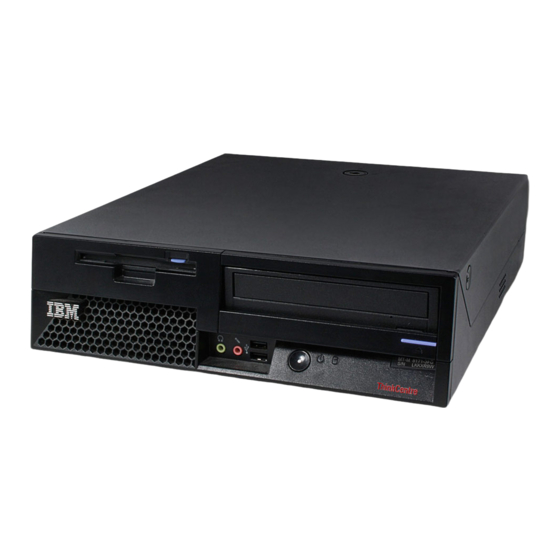
- Page 1 ™ ThinkCentre Hardware Removal and Replacement Guide Types 8424, 8425, 8428 Types 8171, 8172, 8173...
- Page 3 ™ ThinkCentre Hardware Removal and Replacement Guide Types 8424, 8425, 8428 Types 8171, 8172, 8173...
- Page 4 Second Edition (June 2004) © Copyright International Business Machines Corporation 2004. All rights reserved. US Government Users Restricted Rights – Use, duplication or disclosure restricted by GSA ADP Schedule Contract with IBM Corp.
-
Page 5: Table Of Contents
Replacing customer replaceable units (CRUs) ....1 Opening the cover © Copyright IBM Corp. 2004 Locating components Identifying parts on the system board . Removing and replacing the power supply . - Page 6 Hardware Removal and Replacement Guide...
-
Page 7: Overview
Quick Reference that was included with your computer. If you no longer have this copy of the Quick Reference, you can obtain one online from the IBM Web site at http://www.ibm.com/pc/support. Additional information resources If you have Internet access, the most up-to-date manuals for your computer are available from the World Wide Web. - Page 8 v Before you replace a new CRU, touch the static-protective package containing the CRU to a metal expansion-slot cover or other unpainted metal surface on the computer for at least two seconds. This reduces static electricity in the package and your body. v When possible, remove the new CRU from the static-protective packaging, and install it directly in the computer without setting the CRU down.
-
Page 9: Replacing Customer Replaceable Units (Crus)
Do not open your computer or attempt any repair before reading the “Safety notices” in the Quick Reference that was included with your computer. If you no longer have this copy of the Quick Reference, you can obtain one online from the IBM Web site at http://www.ibm.com/pc/support. Opening the cover Important Turn off the computer and wait 3 to 5 minutes to let the computer cool before opening the cover. -
Page 10: Locating Components
Locating components The following illustration will help you locate the various components in your computer. Diskette drive lock Memory modules Battery PCI riser Hardware Removal and Replacement Guide Power supply assembly CD or DVD drive (hard disk drive is under the CD drive) CD or DVD drive lock... -
Page 11: Identifying Parts On The System Board
Quick Reference that was included with your computer. If you no longer have this copy of the Quick Reference, you can obtain one online from the IBM Web site at http://www.ibm.com/pc/support. To remove and replace the power supply, do the following: 1. - Page 12 2. Pivot the drive bay assembly upward to gain access to the cable connections. 3. Locate the power supply. See “Locating components” on page 2. Note: Note the routing of the power supply cables. It is important to route the cables the same way when installing a new power supply assembly. 4.
- Page 13 7. Remove the screws at the rear of the chassis that secure the power supply. 8. Slide the power supply forward and remove from the computer. Replacing customer replaceable units (CRUs)
- Page 14 9. Install the new power supply into the chassis so that the screw holes in the power supply align with those in the chassis. Note: Use only the screws provided by IBM. 10. Install and tighten the four screws at the rear of the chassis that secure the power supply.
-
Page 15: Removing And Replacing The System Board Assembly
Quick Reference that was included with your computer. If you no longer have this copy of the Quick Reference, you can obtain one online from the IBM Web site at http://www.ibm.com/pc/support. To remove and replace the system board assembly, do the following: 1. - Page 16 installed. 5. Carefully note the location of all cable connections on the system board. It will be necessary to reconnect them properly after installing the new system board assembly. Note: Note the cable routing. It is important to route the cables the same way when installing a new system board.
- Page 17 15. Install the six screws to secure the system board to the chassis. Note: Use only the screws provided by IBM. 16. Reinstall the power supply. See “Removing and replacing the power supply”...
-
Page 18: Removing And Replacing The Microprocessor
Quick Reference that was included with your computer. If you no longer have this copy of the Quick Reference, you can obtain one online from the IBM Web site at http://www.ibm.com/pc/support. Important Shut down and turn off your computer for at least one hour before removing the microprocessor to allow the thermal interface between the microprocessor and the heat sink time to cool down. - Page 19 4. Release the lever 1 holding the microprocessor heat sink. 5. Remove the heat sink, and do one of the following: v If you are replacing the microprocessor, place the old heat sink aside. You must use the new heat sink shipped with the new microprocessor. Note Do not use the old heat sink with the a new microprocessor.
- Page 20 Notes: a. Notice of the orientation of the notches 1 on the microprocessor . This is important when reinstalling the microprocessor on the system board. b. Do not drop anything on the socket while it is open. Keep all contacts as clean as possible.
- Page 21 b. Remove the new microprocessor from its static-protective package. c. Hold the microprocessor 2 by its sides and loosen the black cover 3 on the microprocessor, but do not remove the black cover. d. Place the microprocessor on the static-protective package. e.
- Page 22 b. Install the microprocessor by inserting it straight down into the socket of 8. Pivot the retaining plate 1 closed, and lock the lever 3 to secure the microprocessor 2 in place. Be sure to engage the retainer tab when locking the microprocessor.
-
Page 23: Removing And Replacing Memory Modules
Quick Reference that was included with your computer. If you no longer have this copy of the Quick Reference, you can obtain one online from the IBM Web site at http://www.ibm.com/pc/support. To remove and replace the memory modules: 1. - Page 24 installed. 4. Locate the memory connectors. See “Locating components” on page 2. 5. Open the retaining clips, and lift the memory module out of its connector. 6. Insert the replacement memory module in the memory connector. Ensure the notch on the replacement memory module 1 aligns correctly with the connector key 2 on the system board.
- Page 25 7. Reinstall the PCI riser and adapters if they were removed. 8. Pivot the drive bay assembly back to the original position. 9. Close the cover and reconnect the external cables . Go to “Completing the installation” on page 19. Replacing customer replaceable units (CRUs)
-
Page 26: Removing And Replacing A Hard Disk Drive
Quick Reference that was included with your computer. If you no longer have this copy of the Quick Reference, you can obtain one online from the IBM Web site at http://www.ibm.com/pc/support. 1. Open the cover. Go to “Opening the cover” on page 1. -
Page 27: Completing The Installation
After replacing the CRUs, you need to close the cover and reconnect cables, including telephone lines and power cords. Also, depending on the CRU that was replaced, you might need to confirm the updated information in the IBM Setup Utility program. See ″Starting the IBM Set Utility″ in your Quick Reference. - Page 28 Attention Keep cables 1 through 3 clear of the hinges and sides of the computer chassis. 3. Make sure that the drive locks on the drive bay assembly are both in the locked position. Otherwise, you cannot close the cover. 4.
-
Page 29: Updating (Flashing) Bios From A Diskette
Important Start the IBM Setup Utility program to view your system information. See “Starting the IBM Setup Utility” in your Quick Reference. If the serial number and the machine type/model listed on the Main menu do not match what is printed on the label of your computer, you must update (flash) the BIOS to change the serial number and the machine type/model. - Page 30 3. When you are prompted to select a language, press the number on your keyboard which corresponds to the language then press Enter. 4. When prompted to change the serial number, press Y. 5. Type in the seven character serial number of your computer then press Enter. 6.
- Page 32 Part Number: 19R0821 Printed in USA (1P) P/N: 19R0821...