Table of Contents
Advertisement
Service Manual
MODEL
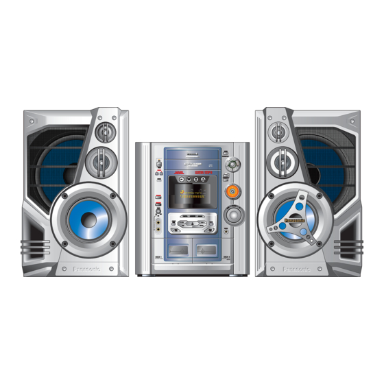
SA-HM910
SC-HM910
SB-HM910
SB-PS810
SA-HM810
SC-HM810
SB-HM810
SB-PS810
Control
SB-HM910
remoto
ESPECIFICATIONS
Front
SA-HM810
Surround
Front
SA-HM910
Surround
Subwoofer
Notes:
1. All the information are subject to change without notice.
2. Weigth and dimensions are approximate.
UNIT
Stereo
Front Speaker
Surround Speaker
Stereo
Front Speaker
SB-PS810
SB-HM910
SA-HM910
POTENCIA DE SALIDA (AMPLIFICADOR)
RMS per channel (6 Ω), 80 Hz , 10% DAT
(Low)
114 W
RMS per channel (6 Ω), 1 kHz , 10% DAT
(High)
54 W
RMS per channel (8 Ω), 1 kHz , 10% DAT
32 W
RMS per channel (6 Ω), 80 Hz , 10% DAT
(Low)
130 W
RMS per channel (6 Ω), 1 kHz , 10% DAT
(High)
70 W
RMS per channel (8 Ω), 1 kHz , 10% DAT
50 W
RMS (8 Ω), 80 Hz , 10 % DAT
100 W
SC-HM910
SC-HM810
Control
SB-HM810
SA-HM810
remoto
RQZM0167
Stereo system
SB-HM810
Advertisement
Table of Contents

Related Manuals for Panasonic SC-HM910


Summary of Contents for Panasonic SC-HM910
- Page 1 RQZM0167 Service Manual Stereo system MODEL UNIT SA-HM910 Stereo SC-HM910 SC-HM910 SB-HM910 Front Speaker SB-PS810 Surround Speaker SA-HM810 Stereo SC-HM810 SC-HM810 SB-HM810 Front Speaker SB-PS810 SB-PS810 Control Control SB-HM910 SB-HM910 SB-HM810 SB-HM810 SA-HM910 SA-HM810 remoto remoto ESPECIFICATIONS POTENCIA DE SALIDA (AMPLIFICADOR) RMS per channel (6 Ω), 80 Hz , 10% DAT...
- Page 2 SC-HM910/SC-HM810 AMPLIFIER SA-HM810 SA-HM910 Power output: 4700 W PMPO 7500 W PMPO Power consumption: 190 W 280 W Supply: 127 V ca ±10% 60 Hz Input sensitivity: 250 mV Frecuency range AM: 520 - 1710 kHz (10 kHz steps )
-
Page 3: Table Of Contents
SC-HM910/SC-HM810 WARNING This service information is designed for experienced repair technicians only and is not designed for use by the general public. It does not contain warnings or cautions to advise non-technical individuals of potential dangers in attempting to service a product. -
Page 4: Safety Precaution
Fig. 2 Before Repair and Adjustment Disconnect AC power, discharge Power Supply Capacitors POWER PCB SC-HM910 C556, C557, C558, C559, C561, POWER PCB SC-HM810 C531, C532, C533, C534 and TRANSFORMER PCB SC-HM910 C705, TRANSFORMER PCB SC-HM810 C402 through a 10 Ω, 5W resistor to ground. -
Page 5: Protection Circuitry
SC-HM910/SC-HM810 Protection Circuitry The protection circuitry may have operated if either of the following conditions are noticed. • No sound is heard when the power is turned on. • Sound stops during a performance. The function of this circuitry is to prevent circuitry damage if, for example, the positive and negative speaker connection wires are “shorted”, or if speaker systems with an impedance less than the indicated rated impedance of the amplifier are used. -
Page 6: Front Panel Controls
SC-HM910/SC-HM810 Front panel controls Unidad principal No. Nombre Pág. (AC IN) Indicador de alimentación (Este indicador se encenderá cuando el Sistema Estéreo esté conectado). , POWER ) Botón de encendido y modo de espera (En modo de espera, el Sistema Estéreo consume una pequeña cantidad de corriente eléctrica). - Page 7 SC-HM910/SC-HM810 Front panel controls Control remoto Los números que se encuentran en círculo negro como el , son funciones que se pueden operar tanto en el Sistema Estéreo como en el control remoto y se encuentran referenciados en la página 6. Los botones que están en blanco como , son funciones que se realizan sólo por medio del control remoto.
-
Page 8: Handling Precautions For Traverse Deck
SC-HM910/SC-HM810 Handling Precautions For Traverse Deck The laser diode in the traverse deck (optical pickup) may break down due to potential difference caused by static electricity of clothes or human body. So. be careful of electrostatic breakdown during repair of the traverse deck (optical pickup). -
Page 9: Operation Checks And Main Component Replacement Procedures
SC-HM910/SC-HM810 Operation Checks and Main Component Replacement Procedures “ATTENTION SERVICER” Some chassis components may have sharp edges. Be careful when disassembling and servicing. This section describes procedures for checking the operation of the major printed circuit boards and replacing the main components. - Page 10 SC-HM910/SC-HM810 7.1 Disassembly and assembly main unit Step 1 Remove 4 screws each side and 8 screws at rear panel. Step 2 Lift up both sides of cabinet ass’y, push the cabinet Step 5 Pull out the CD tray as shown and remove the CD ass’y toward the rear and remove the cabinet ass’y.
- Page 11 SC-HM910/SC-HM810 Step 7 Remove the wire CN309 and CN310 (main P.C.B.), release the 2 catches and remove the CD changer base together with the CD changer. Catch Catch CN310 CN309 Checking for Main, Panel, Deck and Power P.C.B. Step 8 Remove 4 screw.
- Page 12 SC-HM910/SC-HM810 7.4 Main Component Replacement Procedures 7.4.1. Replacement of the Traverse Deck Step 1 Follow the (step 1 ) - (step 2) of item 7.1. Catch Catch CN310 CN309 Step 5 Rotate the hexagonal wrench in the direction of arrow (clockwise), and then open the disc tray fully.
- Page 13 SC-HM910/SC-HM810 (Step 12) Step 9 Remove the traverse deck ass’y from the timing lever. Caution: Caution: Insert a short pin into the traverse When removing or inserting the traverse deck avoid touching the unit FFC board. OPU lens and pressing onto the turntable.
- Page 14 SC-HM910/SC-HM810 Note: Be careful no to lose the 3 floating spring because those will also be removed on removal of the traverse deck ass’y. • Installation of the CD Servo P.C.B. after replacement Step 1 Connect the FFC board. Step 2 Install the CD servo P.C.B. in the traverse deck ass’y.
- Page 15 SC-HM910/SC-HM810 7.5 Replacement for the disc tray • Follow the (Step 1) - (Step 2) of item 7.1 • Follow the Disassembly for the CD changer of item 7.2. • Follow the (Step 1) - (Step 8) of item 7.4.
- Page 16 SC-HM910/SC-HM810 Note: Step 9 With forcing the left guide bar manually because the Force the right guide bar of tray base manually not to move left guide bar interfers with claw, draw the disc tray. upwards. (Installation of the disc tray after replacement).
- Page 17 SC-HM910/SC-HM810 7.6 Disassembly and reassembly for mechanism base drive unit • Follow the (Step 1) - (Step 2) of item 7.1 • Follow the Disassembly for the CD changer of item 7.2. • Follow the (Step 1) - (Step 14) of item 7.4.
- Page 18 SC-HM910/SC-HM810 Step 11 Lift up the left end of spindle base unit in the direction of arrow (1), and then remove the unit in the direction of arrow (2). Step 9 Pressing the claw (B) in the direction of arrow (1), force the connection lever in the direction of arrow (2).
- Page 19 SC-HM910/SC-HM810 Step 3 Rotate the disc lever in the direction of arrow (1), draw the disc lever. Step 13 Remove the traverse relay gear, traverse cam gear and drive gear. (Dissassembly/reassembly for the spindle base unit) Step 1 Draw the 5 disc spacers.
- Page 20 SC-HM910/SC-HM810 Note: Hold the loading stopper ass’y manually because it is flipped by spring. Step 8 Release the 2 claws, and then remove the relay gear Step 9 Release the 2 claws, and then remove the spindle shaft. Step 10 Remove the lower spindle spring with tweezers.
- Page 21 SC-HM910/SC-HM810 (Installation for loading stopper ass’y) Step 1 Align the claw of loading stopper ass’y with the slot of spindle base. (Caution should be exercised when align- ment of claw due to the size of claws.) Step 2 Lower the loading stopper ass’y, and then align the lower spindle with the trapezoid tooth of relay gear A.
- Page 22 SC-HM910/SC-HM810 Step 1 Install the traverse cam gear. Step 2 Rotate the traverse cam gear to the direction of arrow. Step 4 Install the slide plate 2 to the mechanism base, and Step 3 Install the drive gear and traverse relay gear.
- Page 23 SC-HM910/SC-HM810 Step 7 Move the slide plate 1 to forward fully. Step 8 Install the rear lock. (The claw should be latched.) Step 9 Install the bottom SW P.C.B. (The claw should be latched.) Step 10 Install the tray lock. (The claw should be latched.) Step 11 Remove the tray lock spring from hook, and then latch to the tray lock.
- Page 24 SC-HM910/SC-HM810 Step 14 Install the tray base, traverse ass’y mechanism cover and upper plate. (operation check after servicing). Check the proper operation of following items with gear and hexagonal screwdriver. 1. Open/close of tray base. 2. Moving the tray base to the stock side.
- Page 25 SC-HM910/SC-HM810 1. Locate the name plate of motor to the traverse ass’y. 2. Align the hole of motor with the ribs. 7.8. Replacement for the pinch roller ass’y and head block Step 4 Pull out the FFC. • Follow the (Step 1) - (Step 2) of item 7.1.
- Page 26 SC-HM910/SC-HM810 Step 11 Remove 4 screws. Step 13 Release the 2 claws, and then remove the pinch roller Step 12 Remove mechanism Deck P.C.B. (R), (F). * The mechanism as shown below is for DECK 1. For the one of Step 14 Release ther 2 claws, and then remove the head con- DECK 2, perform the same procedures.
- Page 27 SC-HM910/SC-HM810 Step 4 Remove 2 screws. Step 2 Put the winding belt on the pulley temporarily. Step 3 Install the flywheel F. Step 4 Put the winding belt on the flywheel F. Step 5 Install the winding lever and spring while pressing the winding arm in the direction of arrow.
- Page 28 SC-HM910/SC-HM810 NOTE: The winding lever should be positioned as shown below. Step 10 Remove 3 screws. Step 7 Put the capstan belt A temporarily as shown below. Step 11 Put the capstan belt B as shown below. Step 12 Put the capstan belt A on the motor ass’y pulley.
- Page 29 SC-HM910/SC-HM810 7.10. Replacement for the CD mo- 7.11. Replacement for the cassette tor ass’y. capstan belt A, capstan lid ass’y belt B and winding belt • Follow the (Step 1) - (Step 7) of item 7.1 Step 1 Force the lever upward, open the cassette lid ass’y (For DECK 1 and DECK2).
- Page 30 SC-HM910/SC-HM810 7.12. Measure for tape trouble • Follow the (Step 1) - (Step 2) of item 7.1 Step 1 If a cassette tape cannot be removed from the deck since the tape is caught by the capstan or pich roller during playback or recording, rotate the flywheel F in the direction of the arrow to remove the tape.
-
Page 31: Precaution Of Laser Diode
SC-HM910/SC-HM810 Precaution of Laser Diode CAUTION: This unit utilizes a class 1 laser. Invisible laser radiation is emitted from the optical pickup lens. When the unit is turned on: 1.Do not look directly into the pick up lens. 2.Do not use optical instruments to look at the pick up lens. - Page 32 SC-HM910/SC-HM810 Description of Error Code 9.1. Error detection for Cassette Mechanism block Error Error Display Problem condition MODE SW Faulty operation of cassette mechanism. detection error Faulty contact or short-circuit of mechanism mode switch (S951, S971). REC INH SW Recording not possible.
-
Page 33: Self-Diagnostic Function
SC-HM910/SC-HM810 Self-Diagnostic Function 10.1. Self-diagnostic display This unit is equipped with a self-diagnostic display function which, if a problem occurs, will display an error code corresponding to the problem. Use this function when performing maintenance on the unit. 10.2. How to enter the Self-diagnostic function 10.3. -
Page 34: To Clear All Error Code
SC-HM910/SC-HM810 10.4 CD Mechanism Test (F15, F26, F16, F17, F27, F28, F29, H15) Press “CD”. Press “OPEN/CLOSE (1)” and place a CD. Press “OPEN/CLOSE (1)” to close the tray. Press “OPEN/CLOSE (5)” and wait until the tray is open. Press “OPEN/CLOSE (1)” and remove the CD. -
Page 35: Cd Test Mode Function
SC-HM910/SC-HM810 CD Test Mode Function This CD test mode is provided to check CD unit without connecting to changer loading mechanism. This mode shall operate CD PLAY with CD unit being connected only and CD Automatic Alignment result is shown on FL display. -
Page 36: Measurements And Adjustments
SC-HM910/SC-HM810 12 Measurements and Adjustments 12.1. Cassette Deck Section • Measurement Condition Make sure head, capstan and press roller are clean. Judgeable room temperature 20 ± 5°C (68 ± 9°F) • Measuring instrument EVM (DC Electronic Volmeter) Digital frecuency counter •... -
Page 37: Am Rf Adjustment
SC-HM910/SC-HM810 Set AM-SG to 520 kHz. Receive 520 kHz in the unit. Adjust Z101 (OSC) so that the EVM-DC value es with 1.1 ± 0.5V. 12.2.2. AM RF Adjustment Connect the instrument as shown in Fig. 7. Set the unit to AM mode. -
Page 38: Schematic Diagram
SC-HM910/SC-HM810 13 Schematic Diagram (All schematic diagrams may be modified at any time with the development of the new technology) Note: Push switch Push switch Switch Cd switch Lock switch S904 Power switch S602 Preset EQ switch S603 Deck 1/2 switch... - Page 39 SC-HM910/SC-HM810...
- Page 40 SC-HM910/SC-HM810...
- Page 41 SC-HM910/SC-HM810...
- Page 42 SC-HM910/SC-HM810 SCHEMATIC DIAGRAM - 4 MAIN CIRCUIT...
- Page 43 SC-HM910/SC-HM810 SCHEMATIC DIAGRAM - 5...
- Page 44 SC-HM910/SC-HM810 SCHEMATIC DIAGRAM - 6...
- Page 45 SC-HM910/SC-HM810 SCHEMATIC DIAGRAM - 7...
- Page 46 SC-HM910/SC-HM810 SCHEMATIC DIAGRAM - 8...
- Page 47 SC-HM910/SC-HM810 SCHEMATIC DIAGRAM - 9...
- Page 48 SC-HM910/SC-HM810 SCHEMATIC DIAGRAM - 10...
- Page 49 SC-HM910/SC-HM810 SCHEMATIC DIAGRAM - 11 POWER CIRCUIT (SC-HM810)
- Page 50 SC-HM910/SC-HM810 SCHEMATIC DIAGRAM - 11 POWER CIRCUIT (SC-HM910)
- Page 51 SC-HM910/SC-HM810 SCHEMATIC DIAGRAM - 12 TRANSFORMER CIRCUIT (SC-HM810)
- Page 52 SC-HM910/SC-HM810 SCHEMATIC DIAGRAM - 12 TRANSFORMER CIRCUIT (SC-HM910)
- Page 53 SC-HM910/SC-HM810 SCHEMATIC DIAGRAM - 13...
-
Page 54: Printed Circuit Board
SC-HM910/SC-HM810 14 Printed Circuit Board Note: Circuit board diagrams may be modified any time with the development of new technology. - Page 55 SC-HM910/SC-HM810...
- Page 56 SC-HM910/SC-HM810 MAIN CIRCUIT...
- Page 57 SC-HM910/SC-HM810 MAIN CIRCUIT SMT...
- Page 58 SC-HM910/SC-HM810 VOLUME & HEADPHONE MICROPHONE CIRCUIT CIRCUIT PANEL CIRCUIT REMOTE SENSOR CIRCUIT...
- Page 59 SC-HM910/SC-HM810 TACT SWITCH CIRCUIT LED DISC CIRCUIT FUNCTION CIRCUIT...
- Page 60 SC-HM910/SC-HM810...
- Page 61 SC-HM910/SC-HM810 POWER CIRCUIT (SC-HM910)
- Page 62 SC-HM910/SC-HM810 POWER CIRCUIT (SC-HM810)
- Page 63 SC-HM910/SC-HM810 TRANSFORMER CIRCUIT (SC-HM910) F1 T4.0A...
- Page 64 SC-HM910/SC-HM810 TRANSFORMER CIRCUIT (SC-HM810) F1 T4.0A...
- Page 65 SC-HM910/SC-HM810...
-
Page 66: Block Diagram
SC-HM910/SC-HM810 15 Block Diagram... - Page 67 SC-HM910/SC-HM810...
- Page 68 SC-HM910/SC-HM810...
- Page 69 SC-HM910/SC-HM810...
- Page 70 SC-HM910/SC-HM810...
- Page 71 SC-HM910/SC-HM810...
- Page 72 SC-HM910/SC-HM810 SC-HM910...
- Page 73 SC-HM910/SC-HM810 SC-HM810...
-
Page 74: Wiring Connection Diagram
1 ..19 12 ..1 6 . . . 1 1 . . .6 CP600 CP602 CP900 CP601 H920A/W920 BAFFLES SURROUND *SUBWOOFER *SOLO SC-HM910 FM ANT AM ANT JK500 JK501 JK101 JK502 JK300 Z101 CP501 CN300... -
Page 75: Illustration Of Ic, Transistors And Diodes
SC-HM910/SC-HM810 17 Illustration of IC’s Transistors and Diodes... - Page 76 SC-HM910/SC-HM810...
- Page 77 SC-HM910/SC-HM810...
- Page 78 SC-HM910/SC-HM810...
-
Page 79: Troubleshooting Guide
SC-HM910/SC-HM810 19 Troubleshooting Guide... -
Page 80: Parts Location And Replacement Parts List
SC-HM910/SC-HM810 20 Part Location and Replacement Part List NOTES: • Important safety notice: Components identified by this mark have special characteristics important for safety. Furthermore, special parts which have purposes of fire-retardent (resistors), high-quality sound (capacitors), low noise (resistors), etc are used. - Page 81 SC-HM910/SC-HM810 20.1 Deck Mechanism 20.1.1. Deck Mechanism Parts Location...
- Page 82 SC-HM910/SC-HM810...
-
Page 83: Deck Mechanism Parts List
SC-HM910/SC-HM810 20.1.2. Deck Mechanism Parts List Ref. No. Part No. Part Name & Description Remarks CASSETTE DECK RED0064-1 R/P HEAD BLOCK UNIT RED0063-1 R/B HEAD BLOCK UNIT RDG0300 REEL BASE GEAR RDG0301 WINDING RELAY GEAR RDK0026-4 MAIN GEAR RDR0029-4 RELAY PULLEY... - Page 84 SC-HM910/SC-HM810...
- Page 85 SC-HM910/SC-HM810...
- Page 86 SC-HM910/SC-HM810...
-
Page 87: Cabinet Parts Location
SC-HM910/SC-HM810 20.3 Cabinet 20.3.1. Cabinet Parts Location PANEL P.C.B. DECK P.C.B. CN1001 CS1001 CS1002 CS951 CS971... - Page 88 SC-HM910/SC-HM810 BACKUP TRANSFORMER W500A T502 JK500 JK500 JK501 CN502 JK502 CN501 E500 CP501 POWER W500B P.C.B. T501 CP500 W500 /H500 TRANSFORMER P.C.B TUNER PACK JK101 Z120 CN302 JK300 MAIN CN303 P.C.B. CN300 CN304 CN301 * ONLY SC-HM910...
-
Page 89: Cabinet Parts List
SC-HM910/SC-HM810 20.3.2. Cabinet Parts List CASSETTE DECK RSC0027-3 TUNER PACK REEM0085 WIRE 17 PIN RMNX0073 PCB SUPPORT REEM0088 WIRE 10 PIN RXXM0019 HEAT SINK UNIT REEM0086 WIRE 30 PIN RMKX0063 CD CHASSIS RGWX0042-4S1 MIC-KNOB RD-DAC024-PX CD MECHANISM RYPM0123 PANEL FRONTAL HM910... -
Page 90: Electrical Parts List
SC-HM910/SC-HM810 20.4. Electrical Parts List * ONLY SC-HM810 ** ONLY SC-HM910 Ref. No. Part No. Part Name & Description Marks Ref. No. Part No. Part Name & Description Marks P.C.B. WITH COMPONENTS SC-HM810 C1020 ECJ1VB1H471K CAPACITOR C1021 ECJ1VB1H471K CAPACITOR RAIM033104P... - Page 91 SC-HM910/SC-HM810 Ref. No. Part No. Part Name & Description Remarks Ref. No. Part No. Part Name & Description Remarks C126 ECUV1C105ZFN CAPACITOR C302 ECJ1VB1E103K CAPACITOR C127 ECEA1CKA220B CAPACITOR C303 F1H1H102A761 CAPACITOR C129 ECEA0JKA101B CAPACITOR C304 ECEA1HKA010B CAPACITOR C130 ECEA0JKA101B CAPACITOR...
- Page 92 SC-HM910/SC-HM810 Ref. No. Part No. Part Name & Description Remarks Ref. No. Part No. Part Name & Description Remarks C369 ECJ1VC1H560J CAPACITOR C424 ECEA1HKA010B CAPACITOR C370 ECJ1VB1E103K CAPACITOR C425 ECJ1VC1H101K CAPACITOR C371 ECJ1VB1C103K CAPACITOR C426 ECJ1VC1H470J CAPACITOR C372 ECA1CM221B CAPACITOR...
- Page 93 SC-HM910/SC-HM810 Ref. No. Part No. Part Name & Description Remarks Ref. No. Part No. Part Name & Description Remarks C531 ECA1VM332E CAPACITOR C641 F1H1C683A075 CAPACITOR MAIN C532 ECKR2H103ZF5 CAPACITOR C641 ECEA1VKA220B CAPACITOR PANEL C532 ECA1VM562E CAPACITOR C642 ECBT1H471KB5 CAPACITOR POWER...
- Page 94 SC-HM910/SC-HM810 Ref. No. Part No. Part Name & Description Remarks Ref. No. Part No. Part Name & Description Remarks C679 ECEA1CKA100B CAPACITOR C983 ECEA1HKA4R7B CAPACITOR MAIN C680 ECEA1CKA100B CAPACITOR C983 ECBT1H104ZF5 CAPACITOR PANEL ECBT1H4R7KC5 CAPACITOR C984 ECEA1HKA4R7B CAPACITOR MAIN C700...
- Page 95 SC-HM910/SC-HM810 Ref. No. Part No. Part Name & Description Remarks Ref. No. Part No. Part Name & Description Remarks D309 B0AAMM000009 DIODE D530 B0JAPG000019 DIODE D310 B0ACCK000005 DIODE D531 B0JAPG000019 DIODE D312 1SS380TE-17 DIODE D555 RL1N4003S-P DIODE D313 1SS380TE-17 DIODE...
- Page 96 SC-HM910/SC-HM810 Ref. No. Part No. Part Name & Description Remarks Ref. No. Part No. Part Name & Description Remarks H601 RMR0315 HOLDER L603 RLQZP101KT-Y COIL H605 RMR0312 HOLDER L604 RLQZP100KT-Y COIL H920 RMR0315 HOLDER L605 RLQZP100KT-Y COIL H921A RMR0314 HOLDER...
- Page 97 SC-HM910/SC-HM810 Ref. No. Part No. Part Name & Description Remarks Ref. No. Part No. Part Name & Description Remarks Q371 2SD0592ARA TRANSISTOR Q975 KRA102STA TRANSISTOR Q372 B1ADCF000001 TRANSISTOR Q976 KRC102STA TRANSISTOR Q373 2SD0592ARA TRANSISTOR Q977 KTD1304TA TRANSISTOR Q374 B1ADCF000001 TRANSISTOR...
- Page 98 SC-HM910/SC-HM810 Ref. No. Part No. Part Name & Description Remarks Ref. No. Part No. Part Name & Description Remarks R1061 ERJ3GEY0R00V RESISTOR R207 ERJ3GEYJ330V RESISTOR R107 D0GB331JA002 RESISTOR R208 D0GB332JA002 RESISTOR R1084 ERJ3GEYJ222V RESISTOR R209 ERJ3GEYJ561V RESISTOR R1085 ERJ3GEYJ473V RESISTOR...
- Page 99 SC-HM910/SC-HM810 Ref. No. Part No. Part Name & Description Remarks Ref. No. Part No. Part Name & Description Remarks R318 ERJ3GEY0R00V RESISTOR R384 ERJ3GEYJ103V RESISTOR R320 D0GB101JA002 RESISTOR R385 ERJ3GEYJ103V RESISTOR R321 D0GB101JA002 RESISTOR R386 ERJ3GEYJ103V RESISTOR R322 D0GB101JA002 RESISTOR...
- Page 100 SC-HM910/SC-HM810 Ref. No. Part No. Part Name & Description Remarks Ref. No. Part No. Part Name & Description Remarks R433 ERJ3GEYJ472V RESISTOR R526 ERDS2TJ2R2T RESISTOR R434 ERJ3GEYJ104V RESISTOR R526 ERDS2TJ103T RESISTOR R435 D0GB152JA002 RESISTOR R527 ERDS2TJ104T RESISTOR R436 D0GB183JA002 RESISTOR...
- Page 101 SC-HM910/SC-HM810 Ref. No. Part No. Part Name & Description Remarks Ref. No. Part No. Part Name & Description Remarks R601 ERDS2TJ102T RESISTOR R650 ERDS2TJ471T RESISTOR R602 ERDS2TJ154T RESISTOR R651 ERDS2TJ471T RESISTOR R602 ERDS2TJ102T RESISTOR R652 ERDS2TJ471T RESISTOR R603 ERDS2TJ684T RESISTOR...
- Page 102 SC-HM910/SC-HM810 Ref. No. Part No. Part Name & Description Remarks Ref. No. Part No. Part Name & Description Remarks R832 ERJ3GEY0R00V RESISTOR R902 ERDS2TJ102T RESISTOR R833 ERJ3GEY0R00V RESISTOR R903 ERDS2TJ122T RESISTOR R834 ERJ3GEYJ472V RESISTOR R904 ERDS2TJ182T RESISTOR R835 ERJ3GEY0R00V RESISTOR...
- Page 103 SC-HM910/SC-HM810 Ref. No. Part No. Part Name & Description Remarks Ref. No. Part No. Part Name & Description Remarks R981 ERDS2TJ102T RESISTOR PANEL S908 EVQ21405R TACT SWITCH R982 D0GB332JA002 RESISTOR MAIN S909 EVQ21405R TACT SWITCH R982 ERDS2TJ102T RESISTOR PANEL S910...
-
Page 104: Speaker Parts List
XTB4+8JFZ SCREW REVM0056-1 WIRE RYPM0085 FRONT PANEL (R ) RMRM0014 WIRE CATCHER RYPM0086 FRONT PANEL (L) RKPM0070 WOOD CAB. (R) SC-HM910 REVM0090 WIRE RKPM0072 WOOD CAB. (R) SC-HM810 XTB3+10G-A SCREW RKPM0071 WOOD CAB. (L) SC-HM910 EAS17PL302M SPEAKER SC-HM910 RKPM0073 WOOD CAB. (L) SC-HM810...