Table of Contents
Advertisement
SC-HTB488_688_EGEBGN_TQBJ2019.book 1 ページ 2016年12月2日 金曜日 午後5時57分
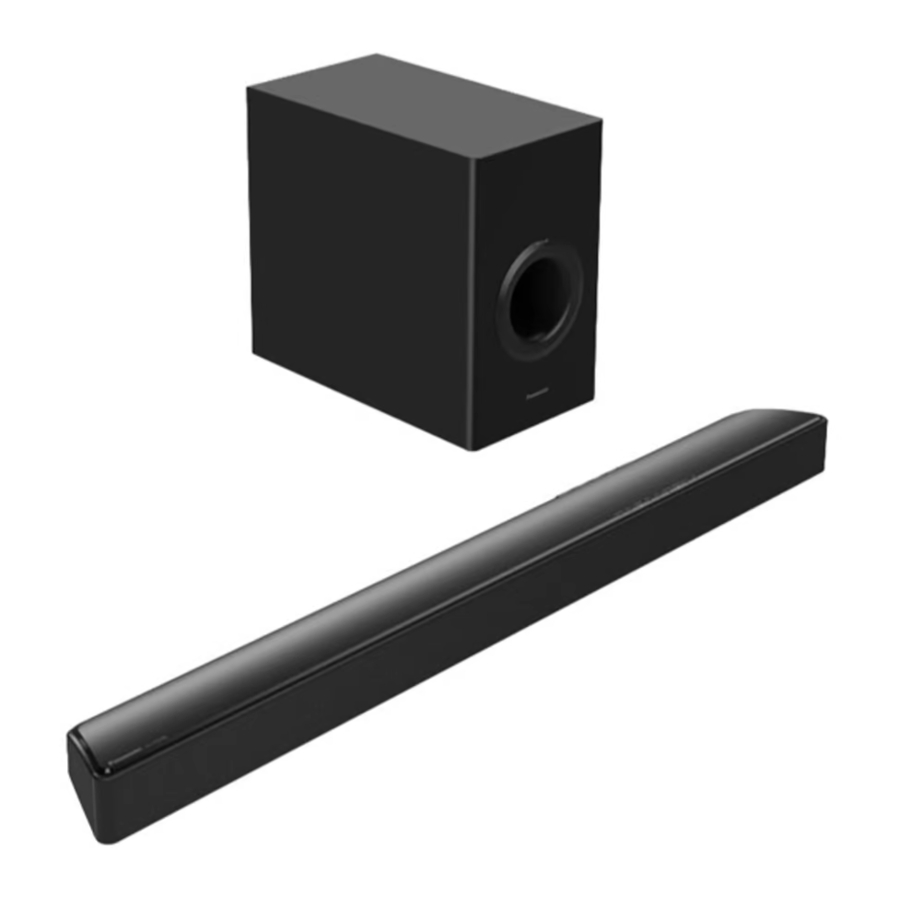
Home Theater Audio System
Remote
Control
Thank you for purchasing this product.
Please read these instructions carefully before using this product,
and save this manual for future use.
Included Installation Instructions
The installation work should be done by a qualified installation specialist. ( 12 to 17)
Before commencing work, carefully read these installation instructions and the operating instructions
to ensure that installation is performed correctly.
(Please keep these instructions. You may need them when maintaining or moving this system.)
Model number suffix "EB" denotes UK model.
EG EB GN
2017/01/04
This service information is designed for experienced repair technicians only and is not designed for use by the general
public. It does not contain warnings or cautions to advise non-technical individuals of potential dangers in attempting
to service a product. Products powered by electricity should be serviced or repaired only by experienced professional
technicians. Any attempt to service or repair the product or products dealt with in this service information by anyone else
could result in serious injury or death.
Operating Instructions
Model No. SC-HTB688
SU-HTB488
SU-HTB494
SU-HTB498
Home Theater Audio System
Model No.
SC-HTB498
SC-HTB488
SB-HWA488
Colour:(K)...........Black Type
TQBJ2019
WARNING
© Panasonic Corporation 2017
Unauthorized copying and distribution is a violation of law.
ORDER NO.PSG1701012CE
SC-HTB488EB
SC-HTB488EG
SC-HTB494EG
SC-HTB498EB
SU-HTB488EB
SU-HTB488EG
SU-HTB494EG
SU-HTB498EB
SB-HWA488EB
SB-HWA488EG
Advertisement
Table of Contents

Related Manuals for Panasonic SC-HTB488EB


Summary of Contents for Panasonic SC-HTB488EB
- Page 1 Any attempt to service or repair the product or products dealt with in this service information by anyone else could result in serious injury or death. © Panasonic Corporation 2017 Unauthorized copying and distribution is a violation of law.
-
Page 2: Table Of Contents
TABLE OF CONTENTS PAGE 1 Safety Precautions ----------------------------------------------- 3 1.1. General Guidelines ----------------------------------------- 3 1.2. Leakage Current Cold Check ----------------------------- 3 1.3. Leakage Current Hot Check (See Figure 1.) --------- 3 1.4. Protection Circuitry------------------------------------------- 3 2 Warning -------------------------------------------------------------- 4 2.1. Prevention of Electrostatic Discharge (ESD) to Electrostatically Sensitive (ES) Devices ------------ 4 2.2. -
Page 3: Safety Precautions
1 Safety Precautions 1.1. General Guidelines 1. IMPORTANT SAFETY NOTICE There are special components used in this equipment which are important for safety. These parts are marked by the Schematic Diagrams, Circuit Board Layout, Exploded Views and Replacement Parts List. It is essential that these critical parts should be replaced with manufacturer’s specified parts to prevent X-RADIATION, shock, fire, or other hazards. -
Page 4: Warning
2 Warning 2.1. Prevention of Electrostatic Discharge (ESD) to Electrostatically Sensitive (ES) Devices Some semiconductor (solid state) devices can be damaged easily by static electricity. Such components commonly are called Electrostatically Sensitive (ES) Devices. Examples of typical ES devices are IC(integrated circuits)and some field-effect transistors and semiconductor “chip”... -
Page 5: Caution For Ac Cord (For Eb)
1. Remove the Fuse Cover with a screwdriver. A replacement fuse cover can be purchased from your local Panasonic Dealer. If the fitted moulded plug is unsuitable for the socket outlet in your home then the fuse should be removed and the plug cut off and disposed of safety. -
Page 6: Service Caution Based On Legal Restrictions
2.3. Service Caution Based on Legal Restrictions 2.3.1 General Description About Lead Free Solder (PbF) The lead free solder has been used in the mounting process of all electrical components on the printed circuit boards used for thisequipment in considering the globally environmental conservation. The normal solder is the alloy of tin (Sn) and lead (Pb). -
Page 7: Service Navigation
3 Service Navigation 3.1. Service Information This service manual contains technical information, which allow service personnels to understand and service this model. Please place orders with the numbers in the parts list and not the numbers in the exploded views. If the circuit is changed or modified, the information will be followed by service manual to be controlled with original service manual. -
Page 8: Speci Ications
4 Specifications AMPLIFIER SECTION GENERAL Power consumption RMS output power: Dolby Digital Mode HTB498 Main unit 19 W Front ch (L, R ch) Active subwoofer 45 W per channel (6 Ω),1 kHz,10%, THD 18 W Subwoofer ch In standby condition 90 W per channel (3 Ω),100 Hz,10%, THD Main unit ®... - Page 9 SPEAKER SECTION Front speakers (Built-in) Full range 4.5x12 cm (cone type) x 1/ch Active subwoofer Woofer 16cm cone type x 1 WIRELESS SECTION Wireless module Frequency Range 2.404 GHz to 2.478 GHz Maximum RF Power - 0.09dBm No. of channels ®...
-
Page 10: Location Of Controls And Components
5 Location of Controls and Components Control reference guide This system (Front) - Page 11 This system (Rear)
- Page 12 Remote control SUBWOOFER ...
-
Page 13: Service Mode
Service Mode This unit has Service Mode function that can resave the operation record of unit keys or the remote controller from the flash memory to USB stick for service personnel confirmation use. This unit has Service Mode function that can resave the operation record of unit keys or the remote Steps controller from the flash memory to USB stick for service personnel confirmation use. - Page 14 How to read the Operation Record • Last 200 times operations are recorded.(May more or less due to different status. This chapter describes the case based on the 200 times.) • Before delivery all records show as FF. (When performing factory delivery settings, the record will be all restored as FF.) •...
-
Page 15: Troubleshooting Guide
7 Troubleshooting Guide No power No power Main Unit (SU-HTB488/494/498) 7.1.1 No power Press the Power Check the cable is connected Check output at 25.4V Change button on the unit to LED no light up. correctly (Main XP417 to Power [Refer to check point ①] Main PCB Unit Press the Power... - Page 16 “No Sound (Bluetooth®)” LED PCB Unit No Key Function 7.1.4. No Key Function Check the cable is 3.3 V Check the FFC cable is connect correct Connect the AC at “STB_3V3” connect correct (Main Change KEY PCB (LED&BT XP2 to KEY mains lead [Refer to check point ③] XP9 to LED XP1)
- Page 17 3 3 V 3.3 V Connect the AC Change at “STB_3V3” mains lead Main PCB Unit [Refer to check point ④] 7.1.7. No Sound 7.1.7.1. No Sound (Bluetooth®) No Sound (Bluetooth®) If the pairing failure, Go to “Bluetooth® Pairing failure” No HDMI OUT Press the Power 3.3 V...
- Page 18 7.1.8. Check Points POWER P.C.B. 25.4V MAIN P.C.B. STB_3V3 SYS_5V...
- Page 19 MAIN P.C.B. STB_3V3...
-
Page 20: Active Subwoofer (Sb-Hwa488)
No power Active Subwoofer (SB-HWA488) Check the cable is Check output at Check the cable is Change 3.3V At “STB_3V3” connected correctly 25.4V connected correctly Subwoofer 7.2.1 Connect the AC No power LED no light [Refer to check (Main XP5 to LED [Refer to check (Main XP4 to Power Box Unit... - Page 21 MAIN P.C.B. STB_3V3...
-
Page 22: Wiring Connection And Voltage Data
8 Wiring Connection and Voltage Data Main Unit (SU-HTB488/494/498) SUB OUT SUB OUT WIRELESS OPT IN HDMI IA3S4 PCM1808 MAIN P.C.B. F4558 F4558 74LVC2G04 74LVC2G04 DC-DC TLV62565 AUDIO PROCESSOR MT8301 TAS5342A TAS5342A TAS5534 TAS5534 DC-DC DC-DC TPS562200 TPS562200 DC-DC SY8292 FLASH SDRAM XTAL... - Page 23 VOLTAGE DATA (measurement status:Power On and No any external signal input ) PIN NO. VALUE PIN NO. VALUE XP413 3.3V 0.78V CN207 3.3V 0.78V PIN NO. VALUE XP414 0.78V XP114 0.78V 1.6V PIN NO. VALUE 1.6V CON1 1.6V PIN NO. VALUE 3.3V 3.3V...
-
Page 24: Active Subwoofer (Sb-Hwa488)
Active Subwoofer (SB-HWA488) POWER P.C.B. MAIN P.C.B. MAIN P.C.B. DC-DC TPS562200 LED P.C.B. TDA7492E TDA7492E ES7144 WIRELESS IA3S4 IA3S4 SUB IN... - Page 25 VOLTAGE DATA (measurement status:Power On and No any external signal input ) PIN NO. VALUE 9.6V 9.6V PIN NO. VALUE 2.8V 0.1V PIN NO. VALUE 25.4V 25.4V 25.4V 3.3V...
-
Page 26: Service Fixture & Tools
9 Service Fixture & tools For better servicing purpose,prepare service tool. Service tool Part no Main P.C.B.-LED P.C.B. TNMX064... -
Page 27: Disassembly And Assembly Instructions
10 Disassembly and Assembly Instructions 10.1. Disassembly Flow Chart The following chart is the procedure of disassembling the casing and inside parts for internal inspection when carrying out the servicing. To assemble the unit, reverse the steps shown in the chart below. 10.1.1 Main Unit (SU-HTB488/494/498) 1.Front Cabinet Unit 2.AC Cord... -
Page 28: Positions
10.2. P.C.B. Positions 10.2.1 Main Unit (SU-HTB488/494/498) Power P.C.B. Main P.C.B. Key P.C.B. Speaker 1 Speaker Bluetooth Antenna P.C.B. LED P.C.B. Wireless Antenna P.C.B. 10.2.2 Active Subwoofer (SB-HWA488) Woofer Speaker LED P.C.B. Power P.C.B. Main P.C.B. -
Page 29: Disassembly Procedure Of Main Unit (Su-Htb488/494/498)
10.3. Disassembly Procedure of Main Unit (SU-HTB488/494/498) 10.3.1. Front Cabinet Unit 1. Remove 8 Black Screws (A). 2. Lift up Main Unit. 3. Pull the Front Cabinet Unit in the direction of your side. Black Screw (A) Black Screw (A) Front Cabinet Unit... - Page 30 10.3.2. AC Cord 1. Disconnect connector (A),(B). 2. Pull up the AC Cord from the AC Cord Bracket in the direction of arrow. 3. Pull the AC Cord out from the rear side of the Back Cabinet Unit. Back Cabinet Unit Connector(B) AC Cord AC Cord Bracket...
- Page 31 10.3.4. Main P.C.B. Unit (Main P.C.B.+ Wireless Antenna P.C.B.) 1. Remove 2 Black Screws (C). 2. Disconnect FFC cable. 3. Disconnect connector (A),(B),(C). 4. Remove the Main P.C.B.. 5. Pull out the Wireless Antenna P.C.B. by thin screw driver in the direction of arrow. Caution: Before the installment completely wipe off the double sticky tape left on the front cabinet unit, otherwise the Antenna sensitivity will be effected.Moreover when installing press the Wireless Antenna P.C.B.
- Page 32 10.3.6. Speaker 1. Disconnect 2 Speaker Cable Terminals. 2. Remove 4 Black Screws (A). 3. Remove the Speaker 1. (Remove Speaker 2 in the same way.) Black Screw (A) Black Screw (A) Speaker 2 Speaker Cable Terminal(+) Speaker 1 Speaker Cable Terminal(-) 10.3.7.
-
Page 33: Disassembly Procedure Of Of Active Subwoofer (Sb-Hwa488)
10.4. Disassembly Procedure of Active Subwoofer (SB-HWA488) 10.4.1. Back Panel Unit (Back Panel+AC 10.4.2. Main P.C.B. Cord) 1. Remove 4 Silver Screws (A). 2. Disconnect connector (A). 1. Remove 6 Black Screws (A). 3. Remove the Main P.C.B. . Main P.C.B. Connector(A) Silver Silver... - Page 34 10.4.3. Power P.C.B 10.4.4. Woofer Speaker 1. Disconnect connector (A). 1. Remove 4 Black Screws (A). 2. Remove 4 Silver Screws (A). 2. Remove the Woofer Speaker Cover. 3. Remove the Power P.C.B. . 3. Pull the Woofer Speaker in the direction of your side. 4.Disconnect 2 Speaker Cable Terminals.
-
Page 35: Measurements And Adjustments
Measurements and Adjustments 11.1. Service Position MAIN P.C.B. TNMX064 LED P.C.B.