
Related Manuals for Icom IC-FR5000 Series


Summary of Contents for Icom IC-FR5000 Series
- Page 1 Version 1.0 May 2008 IC IC- - FR5000/FR6000 Series FR5000/FR6000 Series Sales Handbook Sales Handbook...
- Page 2 Handbook Revisions Handbook Revisions Handbook Revisions Handbook Revisions Icom reserves the right to make changes to the content of this handbook at any time without notice or obligation. IPR and Copyrights IPR and Copyrights IPR and Copyrights...
-
Page 3: Table Of Contents
Table of Contents Table of Contents 1 Introduction Company Profile · · · · · · · · · · · · · · · · · · · · · · · · · · · · · · · · · · · · · · · · · · · · · · · · · · · · · · · · · · 2 Overview Product Line Up ·... -
Page 4: Introduction
Icom, the wireless communication experts Icom, the wireless communication experts Icom Inc. is a company located in Osaka, Japan, and is a manufacturer of wireless communication products. Since Icom’s establishment in 1954, we have had a long record as a trusted manufacturer of land mobile radio, amateur radio, marine radio, navigation products, aviation radio and communications receivers. -
Page 5: Overview Product Line Up
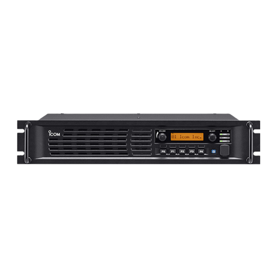
Overview Product Line Up VHF FM Repeater VHF FM Repeater VHF FM Repeater VHF FM Repeater UHF FM Repeater UHF FM Repeater UHF FM Repeater UHF FM Repeater Supplied Accessories Dimensions 409 (16 DC Power Cable (OPC-1784) ………… 1 MP1 3063 Handle ………………………………… 2 483 (19 MP2 3063 H-Spacer ………………………………... -
Page 6: Common Features
“IDAS” 6.25KHZ DIGITAL CAPABLE REPEATERS “IDAS” 6.25KHZ DIGITAL CAPABLE REPEATERS The IC-FR5000/FR6000 series is the first Icom “IDAS” 6.25kHz digital capable repeater, in addition to the IC-F3160, F5060 series radios. The “IDAS” system increases existing 12.5kHz channel capacity and offers easy migration from analog to digital. - Page 7 The IC-FR5000 series has a D-SUB 25-pin accessory inch rack mount, 2U height low profile design inch rack mount, 2U height low profile design The IC-FR5000 series has a rack mount bracket and connector for connecting LTR™/PassPort™ trunking* handles for installation in an industry standard 19-inch controllers or other external devices.
-
Page 8: 6.25 Khz Fdma Technology
6.25 kHz bandwidth. To take advantage of with existing analog FM hardware. this opportunity, Icom and Kenwood entered into a joint Instead, 4LFSK modulation was selected using FDMA agreement to develop 6.25 kHz technology. This for transmission. - Page 9 A frequency coordinator will Audio quality over distance is also greatly improved with coordinate channels for minimum adjacent channel Icom’s 6.25 kHz technology. Instead of the early interference. degradation of audio that you see in an analog signal, the 6.25 kHz digital audio quality remains higher over a...
- Page 10 The figure on the left is the emission mask for a 6.25 kHz channel. The Icom 6.25kHz FDMA signal clearly operates within the mask. Accordingly, the FCC certified the F3061/4061 as the first ever 6.25 kHz radio.
- Page 11 6.25 kHz FDMA Technology U U U U HF Considerations* HF Considerations* HF Considerations* HF Considerations* Split a 25 kHz or 12.5 kHz Channel Split a 25 kHz or 12.5 kHz Channel Split a 25 kHz or 12.5 kHz Channel Split a 25 kHz or 12.5 kHz Channel Both 2-for-1 and 4-for-1 efficiencies may be realized by A number of frequency allocation options for 6.25 kHz...
- Page 12 VHF Considerations* The VHF narrowband plan is 7.5 kHz channels, which has eliminated the geographical separation requirement. Tests have proven the Icom 6.25 kHz signal can be used within a 7.5 kHz channel with no interference to the adjacent channel.
-
Page 13: Function And Specifications Vhf Fm Repeaters
Function and Specifications 2-4-1 VHF FM Repeaters Model No. IC-FR5000 IC-FR5000 Version Destinations USA-01 EXP-01 Type Approval Local T/A Function Comparison CTCSS ✔ ✔ DTCS ✔ ✔ 2-Tone 5-Tone ✔ ✔ DTMF Autodial ✔ ✔ DTMF Decoder ✔ ✔ BIIS 1200 MDC 1200 6.25kHz digital ✔... -
Page 14: Uhf Fm Repeaters
2-4-2 UHF FM Repeaters Model No. IC-FR6000 IC-FR6000 IC-FR6000 IC-FR6000 Version Destinations USA-01 USA-02 EXP-01 EXP-02 Type Approval Local T/A Local T/A Function Comparison CTCSS ✔ ✔ ✔ ✔ DTCS ✔ ✔ ✔ ✔ 2-Tone 5-Tone ✔ ✔ ✔ ✔ DTMF Autodial ✔... -
Page 15: Optional Accessories
Optional Accessories * Some optional accessories are not available in some countries. EXTERNAL SPEAKERS EXTERNAL SPEAKERS EXTERNAL SPEAKERS EXTERNAL SPEAKERS SP- - - - 5 5 5 5 : Large external SP- - - - 10 10 : Mid sized SP- - - - 22 22 : Compact and easy- speaker. -
Page 16: Installation And Connection
Installation and Connections Installation and Connections Installation and Connections Installation and Connections 3-1-1 Unpacking Unpacking Unpacking Unpacking Front panel connections Front panel connections Front panel connections Front panel connections After unpacking, immediately report any damage to the delivering carrier or dealer. Keep the shipping cartons. For a description and a diagram of accessory equipment included with the IC-FR5000/FR6000 series, see ‘Supplied accessories’... -
Page 17: Installation And Connection
Installation and Connections Rear panel connections Rear panel connections Rear panel connections Rear panel connections Power supply connection Power supply connection Power supply connection Power supply connection Make sure the repeater’s power is turned OFF when connecting a DC power cable. ▒... -
Page 18: Ur-Fr5000/Ur-Fr6000 Installation
3-1-2 UR-FR5000/UR-FR6000 Installation UR- - - - FR5000/UR FR5000/UR FR5000/UR- - - - FR6000 CHANNEL EXTENSION FR5000/UR FR6000 CHANNEL EXTENSION FR6000 CHANNEL EXTENSION FR6000 CHANNEL EXTENSION 3 Disconnect the control cable from the channel MODULES MODULES MODULES MODULES module (original), then remove the front panel. SUPPLIED ACCESSORIES SUPPLIED ACCESSORIES SUPPLIED ACCESSORIES... - Page 19 UR-FR5000/UR-FR6000 Installation INSTALLATION INSTALLATION INSTALLATION INSTALLATION ASSEMBLE THE UNIT ASSEMBLE THE UNIT ASSEMBLE THE UNIT ASSEMBLE THE UNIT • Install the UR • Install the UR • Install the UR • Install the UR- - - - FR5000 or UR FR5000 or UR FR5000 or UR- - - - FR6000(channel FR5000 or UR...
-
Page 20: Operation And Function
Operation and Function Panel Description Note: Operation of the functions described below may depend on repeater programming. ❶ INTERNAL SPEAKER INTERNAL SPEAKER ❼ MICROPHONE/SPEAKER CONNECTOR [MIC/SP] MICROPHONE/SPEAKER CONNECTOR [MIC/SP] INTERNAL SPEAKER INTERNAL SPEAKER MICROPHONE/SPEAKER CONNECTOR [MIC/SP] MICROPHONE/SPEAKER CONNECTOR [MIC/SP] Monitors received signals. This 8-pin modular jack accepts the optional microphone. -
Page 21: Panel Description
Panel Description Function display Function display Function display Function display ❹ COMPANDER INDICATOR COMPANDER INDICATOR COMPANDER INDICATOR COMPANDER INDICATOR ❶ SIGNAL STRENGTH INDICATOR SIGNAL STRENGTH INDICATOR SIGNAL STRENGTH INDICATOR SIGNAL STRENGTH INDICATOR Appears when the compander function is activated. Indicates relative signal strength level. ❺... -
Page 22: Functions Programmable To Assignable Keys
4-1-1 Functions Programmable to Assignable Keys Key Assign Key Assign Key Assign Key Assign • Null Null Null Null Assign a function to each programmable key; No function. [Dial]/[P0]/[P1]/[P2]/[P3] and [P4]. [Dial]/[P0]/[P1]/[P2]/[P3] P4]. [Dial]/[P0]/[P1]/[P2]/[P3] [Dial]/[P0]/[P1]/[P2]/[P3] P4]. P4]. The functions you can assign to [DIAL] are limited. •... - Page 23 OPT1/2/3 Out OPT1/2/3 Out OPT1/2/3 Out ON and OFF. This key's function is exclusive for use with non-Icom When this function is assigned to any programmable units. When [OPT 1/2/3 Out] is selected, active level key, the key lock function is turned "ON" when 1min.
-
Page 24: Display Assign
4-1-2 Display Assign Text setting for Opening Text and Label Text setting for Opening Text and Label Display Display Text setting for Opening Text and Label Text setting for Opening Text and Label Display Display • Opening Text Opening Text Opening Text Opening Text Enter up to a 12-character repeater opening message... -
Page 25: Connector Description
4-1-3 Connector Description Accessory connector Accessory connector Accessory connector Accessory connector Pin No. Pin Name Description Specification No connection — — Output terminal for serial communication data. — Input terminal for serial communication data. — Output terminal for request-to-send data. Input terminal for clear-to-send data. - Page 26 Connector Description Port Setting : Port Setting : Port Setting : Port Setting : Function Function Function Function- - - - When "Output" is selected in In/Out When "Output" is selected in In/Out When "Output" is selected in In/Out When "Output" is selected in In/Out Assign a function to each port;...
-
Page 27: Cloning Software Cs-Fr5000 Basic Setup Of Cloning Software
“Add or Remove Programs.” “306401-000001” as the ID number. Then, select the program group ‘Icom CS-FR5000’ and click [Remove]. Note 1: Icom distributes cloning software by CD or license. Depending on this, some information here may not apply as written, e.g. ID number. -
Page 28: Basic Setup Of Cloning Software
Basic Setup of Cloning Software Connections Connections Connections Connections ▒ All cloning operations are performed from the computer’s mouse or keyboard— the operation required on the ▒ receiver side is; ▒ 1 First, connect the cloning cable as illustrated below. ▒... -
Page 29: Cloning Items
4-2-2 Cloning Items Cloning items Cloning items Cloning items Cloning items Common Setting Common Setting Common Setting Common Setting SCAN SCAN SCAN SCAN Key & Display Key & Display Key & Display Key & Display Scan List Scan List Scan List Scan List Assign one of several functions to the Dealer A total of 17 scanning lists are available for a wide... -
Page 30: Operation
Operation Receiving and transmitting Receiving and transmitting Receiving and transmitting Receiving and transmitting Base station operation Base station operation Base station operation Base station operation Repeater operation Repeater operation Repeater operation Repeater operation Receiving Receiving Receiving Receiving Ask your dealer for details of the repeater’s ①... -
Page 31: Multiple Table
Multiple Table Multiple table function Multiple table function Multiple table function Multiple table function • Decode/Encode Decode/Encode Decode/Encode Decode/Encode Enter the desired C. Tone and/or RAN code for Decode The IC-FR5000/FR6000 allows relaying between and Encode columns respectively. multiple groups with one repeater. (When group separation is carried out with a continuous tone) ▒... -
Page 32: Remote Control Function
When starting the Hyper Terminal software the manufacturers who produce external devices to screen below will be displayed. Type a name and control Icom transceivers and/or repeaters by signing select an icon from the list then click the OK an NDA. -
Page 33: Remote Control Function
Remote Control Function Operation Operation Operation Operation 3. Open the Properties window and select the Settings sheet then click ASCII Setup to open ASCII Receiving the PC command Receiving the PC command Receiving the PC command Receiving the PC command Setup window. - Page 34 Scan Scan List Scan List Scan List Scan List When "Secondary CH" is set: When "Secondary CH" is set: When "Secondary CH" is set: When "Secondary CH" is set: A total of 16 scanning lists are available for a wide variety and flexible scanning operation.
-
Page 35: Scan
Scan TX Action TX Action TX Action TX Action (Available when "Normal Scan" or "Priority Secondary CH (Available when "Priority Scan" is Secondary CH Secondary CH Secondary CH Scan" is selected in Scan Type Scan Type Scan Type Scan Type.) selected in Scan Type Scan Type.) Scan Type... -
Page 36: Voice Scrambling/Encryption
Voice Scrambling/Encryption Voice scrambling function Voice scrambling function Voice scrambling function Voice scrambling function The optional voice scrambler unit provides high performance private communication between stations with the same scrambler code. The 32 code non-rolling-type voice scrambler UT-109R and 1020 code rolling type UT-110R are available. -
Page 37: Voice Scrambling /Encryption
Voice Scrambling/Encryption Setup Memory Channel Memory Channel - - - - Scrambler/Encryption Memory Channel Memory Channel Scrambler/Encryption Scrambler/Encryption Scrambler/Encryption Common Common - - - - Scrambler Common Common Scrambler Scrambler Scrambler This item is unavailable for the repeater operation. • Type Type Type Type... -
Page 38: Applications
Applications Digital-Analog Mixed System Digital Digital – – – – Analog Digital Digital Analog Analog Analog Mixed Mixed Mixed Mixed mode connection mode connection mode connection mode connection • Primarily operate in Analog mode • Analog TX signal can be RX by Analog/Digital radios •... -
Page 39: Analog To Digital Migration Path
5-1-1 Analog to Digital Migration Path Migration Migration path Migration Migration path path path 1. Introduce a digital system into a current network step by step 2. Operate in analog and digital modes in the different frequencies 3. Within the digital group communicate in digital mode 4. -
Page 40: Digital-Analog Cross System
The IDAS radio (including repeater) can receive both analog mode and digital mode signals on These interface cables are not sold as Icom accessories, a single channel. This function is useful when therefore please assemble the interface cable by introducing digital system components into an existing yourself. -
Page 41: Digital-Analog Cross Mode Setting
Digital-Analog Cross mode -Setting Repeater Setting Repeater Setting Repeater Setting Repeater Setting 4. External I/O Port Setting 1. Frequency and operation mode setting Analog Repeater RX = f0 TX = f2 Operation Mode =Simplex Digital Repeater RX = f1 TX = f3 5-1. - Page 42 Digital-Analog Cross mode -Setting Transceiver Setting Transceiver Setting Transceiver Setting Transceiver Setting 1. Frequency Setting Analog Transceiver Digital Transceiver RX = f2 RX = f3 TX = f1 TX = f1 Necessary to setup when using CTCSS. 2. CH Type setting CH Type = Analog CH Type = Mixed-Digi Necessary to setup when using RAN...
-
Page 43: Repeater Linking System Repeater Linking System
VHF mobile radio. These VHF radios work as These interface cables are not sold as Icom accessories, link radios between repeater sites. therefore please assemble the interface cable by yourself. - Page 44 Connection example Connection example This is an advanced plan to upgrade the repeater site to a link system. An ICOM repeater also works as a base station (simplex), therefore this system is more versatile. Applicable for repeater link, cross-band repeater, etc..
-
Page 45: Repeater Linking System (3)
Quantity System requirement (One site) System requirement (One site) System requirement (One site) System requirement (One site) These interface cables are not sold as Icom accessories, UHF Repeater IC-FR6000 therefore please assemble the interface cable by UHF Antenna yourself. The connection diagram is as follows;... -
Page 46: Phone Patch And Tone Remote
Phone Patch and Tone Remote Basic Repeater to Phone Line Connecting System Tone Remote System Antenna Antenna Combiner Combiner IC-FR6000 IC-FR6000 ZETRON Worldpatch Public Telephone line Telephone line Tone Remote Adapter Tone Remote This is an example for a telephone connection added to This is an example for a Tone Remote Controller added a single repeater site. - Page 47 MPT1327 Trunking System * All diagrams in this section show a 3 channel system example. Single Site Trunking System Single Site Trunking System with telephone line connection Antenna Antenna Combiner Combiner IC-FR6000 + UR-FR6000 IC-FR6000 + UR-FR6000 IC-FR6000 IC-FR6000 Channel Channel Controller Controller...
-
Page 48: Mpt1327 Trunking System
MPT1327 Trunking System Single Site Trunking System with telephone line Single Site Trunking System with telephone line connection and Vehicle and Personnel Tracking connection Data Message GPS receiver for radio require Antenna Combiner IC-FR6000 + UR-FR6000 Antenna Combiner IC-FR6000 + UR-FR6000 IC-FR6000 Channel IC-FR6000... - Page 49 MPT1327 Trunking System Regional Trunking System Regional Site 1 Local Site Antenna Combiner IC-FR6000 + UR-FR6000 IC-FR6000 Regional Site 2 Channel Controller RS-232C System Control Interface Network Management Regional PSTN or Regional Site 3 PCM Switch T1/E1 Regional Controller Audio Site Link Unit Data Control Room...
-
Page 50: Ltr™ Trunking System
LTR™ Trunking System 5-6-1 Single Site LTR™ Trunking System * All diagrams in this section show a 3 channel system example. Single Site LTR™ Trunking System Single Site LTR™ Trunking System with Telephone Line Connection IC-FR6000 + UR-FR6000 IC-FR6000 + UR-FR6000 Antenna Antenna ™... -
Page 51: Digital Networked Ltr™ Or Passport™ Trunking System
5-6-2 Digital Networked LTR™ or PassPort™ Trunking System Digital Networked LTR™ or PassPort™ Trunking System ® Commander Link Controller Master Controller Card Trunking Controller Card T1 Micro Wave Trunking Controller Card T1 Telco T1 Card Card Fractional T1 Xtend Card IC-FR6000 + UR-FR6000 ™... -
Page 52: Analog Networked Ltr™ Or Passport™ Trunking System
5-6-3 Analog Networked LTR™ or PassPort™ Trunking System Analog Networked LTR™ or PassPort™ Trunking System Link Controller 4 Wire E&M Link Controller Analog Microwave Radio Link ® Commander Master Controller Card Trunking Controller Card Trunking Controller Card IC-FR6000 + UR-FR6000 T1 Card Card Xtend Card ™... - Page 53 Solar Powered Repeater System Solar power system Charge Controller Solar Panel Repeater DC IN AC OUT Battery Inverter Descriptions Model Number Quantity Solar Panel Charge Controller Battery Inverter Repeater Antenna Solar power system In order to design a solar power system you'll have to first determine your estimated electrical needs and available resources to generate electric power.
-
Page 54: Solar Powered Repeater System
Solar Powered Repeater System Calculate Your Total Daily Amp Hour usage Calculate Your Total Daily Amp Hour usage Calculate Your Total Daily Amp Hour usage Calculate Your Total Daily Amp Hour usage AC Loads List AC load items Quantity Watts X Hrs/week = Wh/week Total Wh/week - ①... - Page 55 Wind-Solar Hybrid Powered Repeater System Wind-Solar Hybrid power system Hybrid Controller Wind Turbine Controller Repeater Solar Panel Wind Turbine Inverter Battery Descriptions Model Number Quantity Wind Turbine Wind Turbine Controller Solar Panel Hybrid Controller Battery Inverter Repeater Antenna Antenna Wind Wind- - - - Solar Hybrid power system Wind Wind...
-
Page 56: Wind-Solar Hybrid Powered Repeater System
Wind-Solar Hybrid Powered Repeater System Wind turbine power Wind turbine power Wind turbine power Wind turbine power Power Cable Power Cable Power Cable Power Cable Wind is the “fuel” for your wind generator. The power in Choose the right power cable for the system the wind can be transferred to electric power. -
Page 57: Wind And Solar Power Components
Wind and Solar Power Components The sample list of The sample list of The sample list of The sample list of wind and solar power components wind and solar power components wind and solar power components available in the market wind and solar power components available in the market available in the market... -
Page 58: Maintenance
The following chart is designed to help correct problems which are not equipment malfunctions. If you are unable to locate the cause of a problem or solve it through the use of this chart, contact the nearest Icom Dealer or Service Center... -
Page 59: Promotional Materials
< Home Page > < Products Page > < IDAS Information Page > Brochure IDAS system IC-FR5000 Catalog IC-FR6000 The following Materials are available upon request through local Icom Distributors in your region. LMR Poster FDMA and TDMA Full line brochure Information Paper... -
Page 60: Instruction Manual And Other Materials
Instruction Manuals and Other Materials The following Instruction Manuals are available on the Icom web site. URL: http://www.icom.co.jp/world/index.html < Home Page > < Support Center Page > Instruction manual IC-FR5000 IC-FR6000 The following Materials are available upon request through local Icom Distributors in your region.