Table of Contents
Advertisement
Advertisement
Table of Contents

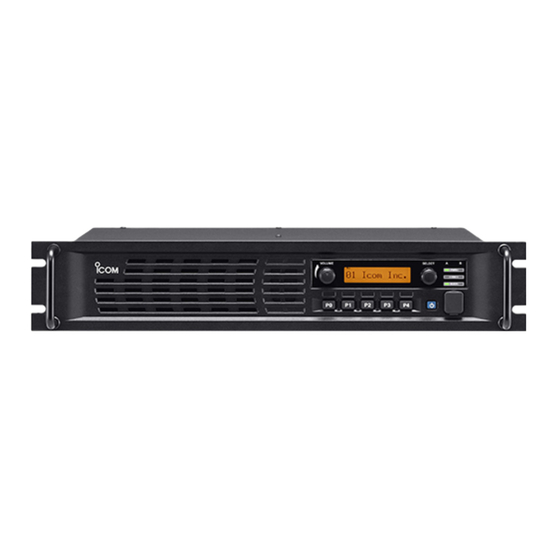
Summary of Contents for Icom FR5000
- Page 1 (Includes Trunking)
-
Page 2: Table Of Contents
Table of Contents What is Covered in this Guide ..........................1 Before You Start Programming ..........................1 Applicable Models ..............................1 Programming Tones in Repeater Mode........................2 Repeater Programming ............................4 Analog Repeating ..............................4 Mixed Analog Repeating ............................. 5 Mixed Digital Repeating............................ -
Page 3: What Is Covered In This Guide
IDAS 6.25kHz digital programming, including IDAS trunking. It covers repeater operation only, though the repeater can be used as a base station. IDAS (Icom Digital Advanced System) is a digital and analog land mobile radio system, using the NXDN™ 6.25kHz digital modulation and common air interface protocol. -
Page 4: Programming Tones In Repeater Mode
Programming Tones in Repeater Mode The FR5000/6000 uses standard analog CTCSS tones and DTCS tones. When in digital mode, the repeater uses RAN codes. RAN Codes are digital equivalents to CTCSS tones. The codes are decimal, and range from 0 to 63. If you want squelch open to be able to receive all RANs, enter 0. This code allows all RAN codes to be received and will retransmit using the code that is programmed for transmit in that channel. - Page 5 Important: If no tones are entered in the Multiple Table field, the radio will respond as described in the following examples. Analog Channels The repeater will receive carrier squelch and will transmit no tones. If there is a tone set in the TX C Tone field (in the Memory CH), the repeater will transmit this tone.
-
Page 6: Repeater Programming
Repeater Programming Analog Repeating A repeater set for analog receives and transmits on analog only. Program your radio with the following settings. All frequencies need to be entered and the squelch level must be set before programming the following settings. Common Window Field Setting / Description... -
Page 7: Mixed Analog Repeating
Mixed Analog Repeating A repeater set for mixed analog is capable of receiving both digital and analog signals, and will re-transmit in the format received. The front hand mic will transmit in Analog. Program your radio with the following settings. All frequencies need to be entered and the squelch level must be set before programming the following settings. -
Page 8: Mixed Digital Repeating
Mixed Digital Repeating A repeater set for mixed digital is capable of receiving both digital and analog signals, and will transmit in the format received. The front hand mic transmissions will be digital. Program your radio with the following settings. All frequencies need to be entered and the squelch level must be set before programming the following settings. -
Page 9: Digital Repeating
Digital Repeating A repeater set for digital receives and transmits in digital only. Program your radio with the following settings. All frequencies need to be entered and the squelch level must be set before programming the following settings. Common Window Field Setting / Description Others >... -
Page 10: Trunking Repeater Programming
Trunking Repeater Programming The following procedure assumes that the squelch has been set. 1. Go to Memory CH and enter your frequencies if you have not already done so. In the Operation Mode field select Full-Duplex. 3. Go to the Common folder and click Common. Set Digital Function to Enable. 4. -
Page 11: Using The External I/O Settings
Using the External I/O Settings The FR5000/6000 cloning software has an interface that allows you to configure ports on the DB-25 connector for external devices. These settings are in the External I/O window. The Port Settings window shows the ports; each port represents a pin on the connector. The CH Switch Table window allows you to change the pin assignment. - Page 12 Port 10 allows you to set power output options for pin 10 of the connector. Power Supply Voltage simply means that the output pin will reflect the voltage on the power supply. The Temperature setting creates an output that varies according to the temperature inside the repeater. Appendix A on page 12 lists the range of temperatures and the corresponding voltages.
-
Page 13: Program Settings
Program Settings This section defines all of the enhanced feature settings for your radio. In most cases, the default settings will work best. Memory CH Window Field Description Suggested Setting RX RAN The receive digital code that must match the TX radio RAN User preference before squelch will open. -
Page 14: Appendix A: Temperature/Voltage Output Chart
Appendix A: Temperature/Voltage Output Chart This table applies when the I/O output of pin 10 is set to Temperature. The following temperatures and voltages are based on a maximum output of 5V, and they vary as the internal temperatures of the repeater changes. -
Page 15: Appendix B: Checking Rssi Levels
Appendix B: Checking RSSI Levels 1. Set a DMM to Vdc RMS. 2. Check the level at pin 10 on the repeater after assigning pin 10 to RSSI, as shown in the following. Voltage Vdc RMS Signal Strength uV @ Pin 1.544 1.416 1.089... - Page 16 ©2008 Icom America Inc. The Icom logo is a registered trademark of Icom Inc. All other trademarks are the property trademark of Icom Inc. All other trademarks are the property trademark of Icom Inc. All other trademarks are the property 2380 116th Ave NE, Bellevue WA, 98004 of their respective owners.


