Advertisement
Available languages
Available languages
Quick Links
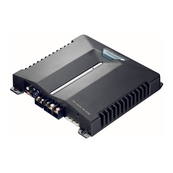
CLASS D MONO AMPLIFIER
AMPLIFICADOR MONO DE CLASE D
Owner's Manual
GM-D510M
Manual del Propietario
PIONEER CORPORATION
4-1, MEGURO 1-CHOME, MEGURO-KU, TOKYO 153-8654, JAPAN
PIONEER ELECTRONICS (USA) INC.
P.O. Box 1540, Long Beach, California 90801-1540, U.S.A.
TEL: (800) 421-1404
PIONEER EUROPE NV
Haven 1087, Keetberglaan 1, B-9120 Melsele, Belgium
TEL: (0) 3/570.05.11
PIONEER ELECTRONICS ASIACENTRE PTE. LTD.
253 Alexandra Road, #04-01, Singapore 159936
TEL: 65-6472-1111
PIONEER ELECTRONICS AUSTRALIA PTY. LTD.
178-184 Boundary Road, Braeside, Victoria 3195, Australia
TEL: (03) 9586-6300
Published by Pioneer Corporation.
PIONEER ELECTRONICS OF CANADA, INC.
Copyright © 2003 by Pioneer Corporation.
300 Allstate Parkway, Markham, Ontario L3R OP2, Canada
All rights reserved.
TEL: (905) 479-4411
Publicado por Pioneer Corporation.
PIONEER ELECTRONICS DE MEXICO, S.A. de C.V.
Copyright © 2003 Pioneer Corporation.
Blvd.Manuel Avila Camacho 138 10 piso
Todos los derechos reservados.
Col.Lomas de Chapultepec, Mexico, D.F. 11000
TEL: 55-9178-4270
Printed in U.S.A.
Impreso en los EE.UU.
<KNKNX> <03L00001>
<HRD0257-A> ES
Before Using This Product
Thank you for purchasing this PIONEER
WARNING
product. Before attempting operation, be
sure to read this manual.
• Always use the special red battery and ground
wire [RD-223], which is sold separately. Connect
In case of trouble
the battery wire directly to the car battery positive
terminal (+) and the ground wire to the car body.
• Do not touch the amplifier with wet hands.
When the unit does not operate properly,
Otherwise you may get an electric shock. Also, do
contact your dealer or the nearest autho-
not touch the amplifier when it is wet.
rized PIONEER Service Station.
• For traffic safety and to maintain safe driving
conditions, keep the volume low enough so that
About This Product
you can still hear normal traffic sound.
• Check the connections of the power supply and
This product is a class D amplifier for the
subwoofer if the fuse of the separately sold bat-
subwoofer. If both L (left) and R (right)
tery wire or the amplifier fuse blows. Detect the
channels are connected to the RCA input
cause and solve the problem, then replace the fuse
of this product, output is mixed because
with another one of the same size and rating.
this product is a mono amplifier.
• To prevent malfunction of the amplifier and sub-
woofer, the protective circuit will cut the power
supply to the amplifier (sound will stop) when an
CAUTION
abnormal condition occurs. In such a case, switch
the power to the system OFF and check the
Never replace the fuse with one of greater
connection of the power supply and subwoofer.
value or rating than the original fuse. Use
Detect the cause and solve the problem.
of an improper fuse could result in over-
• Contact the dealer if you cannot detect the cause.
heating and smoke and could cause dam-
• To prevent an electric shock or short-circuit
age to the product and injury including
during connection and installation, be sure to
burns.
disconnect the negative (–) terminal of the battery
beforehand.
• Confirm that no parts are behind the panel when
drilling a hole for installation of the amplifier. Be
sure to protect all cables and important equipment
such as fuel lines, brake lines and the electrical
wiring from damage.
Setting the Unit
Bass Level Control
If the sound level is too low, even when
the volume of the car stereo used along
with this power amplifier is turned up,
turn bass level control on the front of the
power amplifier clockwise. If the sound
distorts when the volume is turned up,
turn the bass level control counter-clock-
wise.
• When using with an RCA equipped car
stereo (standard output of 500 mV), set to
the NORMAL position. When using with
an RCA equipped Pioneer car stereo with
max. output of 4 V or more, adjust level to
match the car stereo output level.
• When you want to boost bass, turn the bass
level control clockwise.
BFC (Beat Frequency Control) Switch
If you hear a beat while listening to an
AM broadcast with your car stereo,
change the BFC switch using a small
standard tip screwdriver.
Cut Off Frequency Control
You can select a cut off frequency from
40 to 240 Hz.
Power Indicator
The power indicator lights when the
power is switched on.
Advertisement

Related Manuals for Pioneer GM-D510M


Summary of Contents for Pioneer GM-D510M
- Page 1 Detect the channels are connected to the RCA input an RCA equipped Pioneer car stereo with cause and solve the problem, then replace the fuse max. output of 4 V or more, adjust level to of this product, output is mixed because with another one of the same size and rating.
-
Page 2: Connecting The Unit
Connecting the Unit Connection Diagram Connecting the Power Terminal 3. Attach lugs to wire ends. Lugs not Connecting the Speaker Terminals 3. Connect the speaker wires to the CAUTION supplied. speaker terminals. • Always use the special red battery and ground •... -
Page 3: Connecting The Speaker Wires
Connecting the Unit Installation Specifications Connecting the Speaker wires Example of installation on the floor Power source ......................14.4 V DC (10.8 — 15.1 V allowable) CAUTION Grounding system ............................Negative type mat or on the chassis Current consumption ......................31.0 A (at continuous power, 4 Ω) Connect the speaker leads according to the figures shown below. -
Page 4: Antes De Usar Este Producto
Cuando use con un estéreo de automóvil conectan a la entrada RCA de este fusible del amplificador se queman. Detecte la Pioneer equipado con RCA con una salida producto, la salida se mezcla ya que este causa y solucione el problema, y reemplace el máxima de 4 V o más, ajuste el nivel para... - Page 5 Conexión de la unidad Diagrama de conexión Conexión del terminal de 3. Fije las orejetas a los extremos de Conexión del terminal de altavoz 3. Conecte los cables de altavoz al ter- PRECAUCION los cables. Orejetas no suministra- minal de altavoz. alimentación •...
-
Page 6: Conexión De Los Cables De Altavoces
Conexión de la unidad Instalación Especificaciones panel, cuando perfore un orificio para la insta- Conexión de los cables de altavoces Alimentación ......................CC 14,4 V (10,8 — 15,1 V permisible) lación del amplificador. Asegúrese de proteger PRECAUCION Sistema de puesta a tierra ..........................Tipo negativo todos los cables y equipos importantes, tales como Consumo de corriente ......................