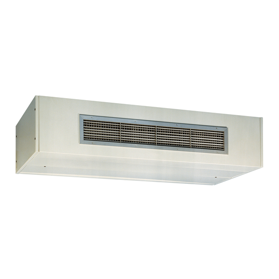
Carrier 40UV Installation, Start-Up And Service Instructions Manual
Unit ventilators with product integrated control (pic)
Hide thumbs
Also See for 40UV:
Table of Contents
Advertisement
Quick Links
Installation, Start-Up and Service Instructions
CONTENTS
SAFETY CONSIDERATIONS . . . . . . . . . . . . . . . . . . . . . . . . . . . .1
INTRODUCTION . . . . . . . . . . . . . . . . . . . . . . . . . . . . . . . . . . . . . . 1,2
PREINSTALLATION . . . . . . . . . . . . . . . . . . . . . . . . . . . . . . . . . . . . .1
Unpack and Inspect Units . . . . . . . . . . . . . . . . . . . . . . . . . . . . . .1
Protect Units From Damage . . . . . . . . . . . . . . . . . . . . . . . . . . . .1
Prepare Jobsite for Unit Installation . . . . . . . . . . . . . . . . . . . .1
PHYSICAL DATA . . . . . . . . . . . . . . . . . . . . . . . . . . . . . . . . . . . . . . . .2
INSTALLATION . . . . . . . . . . . . . . . . . . . . . . . . . . . . . . . . . . . . . .2-24
Placing Vertical Units in Position . . . . . . . . . . . . . . . . . . . . . . .2
Placing Horizontal Units in Position . . . . . . . . . . . . . . . . . . . .2
Make Piping Connections. . . . . . . . . . . . . . . . . . . . . . . . . . . . . . .8
Make Electrical Connections. . . . . . . . . . . . . . . . . . . . . . . . . . . .8
Actuators (Field-Supplied) . . . . . . . . . . . . . . . . . . . . . . . . . . . . . .8
Make Duct Connections . . . . . . . . . . . . . . . . . . . . . . . . . . . . . . 23
Make Final Preparations . . . . . . . . . . . . . . . . . . . . . . . . . . . . . . 24
PRODUCT INTEGRATED CONTROL . . . . . . . . . . . . . . . .24-46
Physical Characteristics . . . . . . . . . . . . . . . . . . . . . . . . . . . . . . 24
Installation and Field Wiring . . . . . . . . . . . . . . . . . . . . . . . . 27
Sensors . . . . . . . . . . . . . . . . . . . . . . . . . . . . . . . . . . . . . . . . . . . . . . 29
Carrier Comfort Network® Interface . . . . . . . . . . . . . . . . . . 38
Relays . . . . . . . . . . . . . . . . . . . . . . . . . . . . . . . . . . . . . . . . . . . . . . . . 39
Actuators . . . . . . . . . . . . . . . . . . . . . . . . . . . . . . . . . . . . . . . . . . . . . 39
Direct Expansion (DX) Cooling. . . . . . . . . . . . . . . . . . . . . . . . 41
DX System Design . . . . . . . . . . . . . . . . . . . . . . . . . . . . . . . . . . . . 41
Electric Heat . . . . . . . . . . . . . . . . . . . . . . . . . . . . . . . . . . . . . . . . . . 42
Remote Start . . . . . . . . . . . . . . . . . . . . . . . . . . . . . . . . . . . . . . . . . 42
Fire/Smoke Status Input . . . . . . . . . . . . . . . . . . . . . . . . . . . . . . 42
Valves . . . . . . . . . . . . . . . . . . . . . . . . . . . . . . . . . . . . . . . . . . . . . . . . 43
START-UP. . . . . . . . . . . . . . . . . . . . . . . . . . . . . . . . . . . . . . . . . . . . . 50
SERVICE. . . . . . . . . . . . . . . . . . . . . . . . . . . . . . . . . . . . . . . . . . . .50-66
Preventing Excessive Condensation on Unit. . . . . . . . . . 50
Check Drain . . . . . . . . . . . . . . . . . . . . . . . . . . . . . . . . . . . . . . . . . . 50
Fan Motor Bearings. . . . . . . . . . . . . . . . . . . . . . . . . . . . . . . . . . . 50
Fan Shaft Ball Bearing . . . . . . . . . . . . . . . . . . . . . . . . . . . . . . . . 50
Clean Fan Wheel. . . . . . . . . . . . . . . . . . . . . . . . . . . . . . . . . . . . . . 50
Clean or Replace Air Filters. . . . . . . . . . . . . . . . . . . . . . . . . . . 50
ECM Motor Removal and Reinstallation. . . . . . . . . . . . . . . 50
Blower Assembly Section Removal
and Reinstallation . . . . . . . . . . . . . . . . . . . . . . . . . . . . . . . . . . 52
Coil Assembly Removal and Reinstallation . . . . . . . . . . . 53
Ball Bearing Replacement . . . . . . . . . . . . . . . . . . . . . . . . . . . . 57
Blower Wheel Removal and Reinstallation . . . . . . . . . . . . 62
Sleeve Bearing Replacement . . . . . . . . . . . . . . . . . . . . . . . . . 63
Damper Section Removal and Reinstallation. . . . . . . . . . 65
TESTING. . . . . . . . . . . . . . . . . . . . . . . . . . . . . . . . . . . . . . . . . . . .67-71
Water Valve Tests . . . . . . . . . . . . . . . . . . . . . . . . . . . . . . . . . . . . . 67
Face and Bypass Damper Tests . . . . . . . . . . . . . . . . . . . . . . 67
Dampers . . . . . . . . . . . . . . . . . . . . . . . . . . . . . . . . . . . . . . . . . . . . . . 68
Fan Tests . . . . . . . . . . . . . . . . . . . . . . . . . . . . . . . . . . . . . . . . . . . . . 68
Filter Maintenance . . . . . . . . . . . . . . . . . . . . . . . . . . . . . . . . . . . . 68
Remote Start Input. . . . . . . . . . . . . . . . . . . . . . . . . . . . . . . . . . . . 68
Sensors . . . . . . . . . . . . . . . . . . . . . . . . . . . . . . . . . . . . . . . . . . . . . . 68
Fire Shutdown Option . . . . . . . . . . . . . . . . . . . . . . . . . . . . . . . . 68
Electric Heat and Direct Expansion Cooling . . . . . . . . . . 68
Mixed-Air Damper Sensors Final Calibration. . . . . . . . . . 69
Testing Completion . . . . . . . . . . . . . . . . . . . . . . . . . . . . . . . . . . . 69
Unit Diagnostics and Troubleshooting . . . . . . . . . . . . . . . . 69
Catalog No. 534-094
Book 3
Tab
2a
with Product Integrated Control (PIC)
Page
. . . . . . . . . . . . . . . . . . . . . . . . . . . . .2
SAFETY CONSIDERATIONS
Installation and servicing of this unit can be hazardous due
to system pressure, electrical components and equipment
location (such as a ceiling or elevated structure). Untrained
personnel can perform the basic maintenance functions of
replacing filters. Only trained and qualified service personnel
should perform all other operations.
When installing this unit, observe precautions in the litera-
ture, tags and labels attached to the equipment, and any other
safety precautions that may apply.
• Follow all safety codes.
• Wear safety glasses and work gloves.
• Use care in handling and installing this accessory.
• Use quenching cloth for all brazing operations.
• Have fire extinguisher available for all brazing
operations.
Before performing service or maintenance operations, turn
off main power switch to the unit. Electrical shock could
cause personal injury.
INTRODUCTION
This document contains general installation instructions for
the 40UV,UH unit ventilators and information and trouble-
shooting of the Product Integrated Control (PIC) option.
See submittal drawings for unit configurations, dimensions,
clearances, and pipe connections. Refer to unit wiring label for
all electrical connections; follow NEC (National Electrical
Code) and local codes.
PREINSTALLATION
Unpack and Inspect Units -
from all units. Check the shipment against shipping order. If
shipment is damaged or incomplete, file claim with transporta-
tion company and advise Carrier immediately.
Protect Units From Damage -
ranty, protect units against adverse weather, theft, vandalism,
and debris on jobsite. Do not allow foreign material to fall into
drain pan. Prevent dust and debris from being deposited on
motor and fan wheels.
If the equipment is stored for any length of time before in-
stallation, it should remain in its shipping container in a clean,
dry, and climate controlled area.
Prepare Jobsite for Unit Installation -
time and to reduce the possibility of costly errors, set up a com-
plete sample installation in a typical room at jobsite. Check all
critical dimensions such as pipe, wire, and duct connection
requirements. Refer to job drawings and product dimension
drawings as required. Instruct all trades in their part of the
installation.
Form 40UV,UH-6SI
Pg 1
40UV,UH050-200
Unit Ventilators
Remove shipping wraps
To maintain war-
7-05
Replaces: 40UV,UH-3SI
To save
Advertisement
Table of Contents

Related Manuals for Carrier 40UV


Summary of Contents for Carrier 40UV
-
Page 1: Table Of Contents
Carrier Comfort Network® Interface ....38 Relays ..........39 Actuators . -
Page 2: Identify And Prepare Units
Refer to the unit nameplate and wiring diagram. unit to the wall using the in. mounting holes in the 2. Remove front (40UV) or bottom (40UH) access panels back panel. from the unit. Retain the -in. socket head fasteners and 7. - Page 3 Box includes fan speed switch, On/Off switch and 31.67 non-fused disconnect switch. 1000 46.74 5. Connection hand is determined by facing discharge of unit. 1250 61.81 1500 78.47 Fig. 1 — 40UV Dimensions — 16 -in. Deep Units (Standard)
- Page 4 Box includes fan speed switch, On/Off 31.67 switch and non-fused disconnect switch. 1000 46.74 5. Connection hand is determined by facing dis- 1250 61.81 charge of unit. 1500 78.47 Fig. 2 — 40UV Dimensions — 21 -in. Deep Units (With Piping Chase)
- Page 5 4 PLACES) 2.27 3.00 5.00 REAR OUTSIDE AIR OPENING (OPTIONAL) 5.75 REAR RETURN AIR OPENING (OPTIONAL) LEGEND CCN — Carrier Comfort Network® REAR VIEW NOTES: DIMENSIONS (in.) APPROXIMATE APPROXIMATE 1. All dimensions are in inches. UNIT AIRFLOW SHIPPING INSTALLED 2. Dimension does not include end panels.
- Page 6 6.75 (TYP) 2.27 REAR OUTSIDE AIR 3.00 5.00 OPENING (OPTIONAL) REAR RETURN AIR 5.75 OPENING (OPTIONAL) REAR VIEW LEGEND CCN — Carrier Comfort Network® NOTES: DIMENSIONS (in.) APPROXIMATE APPROXIMATE 1. All dimensions are in inches. UNIT AIRFLOW DEPTH SHIPPING INSTALLED 2.
- Page 7 (MOUNTING HOLES- TYP-4 PLACES) 2.27 REAR OUTSIDE AIR 3.00 5.00 OPENING (OPTIONAL) REAR RETURN AIR LEGEND 5.75 OPENING (OPTIONAL) CCN — Carrier Comfort Network® REAR VIEW NOTES: DIMENSIONS (in.) APPROXIMATE APPROXIMATE UNIT AIRFLOW DEPTH 1. All dimensions are in inches. SHIPPING...
-
Page 8: Make Piping Connections
See Fig. 8A and 8B for typical wiring connections for basic Check interior unit piping for signs of leakage from shipping unit with CCN (Carrier Comfort Network®) controls. damage or mishandling. If leaks are found, notify a Carrier Actuators (Field-Supplied) — Field-supplied actuators representative before initiating any repairs. - Page 9 Table 2 — Electric Heater Data for Units with PSC Motor NUMBER TOTAL NOMINAL UNIT MOCP CAPACITY V/Ph/Hz ELEMENTS (kW) 17.2 21.5 22.2 27.8 208/1/60 27.3 34.1 32.3 40.4 19.5 24.4 25.3 31.7 240/1/60 31.2 39.0 37.0 46.3 16.8 21.0 21.8 27.3 277/1/60...
- Page 10 44.2 240/1/60 43.7 54.6 10.0 52.0 65.0 12.0 23.3 29.1 30.5 38.1 277/1/60 37.7 47.1 10.0 44.9 56.2 12.0 40UV,UH075 (at 750 Cfm) 14.5 18.2 21.7 27.2 208/3/60 27.0 33.8 27.0 33.8 16.5 20.6 24.8 31.0 240/3/60 30.9 38.6 10.0 30.9...
- Page 11 240/1/60 57.6 72.0 13.3 68.7 85.8 16.0 30.5 38.1 40.1 50.1 10.7 277/1/60 49.7 62.2 13.3 59.4 74.2 16.0 40UV,UH100 (at 1000 Cfm) 18.7 23.4 28.3 35.4 208/3/60 35.4 44.3 10.0 35.4 44.3 11.9 21.3 26.6 32.4 40.5 10.7 240/3/60 40.5...
- Page 12 71.4 89.3 16.7 85.3 106.7 20.0 37.7 47.1 10.0 49.7 62.2 13.3 277/1/60 61.8 77.2 16.7 73.8 92.2 20.0 40UV,UH125 (at 1250 Cfm) 22.9 28.6 34.9 43.6 10.0 208/3/60 43.7 54.7 12.5 43.7 54.7 15.0 26.1 32.6 10.0 40.0 50.0 13.3...
- Page 13 — — — — 44.9 56.2 12.0 59.4 74.2 16.0 277/1/60 73.8 92.3 20.0 — — — — — 40UV,UH150 (at 1500 Cfm) 27.0 33.8 41.5 51.9 12.0 208/3/60 52.1 65.1 15.0 52.1 65.1 18.0 30.9 38.6 12.0 47.6 59.5 16.0...
- Page 14 Table 3 — Electric Heater Data for Units with ECM NUMBER TOTAL NOMINAL UNIT MOCP CAPACITY V/Ph/Hz ELEMENTS (kW) 16.5 20.6 21.5 26.9 208/1/60 26.6 33.2 31.6 39.5 18.8 23.5 24.6 30.8 240/1/60 30.5 38.1 36.3 45.4 16.3 20.3 21.3 26.6 277/1/60 26.4...
- Page 15 44.5 240/1/60 44.0 55.0 10.0 52.3 65.4 12.0 23.7 29.6 30.9 38.6 277/1/60 38.1 47.6 10.0 45.3 56.7 12.0 40UV,UH075 (at 750 Cfm) 14.8 18.5 22.0 27.6 208/3/60 27.3 34.2 27.3 34.2 16.8 20.9 25.1 31.4 240/3/60 31.2 39.0 10.0 31.2...
- Page 16 240/1/60 58.2 72.7 13.3 69.3 86.6 16.0 31.2 39.0 40.8 51.0 10.7 277/1/60 50.4 63.1 13.3 60.1 75.1 16.0 40UV,UH100 (at 1000 Cfm) 19.3 24.1 28.9 36.2 208/3/60 36.0 45.0 10.0 36.0 45.0 11.9 21.9 27.3 33.0 41.2 10.7 240/3/60 41.1...
- Page 17 72.7 90.9 16.7 86.6 108.3 20.0 39.0 48.7 10.0 51.0 63.8 13.3 277/1/60 63.1 78.8 16.7 75.1 93.9 20.0 40UV,UH125 (at 1250 Cfm) 24.2 30.2 36.2 45.3 10.0 208/3/60 45.0 56.3 12.5 45.0 56.3 15.0 27.4 34.2 10.0 41.3 51.6 13.3...
- Page 18 — — — — 46.2 57.8 12.0 60.7 75.8 16.0 277/1/60 75.1 93.9 20.0 — — — — — 40UV,UH150 (at 1500 Cfm) 28.3 35.4 42.8 53.5 12.0 208/3/60 53.4 66.7 15.0 53.4 66.7 18.0 32.2 40.3 12.0 48.9 61.1 16.0...
- Page 19 Table 3 — Electric Heater Data for Units with ECM (cont) NUMBER TOTAL NOMINAL UNIT MOCP CAPACITY V/Ph/Hz ELEMENTS (kW) 50.1 62.7 64.6 80.7 12.0 208/1/60 79.0 98.8 15.0 93.5 116.8 18.0 56.8 71.0 12.0 73.5 91.8 16.0 240/1/60 90.1 112.7 20.0 —...
- Page 20 Table 4 — Motor Data PSC MOTORS MAX FUSE SIZE UNIT 40UV,UH SIZE MOTOR Hp VOLTAGE MOP (Amps) (Amps) 050* 208/230 208/230 208/230 208/230 208/230 MAX FUSE SIZE UNIT 40UV,UH SIZE MOTOR Hp VOLTAGE MOP (Amps) (Amps) 050* 208/230 208/230 208/230 10.6...
-
Page 23: Make Duct Connections
Table 5 — Unit Ventilator Airflow — PSC Motor* FACTORY SETTINGS — CHILLED WATER COIL APPLICATIONS Approximate Air Delivery (Cfm) Unit Speed 1-Row 2-Row 3-Row 4-Row 5-Row 6-Row 7-Row 40UV050 High 40UV,UH075 High 1064 1033 1001 1013 40UV,UH100 High 1295 1285 1215 1218 1239 1250... -
Page 24: Make Final Preparations
Ball valves may be used Carrier’s 40UV,UH unit ventilators with factory-installed as shutoff valves. controls are ETL listed and listed to UL standard 1995 for heat- 9. - Page 25 Table 7 — Standard Control Offerings All control offerings provide the following features: 1. A 3-speed automatic fan control that minimizes fan noise by 6. Proportional Integrated Derivative (PID) logic heating, cooling matching the fan speed to the load. This process provides and damper controls to maintain temperature.
-
Page 27: Unit Ventilator Comfort Control Module
Table 10 — Control Board Terminal Designations CONTROL BOARD CONTROL BOARD FUNCTION FUNCTION TERMINAL TERMINAL Space Temperature (+) Fire/Smoke Status Space Temperature (Gnd) Freezestat Supply-Air Temperature (+) Changeover Supply-Air Temperature (Gnd) Spare Mixed-Air Temperature (+) Common/Ground Mixed-Air Temperature (Gnd) 24 VDC (External Power Supply) Outdoor-Air Temperature (+) Not Available Outdoor-Air Temperature (Gnd) - Page 28 FAN ON/OFF LEGEND — Normally Closed — Adjust — Normally Open — Air Quality — Return-Air Temperature Sensor — Carrier Comfort Network® Controls — Start/Stop — Common — Supply-Air Temperature Sensor — Enthalpy Sensor — Space Temperature Sensor — Ground —...
-
Page 29: Sensors
Sensors ROOM-AIR TEMPERATURE (RAT) SENSOR — The RAT sensor is factory-installed and factory-wired to the control. It measures the temperature of the air returning to the unit from the space. The sensor consists of a thermistor, encased within an epoxy bead. See Fig. 12. It is mounted behind the front center panel, where it is hidden from view. - Page 30 OUTDOOR-AIR TEMPERATURE (OAT) SENSOR — The The LLT is designed to trip if any 1-ft section of the capil- OAT sensor is factory-installed and factory-wired to the con- lary tube senses cold air at or below the thermostat setting. The trol.
- Page 31 6. Use a three-conductor 20 gage shielded cable. The wire is suitable for distances of up to 500 ft. The standard CCN (Carrier Comfort Network®) communication cable may be used. If the set point adjustment (slide-bar) is not re- quired, then an unshielded, 18 or 20 gage, two-conductor, twisted pair cable may be used.
- Page 32 4. Connect the CCN GND signal wire(s) (WHITE/CLR) to single common thermostat. This feature can be used if multiple Terminal 4. Before wiring the RJ11 plug refer to Carrier units serve a single common area. The thermostat must be Comfort Network® Interface, page 38 for communica- mounted in the common area space for this feature.
- Page 33 JUMPER TERMINALS AS SHOWN RED (TH) SENSOR OVERRIDE CABLE PUSHBUTTON BLK (COM) WHT (SW) SERVICE CONNECTOR SET POINT ADJUSTMENT LEGEND CCN — Carrier Comfort Network® THERMISTOR TEMPERATURE SENSOR COM — Common GND — Ground Fig. 18 — Space Temperature Sensor Wiring...
- Page 34 Use 3-conductor, 20 AWG (American Wire (14.3) (12.7) Gage) minimum, shielded cable as specified in the Carrier Comfort Network® Interface section. See Table 14. Thermostat Remote Room Sensor Option — The installer has the option of mounting the thermostat in a mechanical closet or other location in order to limit access to the device.
- Page 35 LEGEND — Normally Closed — Adjust — Normally Open — Air Quality RAT — Return-Air Temperature Sensor — Carrier Comfort Network® — Start/Stop — Common SAT — Supply-Air Temperature Sensor — Ground SPT — Space Temperature Sensor — Mixed-Air Temperature Sensor —...
- Page 36 T16 and T17. The sensor must be mounted vertically on the wall. The Carrier logo should be oriented correctly when the sensor is properly mounted. DO NOT mount the sensor in drafty areas such as near the unit’s discharge grille, open windows or fans, or over heat...
- Page 37 FAN ON/OFF FAN SPEED LEGEND — Adjust — Normally Closed — Air Quality — Normally Open — Carrier Comfort Network® RAT — Return-Air Temperature Sensor — Common — Start/Stop — Ground SAT — Supply-Air Temperature Sensor — Mixed-Air Temperature Sensor SPT —...
-
Page 38: Carrier Comfort Network® Interface
The normal range is from 400 to 1500 hours. Fig. 26 — CCN Communication Connector Carrier Comfort Network® Interface — The Carrier Comfort Network (CCN) communication bus wiring is supplied and installed by the electrical contractor. It consists of shielded, 3-conductor cable with drain wire. -
Page 39: Relays
UNIT VENTILATOR UNIT VENTILATOR UNIT VENTILATOR 1000 FT MAXIMUM LEGEND CCN — Carrier Comfort Network Fig. 27 — CCN Communication Wiring Relays — The fan relays are an integral component of the FACE AND BYPASS DAMPER ACTUATOR (Fig. 29) —... - Page 40 H F 2 3 B J 0 3 9 M a d e i n S w i t z e r l a n d H F 2 3 B J 0 4 0 b y B e l i m o A u t o m a t i o n M a d e i n S w i t z e r l a n d b y B e l i m o A u t o m a t i o n 35 in-lb (4 Nm)
-
Page 41: Direct Expansion (Dx) Cooling
Recommendations for basic DX system design and piping should always be followed and are available in the Carrier System Design manual. The Unit Ventilator Comfort Control module maintains the space temperature at the cooling set point by operating the DX stages as the space load requires. -
Page 42: Electric Heat
Electric Heat — wired into the fan motor circuit and the other set is wired to the Two control relays are factory-supplied, control input. The control box provides 24 vac power for the factory-installed and factory-wired to provide staging control relay. -
Page 43: Valves
Valves WATER VALVES — Water valve assemblies are shipped with the unit for field installation. All factory-supplied valves The manual positioning lever on all water valves should are fully modulating and capable of being positioned at any only be used when controller power is OFF. DO NOT point within the travel range of the valve. - Page 44 WATER COIL RETURN SUPPLY 3-WAY VALVE RETURN WATER COIL SUPPLY 2-WAY VALVE NOTE: Dimensions are in inches (mm). Fig. 33 — Typical Piping for Spring Return 2-Way and 3-Way Mixing Valves Fig. 34 — Water Valve Dimensions (Modulating Type) The valve type is identified by the first digit of the two-digit For pressure drops other than those tested, see Table 19.
- Page 45 Table 19 — Valve and Coil Pressure Drops vs Flow Table 20 — 2-Way Water Valve Specifications and Ratings TYPICAL VALVE UNIT VALVE AND COIL SIZE COIL FLOW SUPPLIED CLOSE-OFF PRESSURE DROP (NOMINAL ROWS COEFFICIENT NORMAL (Cv) APPLICATION PRESSURE CFM) VOLUME POSITION OPEN...
-
Page 46: Set-Up, Configuration, And Operation
Heating, Refrigeration — Mixed Air Temperature Number and Air Conditioning Sensor Sup Bus — Supervisory Bus Engineers — Medium Number — Carrier Comfort Network® — minute Sup Ele — Supervisory Element — Configured Norm — Normal Number Cntrl — Control —... - Page 47 Table 23 — CCN Device Configuration SOFTWARE DEVICE NAME DESCRIPTION LOCATION PART NUMBER Comfort 40UV/UH System Unit CESR-131191-02 Ventilator NOTE: The device name, description, and location fields can be modified by the Building Supervisor or ComfortWORKS® software. Table 24 — Service Configuration...
- Page 48 Table 25 — Alarm Service Configuration DESCRIPTION POINT NAME STATUS / UNITS RANGE DEFAULT Alarm Routing Control ALRMCNT xxxxxxxx 0 - 1* 11010000 Realarm Time REALARM 1-255† Cntrl Temp Hys xx.x Supply Air Temperature SPTHYS 1.0 - 20.0 Lo Lim LOWLIM xxx.x °F...
- Page 49 Table 27 — CCN Configuration DESCRIPTION POINT STATUS / UNITS RANGE DEFAULT Warm-Up Temp Check WARMENAB Disable/Enable 0 - 1* Enable Unoccupied Fan Cycling FAN_CYCL Disable/Enable 0 - 1* Disable Unoccupied Free Cooling NTEN Disable/Enable 0 - 1* Enable Free Cooling Lock-out NTLO xx.x °F...
-
Page 50: Start-Up
(if supplied). If unit is connected to ductwork, the motor to provide proper cooling. Never run the remove front (40UV) or bottom (40UH) panel, separate fan motor without the cooling shroud in place. Ensure shaft from motor at bushing, remove motor, and slide fan the shroud inlet ring does not touch the motor;... - Page 51 1. All dimensions shown in inches. 2. Not all components shown for clarity. 3. Motor shroud not shown for clarity. Install prior to operation. 4. Refer to Fig. 42 for cooling shroud installation. Fig. 36 — 40UV,UH Ventilator Blower Section Assembly — ECM Motor Detail...
- Page 52 11. Remove the four nuts retaining the blower section to the shroud be installed prior to operation of the motor. Ensure back (40UV) or top (40UH) frame. See Item 3 in Fig. 37. the venturi is installed on the motor shroud.
-
Page 53: Coil Assembly Removal And Reinstallation
(40UV,UH150 units only). See Item 6 in Fig. 38. 2. Remove all front (40UV) or bottom (40UH) panels. Re- move end panels. 4. Reinstall two carriage bolts that attach the front brace to the frame sides. - Page 54 FRONT BRACE PIPE CHASE NOTES: 1. Unit shown in vertical orientation. Drawing applies to horizontal and vertical units. 2. Not all components shown for clarity. 3. 40UV,UH125-200 units only. COIL SECTION BLOWER SECTION Fig. 37 — 40UV,UH Ventilator Blower Section...
- Page 55 2. This drawing applies to 1500 cfm units only. 3. Remove shaft, motor, and coupling prior to bearing removal. 4. Refer to Fig. 36 and 43 for motor-coupling and coupling-shaft tolerances. DETAIL A Fig. 38 — 40UV,UH Ventilator Inboard Bearing (40UV,UH150 Only)
- Page 56 (SEE NOTE 3) DAMPER SECTION NOTES: 1. Unit shown in vertical orientation. Drawing applies to horizontal and vertical units. COIL SECTION 2. Not all components shown for clarity. 3. 40UV,UH125-150, 40UH200 units only. Fig. 39 — 40UV,UH Ventilator Coil Section...
-
Page 57: Ball Bearing Replacement
17. Re-attach green ground wire that connects the motor to 2. Remove front (40UV) or bottom (40UH) panels and right the frame with in. head screw if unit has a PSC motor. - Page 58 (SEE NOTE 5) (SEE NOTE 5) (SEE NOTE 4) UNIT BOTTOM NOTES: 1. Not all components shown for clarity. 2. This drawing applies to 2000 cfm units only. 3. Remove shaft, motor and coupling prior to removing bearing. Refer to Ball Bearing Replacement instructions. 4.
- Page 59 3. Install motor with capacitor facing up. 4. Install sleeve bearing with oil cup facing up and towards the rear of the assembly. Fig. 41 — 40UV,UH Ventilator Blower Drive Train Assembly — 40UV050-150 and 40UH075-150 Units (PSC Motor)
- Page 60 3. Install motor with electrical connections facing front of assembly. 4. Install oil cup facing up and towards the rear of the assembly. LEFT SIDE VIEW Fig. 42 — 40UV,UH Ventilator Blower Drive Train Assembly — 40UV050-150 and 40UH075-150 Units (ECM Motor)
- Page 61 MOTOR (PSC) + – 0.500 0.063 FACE OF MOTOR FLUSH WITH FACE OF INSULATION NOTES: 1. All dimensions shown in inches. 2. Not all components shown for clarity. Fig. 43 — 40UV,UH Ventilator Blower Section Assembly — PSC Motor Detail...
-
Page 62: Blower Wheel Removal And Reinstallation
Tighten the two bearing setscrews (only on blower housing(s) (Fig. 44, Item 7) to blower deck 40UV,UH150 and 200 size units). See Fig. 38, 40 or 44. (Fig. 44, Item 3) and remove blower and wheel assembly. 20. Reinstall the coil baffle using the six in. -
Page 63: Sleeve Bearing Replacement
(Allen) tool or in. nut driver to remove unrestricted and can rotate freely. Check for any fan front (40UV) or bottom (40UH) panels and right (motor obstructions. end) end panel. 12. Reinstall left blower section end insulation (Item 1 in 3. - Page 64 2. Supplied on electric heat units only. MOTOR AND OPENING COUPLING 3. Secure capillary tubes to blower housing using high temperature SETSCREW cable tie. Capillary tube lengths will vary depending on unit size. ACCESS Fig. 44 — 40UV,UH Ventilator Blower Section Assembly Sheet Metal (All Units)
-
Page 65: Damper Section Removal And Reinstallation
(Allen) tool or in. nut driver to remove 5. Replace the two in. head screws securing kickplate front (40UV) or bottom (40UH) panels and right end to the damper sides (one on each side) and remove panels. kickplate. - Page 66 COIL BAFFLE DAMPER SECTION COIL SECTION BLOWER SECTION DAMPER SECTION KICKPLATE NOTES: 1. Unit shown in vertical orientation. Drawing applies to horizontal and vertical units. 2. Not all components shown for clarity. Fig. 45 — 40UV,UH Ventilator Damper Section Removal/Installation...
-
Page 67: Testing
The Unit Ventilator Comfort Control module is designed for fully closed while the unit is unoccupied and the fan is OFF. easy checkout and commissioning using the Carrier Comfort Using the Network Service Tool, page down to the bottom of Network®... -
Page 68: Dampers
sticking or binding. After the damper reaches the full coil face To reset the alarm after the filters have been serviced, use position, select the HEATING 2 output and force it to ON. The the Network Service Tool and select the filter status from the force placed earlier on the HEATING 1 output should be re- Status Display screen. -
Page 69: Mixed-Air Damper Sensors Final Calibration
1. Set the control switch to the OFF position and using the Network Service Tool, select the Display screen Unit Diagnostics and Troubleshooting — and verify the FAN STATUS and FAN RELAY both Table 30 for 40UV,UH diagnostics and troubleshooting read OFF. information. - Page 70 Table 30 — Unit Diagnostics And Troubleshooting PROBLEM POSSIBLE CAUSE CORRECTIVE ACTION Unit Does Not Operate Power to control is OFF Check local disconnect or circuit breaker. Remote Start/Stop (S/S) jumper not installed (for Install jumper between T20 on control module and TB stand-alone operation only) (24 vac).
- Page 71 Table 30 — Unit Diagnostics and Troubleshooting (cont) PROBLEM POSSIBLE CAUSE CORRECTIVE ACTION Indoor Air Quality (IAQ) IAQ not enabled Enable IAQ control operation. Features Malfunctioning Set point too high/too low Adjust the set point to the correct value. Space or return air temperature too high/low Control will resume when space/returns temperatures recover.
-
Page 72: Manufacturer Reserves The Right To Discontinue, Or Change At Any Time, Specifications Or Designs Without Notice And Without Incurring Obligations
Copyright 2005 Carrier Corporation Manufacturer reserves the right to discontinue, or change at any time, specifications or designs without notice and without incurring obligations. Book 3 Catalog No. 534-094 Printed in U.S.A. Form 40UV,UH-6SI Pg 72 1-06A 7-05 Replaces: 40UV,UH-3SI...