
Related Manuals for Moffat Blue Seal TURBOFAN 30M Series


Summary of Contents for Moffat Blue Seal TURBOFAN 30M Series
- Page 1 E 3 0 M 3 ( M a n u a l O p e r a t i o n ) I n s t a l l a t i o n a n d O p e r a t i o n M a n u a l 238760-4...
- Page 2 The reproduction or copying of any part of this manual by any means whatsoever is strictly forbidden unless authorized previously in writing by the manufacturer. In line with policy to continually develop and improve its products, Moffat Ltd. reserves the right to change the specifications and design without prior notice.
- Page 3 Contents List E30M3 - Turbofan Oven - 3 Tray Convection Oven. Safety Information Installation Requirements Unpacking Location Clearances Stand Mounted Ovens Electrical Connection Positioning and Levelling of Oven Initial Start-Up Commissioning Operation Guide Oven Control Panel Description of Controls Using the Oven Cleaning Guidelines Oven Cleaning Periodic Maintenance...
- Page 4 Introduction Before using your new oven, please read this instruction This manual must be kept by the owner for future manual carefully, pay particular attention to any information reference. labelled ‘WARNING’, ‘CAUTION’, ‘IMPORTANT’ or Date of Purchase, Date of Installation A record of the ‘NOTE’...
-
Page 5: Specifications
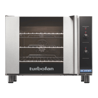
Specifications E30M3 Tray Capacity Tray Spacing 3 x GN 1/1 Pan 230-240V, 1P+N+E, 50/60HZ, 9.5A, 2.3 kW 100mm 3 x US ½ Pan... -
Page 6: Installation
Installation Installation shall comply with local electrical, health and safety requirements. It is most important that this oven is installed correctly and that oven operation is correct before use. If you have any questions regarding the proper installation and / or operation of this oven, please contact your local Turbofan distributor. - Page 7 Installation This oven must be earthed / grounded. If the supply cord is damaged, it must be replaced by a suitably qualified person in order to avoid a hazard. Each oven should be connected to an adequately protected power supply and an isolation switch mounted adjacent to, but not behind the oven and must be readily accessible to the operator.
-
Page 8: Operation
Operation Turbofan Ovens have been designed to provide simple operation. This oven is intended for use in a commercial kitchen and must only be put to the use for which it was intended, i.e. cooking food product. To use this oven correctly please read the following sections carefully:- Power ‘On’... - Page 9 Operation To Turn ‘On’ the Oven;- Rotate ‘Temp’ Control from the ‘Off’ position. ‘Power On’ Indicator light illuminates. To Set the Temperature;- Rotate ‘Temp’ Control to the temperature required. ‘Oven Heating’ indicator light will remain ‘On’ until the oven is up to temperature. To Load the Oven;- open oven door and load prod- uct.
-
Page 10: Cleaning And Maintenance
Cleaning and Maintenance d. Clean all racks with a mild anti bacterial detergent and hot water, using a soft bristled brush. e. Dry the racks thoroughly with a dry cloth. f. To refit the side racks, engage the locating pins at the rear of side rack into the locating holes in the rear of the oven. - Page 11 Cleaning and Maintenance Door Seal Door Glass Cleaning a. To remove door seal, pull the 1 piece seal forward Ensure that the oven door is cool before cleaning until it pulls out of the location groove around the oven. Note the way the seal is fitted to the oven, the oven door glass.
-
Page 12: Fault Finding
Fault Finding You may encounter a problem not covered in this section, please This section provides a reference to the more common problems that may occur during the operation of your oven. This fault contact your service provider who will require the following finding guide is intended to help you correct and accurately information:- diagnose problems with your oven. -
Page 13: Electrical Schematics
Electrical Schematics... -
Page 14: Replacement Parts List
Replacement Parts List Only genuine authorized replacement parts should be used for the servicing and repair of this oven. The instructions supplied with the parts should be followed when replacing components. For further information and servicing instructions, contact your nearest authorized service provider or Turbofan Dealer. When ordering replacement parts, please quote the part number and the description as listed below. -
Page 15: Appendix 1 - Oven Door Reversal
Appendix 1 - Oven Door Reversal 11. Remove inner glass latching studs and fit to opposite side of door using Loctite Refit all screw fasteners using a low-mid strength 243 to secure. thread locking adhesive unless otherwise stated. Door reversal should only be carried out by a suitably competent person. - Page 16 Appendix 1 - Oven Door Reversal 18. Remove Blanking Screw and Door Catch from front of oven and swap around (refer ‘Adjusting Door Catch’). Check alignment and operation of the door. Ensure that the door is correctly aligned horizontally and vertically. Door Catch Blanking Screw 1.