
Related Manuals for ATEN PN5212


Summary of Contents for ATEN PN5212
- Page 1 Power Over the NET™ PN5212 / PN5320 Power Distribution Unit User Manual www.aten.com...
-
Page 2: Fcc, Ce Information
PN5212 / PN5320 User Manual FCC, CE Information FEDERAL COMMUNICATIONS COMMISSION INTERFERENCE STATEMENT: This equipment has been tested and found to comply with the limits for a Class A digital device, pursuant to Part 15 of the FCC Rules. These limits are designed to provide reasonable protection against harmful interference when the equipment is operated in a commercial environment. -
Page 3: User Information
PN5212 / PN5320 User Manual User Information Online Registration Be sure to register your product at our online support center: International http://eservice.aten.com Telephone Support For telephone support, call this number: International 886-2-8692-6959 China 86-10-5255-0110 Japan 81-3-5615-5811 Korea 82-2-467-6789 North America... -
Page 4: Pn Device Safety Notice
PN5212 / PN5320 User Manual PN Device Safety Notice Set the maximum permissible breaker protection in the building circuitry to the current rating specified on the rating plate. Observe all national regulations and safety codes as well as deviations for breakers. -
Page 5: Package Contents
Copyright © 2010–2013 ATEN® International Co., Ltd. Manual Part No. PAPE-0321-AX2G Printing Date: 2013-12-23 Altusen and the Altusen logo are registered trademarks of ATEN International Co., Ltd. All rights reserved. All other brand names and trademarks are the registered property of their respective owners. -
Page 6: Table Of Contents
PN5212 / PN5320 to PN5212 / PN5320 ....13 PN5212 / PN5320 to PN0108 ......14 Chapter 3. - Page 7 Logging In ..........19 The PN5212 / PN5320 Main Page ......20 Page Components .
- Page 8 PN5212 / PN5320 User Manual Creating Groups ......... 50 Modifying Groups .
- Page 9 PN5212 / PN5320 User Manual Account Policy ......... . 79 Private Certificate .
- Page 10 PN5212 / PN5320 User Manual Help ..........102 The Log Server Main Screen .
- Page 11 PN5212 / PN5320 User Manual Administrator Login Failure ........133 Specifications .
-
Page 12: About This Manual
PN5212 / PN5320 User Manual About This Manual This User Manual is provided to help you get the most from your PN5212 / PN5320 system. It covers all aspects of installation, configuration and operation. An overview of the information found in the manual is provided below. -
Page 13: Conventions
Chapter 11, Out of Band Operation, explains an alternative method to access the PN5212 / PN5320 in case the LAN that it resides on goes down, or it cannot be accessed with the usual browser based method for some reason. -
Page 14: Product Information
PN5212 / PN5320 User Manual Product Information For information about all ALTUSEN products and how they can help you connect without limits, visit ALTUSEN on the Web or contact an ALTUSEN Authorized Reseller. Visit ALTUSEN on the Web for a list of locations and telephone numbers International –... -
Page 15: Chapter 1. Introduction
Serial access via modem, Telnet and SSH is also supported to ensure system availability. Since the PN5212 / PN5320 firmware is upgradeable over the Net, you can stay current with the latest functionality improvements simply by downloading updates from our website as they become available. -
Page 16: Features
Space saving 0U rack mount design IEC or NEMA outlet models Daisy chain up to 15 additional stations for up to 192 (PN5212) or 320 (PN5320) outlets 2 x 7 segment front panel LED shows Station ID and Current / Voltage /... -
Page 17: Management
Chapter 1. Introduction Power-on sequencing - users can set the power on sequence and delay time for each port to allow equipment to be turned on in the proper order Auto-Ping function to determine device status Easy setup and operation via a browser-based user interface Multibrowser support (IE, Mozilla, Firefox, Chrome, Safari, Opera, Netscape) Telnet and SSH access for text menu configuration and outlet level... -
Page 18: Security
Remote authentication support: RADIUS, TACACS+, LDAP, LDAPS and Active Directory Requirements Browsers accessing the PN5212 / PN5320 must support SSL 128 bit encryption. For cold booting of attached computers, the computer's BIOS must support Wake on LAN or System after AC Back. -
Page 19: Components
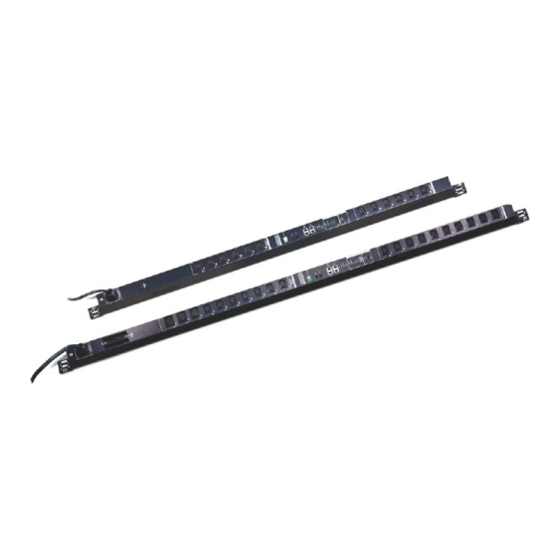
Chapter 1. Introduction Components Front View PN5320 - NEMA PN5320 - IEC... - Page 20 Power Cord Plug the cord into your AC source. Note: The Front View diagram depicts a PN5320. The PN5212 is basically the same, except there are only 12 AC power sockets (6 on each side of the Port and LED panel), and all the sockets are NEMA 5-15R or IEC320 C13.
-
Page 21: Port And Led Panel
Press the button above the display window to cycle the selection among the items. Status Power: Lights when the PN5212 / PN5320 is powered up and LEDs and ready to operate. Reset Link: Lights GREEN to indicate that a connection via the Switch PN5212 / PN5320's RJ-45 Ethernet port has been established. - Page 22 Port device plugs in here. If the child device is a PN0108, you must use an SA0150 adapter to plug into the PN0108’s PON In port (see PN5212 / PN5320 to PN0108, page 14, for details). RS-232/ Selects which protocol the PON In / Console port uses.
-
Page 23: Chapter 2. Hardware Setup
à partir du clavier. Rack Mounting The PN5212 / PN5320 can be installed in a 0U configuration on the side of a rack. To rack mount the device, use the rack mounting brackets that came with your device. - Page 24 PN5212 / PN5320 User Manual (Continued from previous page.) The PN5212 / PN5320 comes supplied with top and bottom screws already inserted, as shown below: If you want to mount to brackets at the top and bottom ends of the device, you...
-
Page 25: Single Stage Installation
2. For each device you want to connect, use its power cable to connect from the device's AC socket to any available outlet on the PN5212 / PN5320. 3. Plug the cable that connects the PN5212 / PN5320 to the LAN into the PN5212 / PN5320's LAN port. - Page 26 PN5212 / PN5320 User Manual SA0151 (DTE)
-
Page 27: Daisy Chaining
100 m. PN5212 / PN5320 to PN5212 / PN5320 Up to 15 additional PN5212 / PN5320 stations can be daisy chained down from the top level (master) device – allowing up to 320 outlets to be managed on a complete installation. -
Page 28: Pn5212 / Pn5320 To Pn0108
To daisy chain a child PN0108 from a parent PN5212 / PN5320, do the following: 1. Use Cat 5e cable to connect the PN5212 / PN5320’s PON OUT port to the SA0150 Adapter supplied with your package. 2. Connect the SA0150 to the PN0108’s PON IN port. -
Page 29: Super Administrator Setup
Chapter 3 Super Administrator Setup First Time Setup Once the PN5212 / PN5320 installation has been cabled up, the next tasks the Administrator needs to perform involve configuring the network parameters, changing the default Super Administrator login settings, and adding users. -
Page 30: Network Configuration
PN5212 / PN5320 User Manual Network Configuration To set up the network, do the following: 1. Click the Device Management tab. 2. Select Network on the menu bar. A screen similar to the one below appears: 3. Fill in the fields according to the information provided under Network,... -
Page 31: Changing The Administrator Login
Chapter 3. Super Administrator Setup Changing the Administrator Login To change the default Super Administrator username and password, do the following: 1. Click the User Management tab. The User Management page has a list of Users and Groups in the Sidebar at the left, and a more detailed list of users –... -
Page 32: Moving On
PN5212 / PN5320 User Manual (Continued from previous page.) The User General page appears: 3. Change the Username and Password to something unique. 4. Re-enter the password to confirm it is correct. 5. Click Save. 6. When the dialog box informing you that the change completed successfully appears, Click OK. -
Page 33: Logging In
Note: Browsers must support SSL 128 bit encryption. To access the PN5212 / PN5320 do the following: 1. Open your browser and specify the IP address of the PN5212 / PN5320 you want to access in the browser's URL location bar. -
Page 34: The Pn5212 / Pn5320 Main Page
PN5212 / PN5320 User Manual The PN5212 / PN5320 Main Page After you have successfully logged in, the PN5212 / PN5320 Main Page comes up with the Outlet Access Connections page displayed: Note: 1. The screen depicts a Super Administrator’s page. Depending on a user’s type and permissions, not all of these elements appear. -
Page 35: Page Components
Chapter 4. Browser Login Page Components The web page screen components are described in the table, below: Item Description Tab Bar The tab bar contains the Power Over the NET™’s main operation categories. The items that appear in the tab bar are determined by the user’s type, and the authorization options that were selected when the user’s account was created. - Page 36 PN5212 / PN5320 User Manual This Page Intentionally Left Blank...
-
Page 37: Chapter 5. Outlet Access
Outlet Access Overview When you log in to the PN5212 / PN5320, the UI opens with its default selection of the Outlet Access tab; the Connections menu; and the Outlets submenu. The contents of the Outlets submenu are displayed in the main panel. -
Page 38: The Outlet Selection Sidebar
PN5212 / PN5320 User Manual The Outlet Selection Sidebar All stations and their outlets – including cascaded stations and their outlets – are listed in a tree structure in the Sidebar at the left of the screen. Outlet groups are listed at the bottom of the tree: Users are only allowed to see the stations and outlets that they have access permission for. -
Page 39: Manual Power Management
Chapter 5. Outlet Access The outlet’s icon color indicates its status as explained in the table, below: Icon Status Steady Amber Power to the outlet is On. Flashing Amber A change in the outlet's power status is pending. (See Shutdown Method, page 42) Steady Gray Power to the outlet is Off. - Page 40 PN5212 / PN5320 User Manual Group General Page With the exception of the power outlet icon, the pages are view only and provide power status and usage information. To configure the settings, select Configuration at the far right of the menu bar. See Configuration, page 37 for details.
-
Page 41: Connections
Chapter 5. Outlet Access Connections The Connections pages provide status and settings information for stations, outlets, and outlet groups. The pages that come up in the main panel differ depending on which item is selected in the Sidebar. Station Level When a station is selected in the Sidebar, the main panel page has three tabs: Outlets, General, and Groups: Outlets... -
Page 42: General
PN5212 / PN5320 User Manual General The station’s General page shows the station’s settings configuration: This page only displays information. Settings changes cannot be made here. To configure the settings, select Configuration at the far right of the menu bar. See... -
Page 43: Groups
Chapter 5. Outlet Access Groups The station’s Groups page lists the names of the outlet groups that have been created with its outlets in the left column. The outlets that make up the group are in the right column: The outlets are displayed as [Station ID-Outlet Number]. For example, [C01- 05] refers to outlet number 5 belonging to station number 1. -
Page 44: Outlet Level
PN5212 / PN5320 User Manual Outlet Level When an outlet is selected in the Sidebar, the main panel tabs change to: General, Configuration, and Scheduling: Each of the tabs is described below. General The outlet’s General page provides information regarding the outlet’s name... -
Page 45: Configuration
Chapter 5. Outlet Access Configuration The outlet’s Configuration page summarizes the various configuration settings that have been made for the outlet: The Configuration section only displays information. Setting changes cannot be made here. To configure the settings, select Configuration at the far right of the menu bar. -
Page 46: Scheduling
PN5212 / PN5320 User Manual Scheduling The outlet’s Scheduling page shows the date and time schedule settings for automatic power control of the outlet: To configure the schedule, select Configuration at the far right of the menu bar. See Schedule, page 43 for details... -
Page 47: Outlet Group Level
Chapter 5. Outlet Access Outlet Group Level When an outlet group is selected in the Sidebar, the main panel tabs change to General, and Schedule. Each of the tabs is described below. General The outlet group’s General page provides information regarding the group’s name, the outlets that belong to the group, and the power status of the outlets: You can manually turn the outlets On and Off from this page by clicking the power outlet icon (see Manual Power Management, page 25 for details). -
Page 48: User Preferences
Logout Timeout If there is no user input for the amount of time set with this function, the user is automatically logged out. A login is necessary before the PN5212 / PN5320 can be accessed again. Key in a value from 0–180 minutes. -
Page 49: Sessions
Chapter 5. Outlet Access Sessions The Session page shows all of the users currently logged into the PN5212 / PN5320, and provides information about each of their sessions. The information under the IP heading indicates the IP address that the user is logged in from. -
Page 50: Outlet Level
PN5212 / PN5320 User Manual Outlet Level When an outlet is selected in the Sidebar, a page similar to the one below, comes up in the main panel: Users and groups are listed alphabetically in the left column. A check mark under the Access column, indicates the user or group is authorized to access and power control the selected outlet. -
Page 51: Configuration
Chapter 5. Outlet Access Configuration The Configuration page is used to configure the operation of the PN5212 / PN5320 at both the station level and the individual power outlet level. The items available differ depending on whether a station or an outlet is selected in the Sidebar. -
Page 52: General
PN5212 / PN5320 User Manual General When the Configuration page opens, the station’s General page is selected. This page allows you to set up a power management configuration for the device as a whole. The meanings of the field headings are given in the... -
Page 53: Groups
Note: In the Outlet column the outlets are displayed as [Station ID-Outlet Number]. For example, [C01-05] refers to outlet number 5 belonging to PN5212 / PN5320 station number 01. This page is also used to create new outlet groups, as well as to modify or delete existing ones. - Page 54 PN5212 / PN5320 User Manual 3. Click to put a checkmark in the checkbox of the outlets you want to add to the group, then click Save. When you return to the Group page, your new group is included in the list: Note: The group also shows up as a device in the Sidebar, and this page can be accessed by clicking on its icon in the Sidebar.
-
Page 55: Outlet Level Configuration
Chapter 5. Outlet Access Outlet Level Configuration The configuration settings for a PN5212 / PN5320 can be specified on an outlet by outlet basis. When an outlet is selected in the Configuration page Sidebar, the main panel displays a page with two tabs: Configuration, and Schedule, as described in the sections that follow. - Page 56 PN5212 / PN5320 User Manual Heading Meaning Power Off Delay Sets the amount of time the PN5212 / PN5320 waits after the Power Button is clicked (see Manual Power Management, page 25), before it turns off the computer attached to the corresponding outlet.
-
Page 57: Schedule
Chapter 5. Outlet Access Schedule Clicking the Schedule tab brings up a page that lets you set up a scheduled power On/Off configuration for the selected outlet: The meanings of the field headings are given in the table, below: Heading Meaning Routine Type Drop down the list to select whether the scheduled power... - Page 58 PN5212 / PN5320 User Manual Heading Meaning Restart Time Key in the time of day you want the restart to take place using the HH:MM format. If you want to temporarily suspend this function without deleting the entry, click to put a check in the Disable checkbox at the right of this field.
-
Page 59: Chapter 6. User Management
Chapter 6 User Management Overview When you select the User Management tab the screen comes up with Accounts selected in the Menu bar, and the User List displayed in the main panel:... -
Page 60: Users
PN5212 / PN5320 User Manual The Accounts page has two menu items: Accounts, for managing individual users; and Groups, for managing user groups. Note: There is a pre-installed super administrator account. It can be used to set up the device and to begin creating users and groups. The Username for this account is administrator;... - Page 61 Chapter 6. User Management 3. Enter the required information in the appropriate fields. A description of each of the fields is given in the table below: Field Description Username From 1 to16 characters are allowed depending on the Account Policy settings. See Account Policy, page 79. Password From 1 to16 characters are allowed depending on the Account Policy settings.
- Page 62 PN5212 / PN5320 User Manual Field Description Status Status allows you to control the user’s account and access to the installation, as follows: Disable Account lets you suspend a user’s account without actually deleting it, so that it can be easily reinstated in the future.
-
Page 63: Modifying User Accounts
Chapter 6. User Management Modifying User Accounts To modify a user account, do the following: 1. In the Sidebar User tree, click the user’s name – or – In the main panel, select the user’s name, then click Modify. 2. In the User page that comes up is the same as the one for adding users (see page 46). -
Page 64: Groups
PN5212 / PN5320 User Manual Groups Groups allow administrators to easily and efficiently manage users and devices. Since device access rights apply to anyone who is a member of the group, administrators need only set them once for the group, instead of having to set them for each user individually. - Page 65 Chapter 6. User Management 4. Enter the required information in the appropriate fields. A description of each of the fields is given in the table below: Field Description Group Name A maximum of 16 characters is allowed. Permissions Group permissions are set by checking the appropriate boxes, as follows: Checking User Management, Device Management, Log, and/or Maintenance gives all group members...
-
Page 66: Modifying Groups
PN5212 / PN5320 User Manual Modifying Groups To modify a group, do the following: 1. In the Sidebar Group tree, click the group’s name – or – In the main panel, select the group’s name, then click Modify. 2. The Groups page that comes up is the same as the one for adding groups (see page 50). -
Page 67: Users And Groups
Chapter 6. User Management Users and Groups There are two ways to assign users to – and remove users from – groups: from the Accounts menu; and from the Groups menu. Note: 1. Before you can assign users to groups, you must first create them. See Adding Users, page 46 for details. -
Page 68: Removing Users From A Group From The Accounts Page
PN5212 / PN5320 User Manual Removing Users From a Group From the Accounts Page To remove a user from a group from the Accounts page, do the following: 1. In the Sidebar Users tree, click the user’s name – or –... -
Page 69: Assigning Users To A Group From The Groups Page
Chapter 6. User Management Assigning Users to a Group From the Groups Page To assign a user to a group from the Groups page, do the following: 1. In the Sidebar User Groups tree, click the group’s name – or – In the main panel, select the group’s name, then click Modify. -
Page 70: Removing Users From A Group From The Groups Page
PN5212 / PN5320 User Manual Removing Users From a Group From the Groups Page To remove a user from a group from the Groups page, do the following: 1. In the Sidebar User Groups tree, click the group’s name – or –... -
Page 71: Device Assignment
Chapter 6. User Management Device Assignment When a user logs in to the Power Over the NET™ device, the interface comes up with the Outlet Access page displayed. All the outlets that the user is permitted to access are listed in the Sidebar at the left of the page. Access permissions for those outlets can be assigned on an outlet-by-outlet basis from the Accounts menu for individual users, or the Groups menu for user groups. -
Page 72: Assigning Device Permissions From The Groups Page
PN5212 / PN5320 User Manual 3. Under the Access column, click to permit or restrict the user’s access to an √ outlet. A check mark ( ) indicates that the user has permission to access the outlet; a blank checkbox means that the user is denied permission to access the outlet. -
Page 73: Chapter 7. Device Management
Chapter 7 Device Management Overview The Device Management page allows super administrators, administrators, and users with device management permission to configure and control overall Power Over the NET™ device operations. Device Information When you click the Device Management tab, the display opens with the Device Information menu page displayed:... - Page 74 PN5212 / PN5320 User Manual The page presents information about the selected device, as described in the following table. Item Meaning Device Name This field lets you give the device a unique name. This can be convenient when you need to differentiate among several devices in multi station installations.
-
Page 75: Network
Chapter 7. Device Management Network The Network page is used to specify the Power Over the NET™ device’s network environment. The main section is divided into 5 panels. Select the device you want to configure in the Sidebar, then fill in the information in the panels according to the information given in the sections that follow. -
Page 76: Settings
PN5212 / PN5320 User Manual Settings This field specifies the time interval for the browser page to automatically refresh and display the latest power information. IP Installer The IP Installer is an external Windows-based utility for assigning IP addresses to the Power Over the NET™ device. -
Page 77: Ipv4 Configuration
Chapter 7. Device Management IPv4 Configuration The device’s IPv4 IP and DNS addresses (the traditional method of specifying IP addresses) can either be assigned dynamically (DHCP), or a fixed IP address can be specified. For dynamic IP address assignment, select the Obtain IP address automatically radio button. -
Page 78: Ipv6 Configuration
PN5212 / PN5320 User Manual IPv6 Configuration The device’s IPv6 IP and DNS addresses (the new method of specifying IP addresses) can either be assigned dynamically, or a fixed IP address can be specified. For dynamic IP address assignment, select the Enable Autoconfiguration radio button. -
Page 79: Anms
Chapter 7. Device Management ANMS The ANMS (Advanced Network Management Settings) page is used to set up event notifications, login authentication and authorization management from external sources, and CC Management. It is organized in three tabbed pages: Event Notification; Authentication & Authorization; and CC Management. These pages are explained in the sections that follow Event Notification When you select ANMS on the menu bar, the GUI displays the Event... -
Page 80: Log Server
Important transactions that occur on the Power Over the NET™ device, such as logins and internal status messages, are automatically generated and kept by an ATEN Log Server program. Specify the MAC address of the computer that the Log Server resides on, and the service port number used. The valid port range is 1-65535. -
Page 81: Snmp Trap Receivers
Chapter 7. Device Management SNMP Trap Receivers Up to four SNMP management stations can be specified. If you want to use SNMP trap notifications, do the following: 1. Check Enable SNMP Trap. 2. Key in the IP address(es) and the service port number(s) of the computer(s) to be notified of SNMP trap events. -
Page 82: Syslog Server
To record all the events that take place on Power Over the NET devicees and write them to the PN5212 / PN5320 Syslog server, do the following: 1. Check Enable. 2. Key in the IP address and the port number of the Syslog server. The valid port range is 1-65535. -
Page 83: Authentication & Authorization
Chapter 7. Device Management Authentication & Authorization The Authentication & Authorization page is used to set up login authentication and authorization management from external sources. Disable Local Authentication Selecting this option will disable login authentication locally on the Power Over the NET™ device. The device can only be accessed using LDAP, LDAPS, MS Active Directory, RADIUS, TACACS+, or CC Management authentication. -
Page 84: Ldap/Ad Settings
PN5212 / PN5320 User Manual 4. In the Retries field, set the number of allowed retries for attempting to connect to the RADIUS server. 5. In the Shared Secret field, key in the character string that you want to use for authentication between the Power Over the NET™... - Page 85 Note: If LDAP is enabled, the LDAP schema for MS Active Directory must be extended. For detailed LDAP configuration instructions please download the LDAP Help File from the right column of the PN5212 / PN5320's product page on our website. www.aten.com...
-
Page 86: Tacacs
PN5212 / PN5320 User Manual TACACS+ To allow authentication and authorization for the Power Over the NET™ device through a TACACS+ server, do the following: 1. Check Enable. 2. Fill in the IP addresses and port numbers for the Preferred and Alternate TACACS+ servers. -
Page 87: Cc Management
Chapter 7. Device Management CC Management This page allows you to manage authentication and authorization for the Power Over the NET™ device through a CC (Control Center) server. If this is enabled, users will be able to access the device via their CC session. To allow authentication and authorization for the Power Over the NET™... -
Page 88: Snmp Agent
4. When you have finished making all your entries, click Save, to save them. Note: MIB definitions for the PN5212 / PN5320 are provided on the CD that came with the package, or can be downloaded from the ATEN website. -
Page 89: Oobc
Out of Band access to the Power Over the NET™ device, as described in the section that follows. To operate the PN5212 / PN5320 from a local computer's console terminal (HyperTerminal, GTKTerminal, etc.), connect the PN5212 / PN5320’s Console port to the COM port of a local computer (see Single Stage Installation, page 11, and Console Terminal Session, page 105). -
Page 90: Security
PN5212 / PN5320 User Manual Security The Security page controls access to the Power Over the NET™ device. -
Page 91: Login String
Chapter 7. Device Management Login String The Login String entry field is used to specify a login string (in addition to the IP address) that users must include when accessing the Power Over the NET™ device with a browser. For example: 192.168.0.126/abcdefg The following characters are allowed: 0–9 a–z A–Z ~ ! @ $ ^ &... -
Page 92: Adding Filters
PN5212 / PN5320 User Manual Adding Filters To add an IP filter, do the following: 1. Click Add. A dialog box similar to the one below appears: 2. Specify the filter address in the dialog box (for example, 192.168.0.200), then click OK. -
Page 93: Ip Filter / Mac Filter Conflict
Chapter 7. Device Management 2. Specify the MAC address in the dialog box (for example, 001074670000), then click OK. Repeat these steps for any additional MAC addresses you want to filter. IP Filter / MAC Filter Conflict If there is a conflict between an IP filter and a MAC filter – for example, where a computer’s IP address is allowed by the IP filter but it’s MAC address is excluded by the MAC filter –... -
Page 94: Private Certificate
For enhanced security, the Private Certificate section allows you to use your own private encryption key and signed certificate, rather than the default ATEN certificate. There are two methods for establishing your private certificate: generating a self-signed certificate;... -
Page 95: Customization
Chapter 7. Device Management Customization The Customization page is used to set Login Failure and Working Mode parameters. Login Failures Allowed sets the number of consecutive failed login attempts that are permitted from a remote user. Timeout sets the amount of time a remote user must wait before attempting to login again after exceeding the number of allowed failures. -
Page 96: Date/Time
PN5212 / PN5320 User Manual Date/Time The Date/Time dialog page sets the Power Over the NET device time parameters: Set the parameters according to the information below. Time Zone To establish the time zone that the Power Over the NET... -
Page 97: Manual Input
Chapter 7. Device Management Manual Input Use this section to specify the Power Over the NET device’s date and time manually. Click the calendar icon and click the calendar entry for the date. Key the time into the Time field, using the HH:MM:SS (hours, minutes, seconds) format. - Page 98 PN5212 / PN5320 User Manual This Page Intentionally Left Blank...
-
Page 99: Chapter 8 Log
Chapter 8 Overview The PN5212 / PN5320 keeps an extensive record of all the transactions that take place on its installation. The Log page provides a powerful array of filters and functions that allow you to view and export the log file data, as well as be informed by email of specified events as they occur. -
Page 100: The Log Event List
PN5212 / PN5320 User Manual The Log Event List Clicking on a device in the Sidebar displays its log events in the main panel’s log event list. Clicking the Refresh button brings the log list up to date with the latest events. -
Page 101: Search
Chapter 8. Log Search Search allows you to search for events according to selected criteria, such as: specific words, users, date, time, severity, and category. You can also search on any combination of criteria to refine the search even further. When you click the Search icon, a Search panel, similar to the one below, appears: To search on a keyword, key it into the Keyword text box. -
Page 102: Save
PN5212 / PN5320 User Manual Save Save allows you to save the contents of the event log list (or the results of a Search), to a file. When you click the Save icon, similar to the one below appears: To save specified logged events to a file, do the following: 1. -
Page 103: Notification Settings
Chapter 8. Log Notification Settings The Notification Settings page is used to specify which of the PN5212 / PN5320’s components will receive notification of a log event. When you click the Notification Settings menu item, a page similar to the one below appears: The event categories are listed in the left column. - Page 104 PN5212 / PN5320 User Manual This Page Intentionally Left Blank...
-
Page 105: Maintenance And Download
Chapter 9 Maintenance and Download Overview The Maintenance function is used to upgrade the PN5212 / PN5320’s firmware, and to backup and restore the device’s configuration settings. Download is used to download a stand-alone Java Client AP program to access the PN5212 / PN5320. -
Page 106: The Main Panel
Name Lists all of the PN5212 / PN5320 devices. Click to put a check in the checkbox of the device’s whose firmware you want to upgrade. F/W Version Displays the PN5212 / PN5320’s current firmware version. -
Page 107: Firmware Upgrade Recovery
Chapter 9. Maintenance and Download Firmware Upgrade Recovery Should the PN5212 / PN5320’s firmware upgrade procedure fail, and the device becomes unusable, the following firmware upgrade recovery procedure will resolve the problem: 1. Power off the device. 2. Press and hold the Reset Switch in (see page 7). -
Page 108: Backup
PN5212 / PN5320 User Manual Backup To backup the device’s settings do the following: 1. In the Password field, key in a password for the file. Note: Entering a password is optional. If you do enter a password, make a note of it, since you will need it to be able to restore the file. -
Page 109: Download
Download is used to download a stand-alone Java Client AP version of the PN5212 / PN5320 software. When you click the Download tab, the browser brings up a dialog box asking what you want to do with the program file: The Java Client AP can be run via a console terminal connection from your computer’s COM port to the PN5212 / PN5320’s Console Port. - Page 110 PN5212 / PN5320 User Manual This Page Intentionally Left Blank...
-
Page 111: Chapter 10. The Log Server
Chapter 10 The Log Server The Windows-based Log Server is an administrative utility that records all the events that take place on selected Power Over the NET™ devices and writes them to a searchable database. This chapter describes how to install and configure the Log Server. -
Page 112: Starting Up
PN5212 / PN5320 User Manual Starting Up To start the Log Server, either double click the program icon, or key in the full path to the program on the command line. The first time your run it, a screen similar to the one below appears: Note: 1. -
Page 113: The Menu Bar
Chapter 10. The Log Server The Menu Bar The Menu bar consists of four items: Configure Events Options Help These are discussed in the sections that follow. Note: If the Menu Bar appears to be disabled, click in the List window to enable it. -
Page 114: Events
PN5212 / PN5320 User Manual A description of the fields is given in the table, below: Field Explanation Address This can either be the IP address of the unit or its DNS name (if the network administrator has assigned it a DNS name). -
Page 115: Maintenance
Chapter 10. The Log Server A description of the items is given in the table, below: Item Description New search This is one of three radio buttons that define the scope of the search. If it is selected, the search is performed on all the events in the database for the selected unit. -
Page 116: Options
PN5212 / PN5320 User Manual Options Network Retry allows you to set the number of seconds that the Log Server should wait before attempting to connect if its previous attempt to connect failed. When you click this item, a dialog box, similar to the one below, appears: Key in the number of seconds, then click OK to finish. -
Page 117: The Log Server Main Screen
Chapter 10. The Log Server The Log Server Main Screen Overview The Log Server Main Screen is divided into two main panels. The upper (List) panel lists all of the units that have been selected for the Log Server to track (see Configure, page 99). The lower (Event) panel displays the tick information for the currently selected unit. -
Page 118: The List Panel
PN5212 / PN5320 User Manual The List Panel The List panel contains six fields: Field Explanation Recording Determines whether the Log Server records the ticks for this unit, or not. If the Recording checkbox is checked, the field displays Recording, and the ticks are recorded. If the Recording checkbox is not checked, the field displays Paused, and the ticks are not recorded. -
Page 119: Chapter 11. Out Of Band Operation
Out of Band Operation Overview In case the LAN that the PN5212 / PN5320 resides on goes down, or the PN5212 / PN5320 cannot be accessed with the usual browser based method for some other reason, the PN5212 / PN5320 can be accessed via an Out of Band method utilizing the PN5212 / PN5320's Console port in the following way: For a console terminal session, connect the PN5212 / PN5320’s Console... - Page 120 PN5212 / PN5320 User Manual Note: In the examples we used Com1Test for the Name, and COM1 for the computer’s COM port. If you use a different COM port, change the settings accordingly. The following dialog box comes up:...
- Page 121 COM1 on your computer), then click OK. A Port Setting dialog box similar to the one below comes up: 5. Fill in the settings so that the match the ones you specified for the PN5212 / PN5320's console port settings on the OOBC page (see Console Port Settings, page 75), then click OK.
-
Page 122: Logging In
This completes the HyperTerminal setup. For Windows NT, 2000, XP and Windows Server 2003 systems, a HyperTerminal icon that connects you to the PN5212 / PN5320 is created on the desktop. For Windows 98 and ME, you must access HyperTerminal from the Windows Start Menu. -
Page 123: Remote Terminal Operation
Telnet Logging In To log in to the PN5212 / PN5320 by means of a Telnet session, do the following: 1. On your computer, open a terminal (command line) session. 2. At the prompt, key in the PN5212 / PN5320's IP Address in the following... - Page 124 PN5212 / PN5320 User Manual Once a Telnet connection to the device is established, the PN5212 / PN5320’s text-based Configuration Menu comes up: The text-based Configuration Menu provides text-based equivalents for the functions found under the web-based tabs and menus. You can reference the information provided for the browser version as you work your way through the submenus.
-
Page 125: Ssh
Chapter 12. Remote Terminal Operation Terminal Session (Linux): To log in to the PN5212 / PN5320 by means of a secure SSH session, do the following: 1. Open a terminal (command line) on your computer. 2. At the prompt, key in your PN5212 / PN5320 Username and the PN5212 /... -
Page 126: Third Party Utility (Windows)
Note: If you make a mistake keying in the username, the SSH protocol doesn't allow you to try again. You must close PuTTY and start over. Once an SSH connection to the device is established, the PN5212 / PN5320’s text-based Configuration Menu comes up. This menu is the same as the... -
Page 127: Appendix
Appendix Safety Instructions General This product is for indoor use only. Read all of these instructions. Save them for future reference. Follow all warnings and instructions marked on the device. Do not place the device on any unstable surface (cart, stand, table, etc.). If the device falls, serious damage will result. - Page 128 PN5212 / PN5320 User Manual To help protect your system from sudden, transient increases and decreases in electrical power, use a surge suppressor, line conditioner, or uninterruptible power supply (UPS). Position system cables and power cables carefully; Be sure that nothing rests on any cables.
-
Page 129: Consignes De Sécurité
Appendix Consignes de sécurité Général Ce produit est destiné exclusivement à une utilisation à l’intérieur. Veuillez lire la totalité de ces instructions. Conservez-les afin de pouvoir vous y référer ultérieurement. Respectez l’ensemble des avertissements et instructions inscrits sur l’appareil. Ne placez jamais l’unité sur une surface instable (chariot, pied, table, etc.). Si l’unité... - Page 130 PN5212 / PN5320 User Manual La prise murale doit être installée à proximité de l’équipement et doit être facile d’accès. Veillez à ce que rien ne repose sur le cordon d’alimentation ou les câbles. Acheminez le cordon d’alimentation et les câbles de sorte que personne ne puisse marcher ou trébucher dessus.
- Page 131 Appendix N’utilisez que les commandes qui sont abordées dans le mode d’emploi. Le réglage incorrect d’autres commandes peut être à l’origine de dommages qui nécessiteront beaucoup de travail pour qu’un technicien qualifié puisse réparer l’unité.
-
Page 132: Rack Mounting
To secure the cables in the eco PDU’s power outlets, use only the ATEN Lock-Your-Plug cable holders that have been specifically designed to work with the eco PDU. Using any other kind of cable securing device could be highly dangerous. Please contact your ATEN dealer for information about ATEN Lock-Your-Plugs. -
Page 133: Montage Sur Bâti
Fixation des câbles d’alimentation Pour fixer les câbles aux sorties d’alimentation de l’unité d’alimentation éco, utilisez uniquement les supports de câble Lock- Your-Plug d’ATEN qui ont été conçus spécialement pour être utilisés avec... - Page 134 PN5212 / PN5320 User Manual l’unité d’alimentation éco. L’utilisation de tout autre type système de fixation de câble pourrait s’avérer très dangereuse. Veuillez contacter votre revendeur ATEN pour plus d’informations sur le support de câble ATEN Lok-U-Plug.
-
Page 135: Technical Support
Appendix Technical Support International For online technical support – including troubleshooting, documentation, and software updates: http://eservice.aten.com For telephone support, see Telephone Support, page iii North America Email Support support@aten-usa.com Online Troubleshooting http://www.aten-usa.com/support Technical Documentation Support Software Updates Telephone Support 1-888-999-ATEN ext 4988 When you contact us, please have the following information ready beforehand: Product model number, serial number, and date of purchase. -
Page 136: Ip Address Determination
If you are an administrator logging in for the first time, you need to access the PN5212 / PN5320 in order to give it an IP address that users can connect to. There are two methods to choose from. In each case, your client computer must be on the same network segment as the PN5212 / PN5320. -
Page 137: Method 2
1. Set your computer's IP address to 192.168.0.XXX Where XXX represents any number or numbers except 60. (192.168.0.60) is the default address of the PN5212 / PN5320.) 2. Specify the device’s default IP address (192.168.0.60) in your browser, and you will be able to connect. -
Page 138: Trusted Certificates
PN5212 / PN5320 User Manual Trusted Certificates Overview When you try to log in to the device from your browser, a Security Alert message appears to inform you that the device’s certificate is not trusted, and asks if you want to proceed. -
Page 139: Installing The Certificate
Appendix Installing the Certificate To install the certificate, do the following: 1. In the Security Alert dialog box, click View Certificate. The Certificate Information dialog box appears: Note: There is a red and white X logo over the certificate to indicate that it is not trusted. -
Page 140: Certificate Trusted
PN5212 / PN5320 User Manual 5. Next, click Finish to complete the installation; then click OK to close the dialog box. Certificate Trusted The certificate is now trusted: When you click View Certificate, you can see that the red and white X logo is... -
Page 141: Mismatch Considerations
Appendix Mismatch Considerations If the site name or IP address used for generating the certificate no longer matches the current address of the switch a mismatch warning occurs: You can click Yes to go on, or you can disable mismatch checking. To disable mismatch checking, do the following: 1. -
Page 142: Self-Signed Private Certificates
PN5212 / PN5320 User Manual Self-Signed Private Certificates If you wish to create your own self-signed encryption key and certificate, a free utility – openssl.exe – is available for download over the web at www.openssl.org. To create your private key and certificate do the following: 1. -
Page 143: Troubleshooting
Appendix Troubleshooting Overview Operation problems can be due to a variety of causes. The first step in solving them is to make sure that all cables are securely attached and seated completely in their sockets. In addition, updating the product’s firmware may solve problems that have been discovered and resolved since the prior version was released. - Page 144 PN5212 / PN5320 User Manual Problem 2: The computer has an older mainboard that doesn't support APM in the BIOS. What can I do to get Safe Shutdown and Reboot working? Solution: If you are running Windows 2000, XP, or Server 2003, you can do the following: 1.
- Page 145 Make sure System after AC Back is set to On (not Last State) in your computer’s BIOS. Problem 7: After I rack mount my PN5212 / PN5320, the cables often come unplugged from the back of the unit. Solution: The connectors used on this device all conform to industry standard specifications.
- Page 146 PN5212 / PN5320 User Manual Problem 8: The Log Server program does not run. Solution: The Log Server requires the Microsoft Jet OLEDB 4.0 driver in order to access the database. This driver is automatically installed with Windows ME, 2000, and XP.
-
Page 147: Administrator Login Failure
4. When the Link and 10/100Mbps LEDs flash, power off the switch. 5. Remove the jumper cap from J6. 6. Close the housing and start the PN5212 / PN5320 back up. After you start back up, you can use the default Username and Password... -
Page 148: Specifications
PN5212 / PN5320 User Manual Specifications Function PN5212 PN5320 Power Direct Outlets 192 (via Daisy Chain) 320 (via Daisy Chain) Connectors Power NEMA 1 x NEMA L5-20P 1 x NEMA L5-30P Inlets 1 x IEC 60309 1 x IEC 60309... -
Page 149: Limited Warranty
Appendix Limited Warranty ATEN warrants this product against defects in material or workmanship for a period of one (1) year from the date of purchase. If this product proves to be defective, contact ATEN's support department for repair or replacement of your unit. ATEN will not issue a refund. Return requests can not be processed without the original proof of purchase. - Page 150 PN5212 / PN5320 User Manual This Page Intentionally Left Blank...
- Page 151 Index Access End Session, 35 Outlet Level, 36 Event Panel, 104 Station Level, 35 Access Ports, 61 Adding Users, 46 Features, 2 Administrator Login Failure, 133 Filtering ANMS, 65 IP, 77 MAC, 77 Firmware Upgrade, 91 Backup, 94 Firmware upgrade recovery, 93 Browser login, 19 Forgotten Password, 133 Configuration, 37...
- Page 152 PN5212 / PN5320 User Manual List Panel, 104 Online Log, 85 Registration, iii Log Event List, 86 Notification Settings, 89 Console Terminal Session, 105 Save, 88 OOBC, 75 Search, 87 Operation, 19 System Log, 85 Out of Band, 75 Log Server...
- Page 153 Settings Trusted Certificates, 124 Web refresh rate, 62 Setup network configuration, 16 User interface Sidebar, 24 Page components, 21 Single stage installation, 11 User Management, 45 SJ/T 11364-2006, ii User Notice, iii Specifications, 134 Users Adding, 46 terminal session (Linux), 111 assigning to groups, 53, 55 third party utility (Windows), 112 Deleting, 49...