Table of Contents
Advertisement
Quick Links
Advertisement
Table of Contents

Related Manuals for ATEN PG Series


Summary of Contents for ATEN PG Series
- Page 1 PG98230 / PG98330 3 Phase 30-Outlet 0U eco PDU User Manual...
- Page 2 PDU PG Series User Manual Compliance Statements FEDERAL COMMUNICATIONS COMMISSION INTERFERENCE STATEMENT This equipment has been tested and found to comply with the limits for a Class A digital device, pursuant to Part 15 of the FCC Rules. These limits are designed to provide reasonable protection against harmful interference when the equipment is operated in a commercial environment.
- Page 3 eco PDU PE Series User Manual Industry Canada Statement This Class A digital apparatus complies with Canadian ICES-003. RoHS This product is RoHS compliant. PE Device Safety Notice Set the maximum permissible breaker protection in the building circuitry to the current rating specified on the rating plate.
-
Page 4: User Information
ATEN is not liable for any loss or damage. -
Page 5: Product Information
For information about all ATEN products and how they can help you connect without limits, visit ATEN on the Web or contact an ATEN Authorized Reseller. Visit ATEN on the Web for a list of locations and telephone numbers: International http://www.aten.com... -
Page 6: Package Contents
Check to make sure that all the components are in working order. If you encounter any problem, please contact your dealer. The eco PDU PG Series standard package consists of: 1 PG98230 / PG98330 Power Distribution Unit 1 rack mount kit... -
Page 7: Table Of Contents
eco PDU PE Series User Manual Contents Compliance Statements ........vi User Information . - Page 8 PDU PG Series User Manual Energy Chapter 5. Energy ........... 23 Connections .
- Page 9 eco PDU PE Series User Manual Working Mode ........51 TLS Support.
- Page 10 PDU PG Series User Manual General ..........85 Rack Mounting .
-
Page 11: About This Manual
eco PDU PE Series User Manual About This Manual This manual is provided to help you get the most out of your eco PDU. It covers all aspects of the power distribution unit, including installation, configuration, and operation. An overview of the information found in the manual is provided below. -
Page 12: Conventions
PDU PG Series User Manual The product may be updated, with features and functions added, improved, or removed since the release of this manual. For an up-to-date user manual, visit http://www.aten.com/global/en/. Conventions This manual uses the following conventions: Monospaced Indicates text that you should key in. -
Page 13: Chapter 1. Introduction
Chapter 1 Introduction Overview ATEN PG98 metered-switched-by-outlet 3-Phase PDU series ships with 6 x IEC 60320 C19 and 24 x IEC 60320 C13 outlets along with a 0U rack enclosure. Containing an ARM Cortex-A8 processor, the PG98 series delivers flexible control methods through its LAN / COM / USB / environmental sensor ports, while being able to power up all connected equipment in less than 10 seconds once plugged in. -
Page 14: Features
Allows for connecting up to 64 PDU units with cascading Up to 16 PDU units can be daisy chained via LAN port connection and PON port connection to ATEN’s KN series KVM over IP Switches Energy-efficient relays allow operators to control large amounts of... -
Page 15: Proactive Overload Protection (Pop)
PDU PG Series User Manual Secure locking enhancement prevents power cords from becoming unplugged due to vibration or human error Supports ATEN’s eco DC (Energy & DCIM Management Web GUI) for monitoring power distribution, energy, and environmental data from PDUs and connected devices Note: 1. -
Page 16: Requirements
Plug cable holders to secure the cables from your attached devices in place on the eco PDU. Only the ATEN Lok-U-Plug cable holders that have been specifically designed to work with the eco PDU can be used. Using any other kinds of cable securing device could potentially result in irreversible damage or harm to the device or users. -
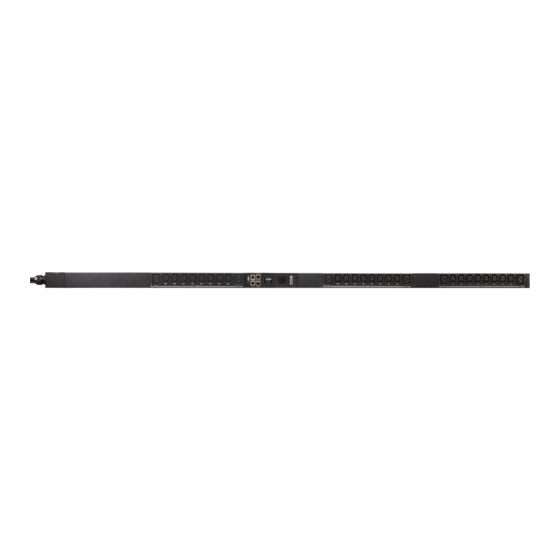
Page 17: Components
PDU PG Series User Manual Components Front View PG98230B / PG98230B2 / PG98230G PG98330B / PG98330B2 PG98330G Item Description power outlets* 30 in total (24 x IEC 60320 C13 + 6 x IEC 60320 C19) Bank 1-1: Outlet 1–10: 8 C13; 2 x C19 Bank 1-2: Outlet 11–20: 8 x C13;... -
Page 18: Status Panel
LEDs These LEDs indicate outlet status. Lights orange for powered on. Off for powered off. Note: Holes for ATEN Lok-U-Plug cable holders are located around the outlets. See Securing the Cables, page 14, for further information. Status Panel Item... - Page 19 PDU PG Series User Manual Item Description readout When PDU / Phase / Bank / Outlet is selected, readouts for its section current, voltage, power, and IP address appear in the display window. Press the button next to the LCD display window to cycle the selection between the items;...
- Page 20 Chapter 1. Introduction This Page Intentionally Left Blank...
-
Page 21: Chapter 2. Hardware Setup
Note: The eco PDU used in the above diagram is only used for reference, it may look different from the PG Series. -
Page 22: Rack Mount Lock Positions
T1: Use T1 to mount the eco PDU onto an ATEN rack with its power cord extending toward the top of the rack. B1: Use B1 to mount the eco PDU onto an ATEN rack with its power cord extending toward the bottom of the rack. -
Page 23: Pdu Placement
PDU PG Series User Manual PDU Placement For safety reasons, the eco PDU shall NOT be installed with the power sockets facing up or down, and thus should only be installed with the power sockets facing out from a vertical position, as shown below: Right. -
Page 24: Installation
5. (Optional) Connect an RS-232/RS-485 serial controller to the unit's COM port. Note: You can also use the port as a PON port, connecting to an ATEN KVM over IP Switch via an Ethernet cable. 6. Connect the unit’s built-in power cord to an AC power source, thereby turning it on, and then turn on the connected devices. -
Page 25: Installation Diagram
PDU PG Series User Manual Installation Diagram Power Temperature Sensor Power RJ-45 RS-232 / 485 Ethernet Hardware / Network Software Controller Power Power... -
Page 26: Securing The Cables
Chapter 2. Hardware Setup Securing the Cables For added safety, use ATEN Lok-U-Plug cable holders to secure the cables of your powered devices in place on the eco PDU. Secure the cable holders using the specially designed holes around the individual power outlets, as shown below: Note: 1. -
Page 27: Chapter 3. Basic Operation And First-Time Setup
ATEN website, along with a separate eco DC user manual. SNMP NRGence eco PDUs support any 3rd-party V1, V2, V3 SNMP manager software. SNMP Management Information Database (MIB) files for the eco PDU device can be found on the software and downloaded from the ATEN website. -
Page 28: First-Time Setup
Address Determination, page 90. After you successfully log in, the eco PDU Energy/Connections page appears. All the screens used in this manual are PE Series based web GUI, PG Series web GUI is identical with different model name printed on the page. -
Page 29: Network Configuration
PDU PG Series User Manual Network Configuration To set up the network, do the following: 3. Click the Setup. The Device Configuration page, similar to the one below, appears. 4. Fill in the fields according to the information provided under Device... -
Page 30: Changing The Administrator Login
Chapter 3. Basic Operation and First-Time Setup Changing the Administrator Login To change the default Administrator username and password, do the following: 1. Click User. Once users have been added to the system, the Accounts page displays a detailed list of users — with more information about them in the large central panel: 2. -
Page 31: Chapter 4. Logging In
2. If a Security Alert dialog box appears, accept the certificate — it can be trusted. The Login page appears. All the screens used in this manual are PE Series based web GUI, PG Series web GUI is identical with different model name printed on the page. -
Page 32: The Eco Pdu Main Page
Chapter 4. Logging In The eco PDU Main Page After you have successfully logged in, the eco PDU main page comes up with the Energy Connections page displayed: Note: The screen depicts an Administrator’s page. Depending on the type of user logged in and its permissions, and your PG model, not all of these elements may appear. -
Page 33: Page Components
Help Connects to the online help section on the ATEN website for the device’s configuration and operation. Logout Click this button to log out of your eco PDU session. - Page 34 Chapter 4. Logging In This Page Intentionally Left Blank...
-
Page 35: Chapter 5. Energy
Chapter 5 Energy Energy Connections When you log in to the eco PDU, the interface opens with its default selection of Energy Connections, with the PDU Status, Sensor Status, Inlet Status, → Bank Status, and Outlet Status sections displayed in the main panel. PDU Status All eco PDU models support PDU device level monitoring. -
Page 36: Sensor Status
Chapter 5. Energy Sensor Status All eco PDU models support sensor monitoring. The Sensor Status section allows you to set up a sensor management configuration for the PDU device: Sensor 1 If you have sensors installed in your installation, use these fields to set the maximum and minimum threshold settings for Temperature, Humidity, and/or Pressure. -
Page 37: Bank Status
PDU PG Series User Manual Bank Status All eco PDU models support Bank level monitoring. The Bank Status section allows you to set up a power management configuration for each of the individual banks (3 banks for PG98230 Series, PG98330B, and PG98330B2; 6... -
Page 38: Outlet Status
Chapter 5. Energy Outlet Status All eco PDU models support Outlet level monitoring. The Outlet Status section allows you to set up a power management configuration for each of the individual outlets: Threshold Settings These fields are used to set the maximum and minimum threshold settings for the Aggregate Current, Voltage, Power, and Power Dissipation. -
Page 39: Configuration
PDU PG Series User Manual Configuration The Configuration page is used to configure the settings of the eco PDU at the bank and individual power outlet level: POP Setting This section allows you to configure the settings for NRGence’s exclusive Proactive Overload Protection (POP) technology. -
Page 40: Bank Configuration
Chapter 5. Energy Bank Configuration Each bank can be given a distinctive name (3 banks for PG98230 Series, PG98330B, and PG98330B2; 6 banks for PG98330G). The maximum number of characters is 15. Bank POP Priority List This field allows you to set up a POP priority list that the eco PDU powers off the outlets according to sequence configured in this list. - Page 41 PDU PG Series User Manual Control/Display Description Confirmation If this option is enabled (there is a check in the checkbox), a dialog Required box comes up asking you to confirm a power operation before it is performed. If it is disabled (there is no check in the checkbox), the operation is performed without confirmation.
- Page 42 Chapter 5. Energy Control/Display Description Remote Turn ON Use the drop-down menu to select one of the choices, below: Method Wake on LAN This is a Safe Shutdown and Restart option. If this is selected, when an Outlet is turned Off, the eco PDU first sends a message to the computer telling it to prepare for a shutdown;...
- Page 43 PDU PG Series User Manual Control/Display Description Auto Ping Auto Ping Method defines the mechanism which the eco PDU uses Method to ping a device and to reboot the outlet. To enable this setting, check the Enable checkbox, or check the Disable checkbox to disable.
- Page 44 Chapter 5. Energy This Page Intentionally Left Blank...
-
Page 45: Chapter 6. User Management
Chapter 6 User Management Overview Selecting the User tab brings up the Accounts menu, with the Administrator Information and User Information displayed in the main panel. Note: There is a pre-installed administrator account. It can be used to set up the device and to begin creating users and groups. -
Page 46: Administrator Information
Chapter 6. User Management Administrator Information This section is used to set the Administrator username and password. Only Administrators can view this section. For details, see Changing the Administrator Login, page 18. SNMPv3 Account Information Enter values for Name, Auth-Password and Priv-Password for SNMPv3 authentication, if required. -
Page 47: User Information
PDU PG Series User Manual User Information To add a user, do the following: 1. Set the Management field to Enable. 2. Key in a name and password in the Name and Password fields. 3. Set the outlet-by-outlet permissions of the user in the Outlet field. - Page 48 Chapter 6. User Management Field Description Save Click this button to save your operation or changes...
-
Page 49: Chapter 7. Log
Chapter 7 The eco PDU keeps a record of all transactions that take place on its installation, and stores up to 1024 events at a any given time. The System Log page provides a powerful array of filters and functions that allow you to view and export the log file data, as well as be informed by email via SNMP Trap / Syslog / SMTP of specified events as they occur. -
Page 50: The System Log Event List
Chapter 7. Log The System Log Event List Clicking on a device in the Sidebar displays its log events in the main panel’s log event list. Clicking the Refresh button updates the log list with the latest events. The entry box to the right of the Refresh button lets you set the number of events displayed per page. -
Page 51: Notification Settings
eco PDU PE Series User Manual Notification Settings The Notification Settings page is used to specify which of the eco PDU’s components will receive notification of a log event. When you click the Notification Settings menu item, a page similar to the one below appears: The event categories are listed in the left column. - Page 52 Chapter 7. Log This Page Intentionally Left Blank...
-
Page 53: Chapter 8 Setup
Chapter 8 Setup Device Management The Setup page allows administrators and users with device management permission to configure and control the overall eco PDU operations. Device Configuration This page presents information about the device selected, as described in the following sections: General... -
Page 54: Service Ports
This item displays the eco PDU’s MAC address. Firmware Version This item displays the current firmware version. You can check if there are any newer versions available on the ATEN website. Rack Location This field lets you give the rack location a unique name for easy Name reference. -
Page 55: Serial Settings
PDU PG Series User Manual Serial Settings In this field, you can configure the console mode and RS-485 serial port address for remote control from the hardware and software controller. IPv4 Configuration The eco PDU’s IPv4 IP and DNS addresses (the traditional method of specifying IP addresses) can either be assigned automatically (DHCP), or manually, by specifying a fix IP address. - Page 56 Chapter 8. Setup For dynamic IP address assignment, select the Obtain IP address automatically radio button. (This is the default setting.) To specify a fixed IP address, select the Set IP address manually radio button and fill in the IP address with values appropriate for your network. For automatic DNS Server address assignment, select the Obtain DNS Server address automatically radio button.
-
Page 57: Ipv6 Configuration
PDU PG Series User Manual IPv6 Configuration The eco PDU’s IPv6 IP and DNS addresses (the traditional method of specifying IP addresses) can either be assigned automatically (DHCP), or manually, by specifying a fix IP address. For dynamic IP address assignment, select the Enable autoconfiguration radio button. -
Page 58: Event Notification
Chapter 8. Setup it hasn’t obtained an IP address after one minute, it automatically reverts to its default IP address (192.168.0.60.) 2. If the device is on a network that uses DHCP to assign network addresses, and you need to ascertain its IP address, see IP Address Determination, page 90. -
Page 59: Snmp Trap Receivers
PDU PG Series User Manual Note: Only one email address is allowed in the From field, and it cannot exceed 64 characters.) 4. (Optional) To enable TLS encryption on your notifications, check the Enable secure connection (STARTTLS) checkbox. We support TLS1.0, TLS1.1, and TLS1.2. -
Page 60: Syslog Server
Chapter 8. Setup 4. Key in the community value(s) if required by the version of SNMP (SNMPv1 and SNMPv2c) used. 5. Key in the auth/privacy password(s) that correspond to each of the stations by the version of SMP (SNMPv3) used. Syslog Server To record all events that take place on the eco PDU devices, and write them to the eco PDU Syslog server, do the following:... -
Page 61: Time Zone
PDU PG Series User Manual Time Zone To establish the time zone that the eco PDU is located in, use the Time Zone drop-down menu to choose the city that most closely corresponds to where it is at. If your country or region employs Daylight Saving Time (Summer Time), check the corresponding checkbox. -
Page 62: Network Time
Chapter 8. Setup Network Time To have the time automatically synchronized to a network time server, do the following: 1. Check the Enable auto adjustment checkbox. 2. Select your preferred time server – or – Check the Preferred custom server IP checkbox, and key in the IP address of the time server of your choice. -
Page 63: Security
PDU PG Series User Manual Security The Security page controls access to the eco PDU. Working Mode If Enable Telnet Server is checked, the eco PDU is accessible via a Telnet sessions using the Telnet username and password (see Telnet, page 25). -
Page 64: Ipinstaller Setting
Chapter 8. Setup IPInstaller Setting If Disable is checked, the IP address of the eco PDU cannot be found by the IP Installer software. If Readonly is checked, the IP address of the eco PDU can be found but not configurable by the IP Installer software. If Read-write is checked, the IP address of the eco PDU can be found and configurable by the IP Installer software. -
Page 65: Ip Filter / Mac Filter
PDU PG Series User Manual Item Description Password Must Contain At Least Checking any of these items requires users to include at least one of the specified items in their password. Note: This policy does not affect existing user accounts. - Page 66 Chapter 8. Setup Adding Filters To add an IP filter, do the following: 1. Click Add. A dialog box similar to the one below appears: 2. Specify the start filter address in the dialog box (for example, 192.168.0.200), then click OK. 3.
-
Page 67: Authentication & Authorization
PDU PG Series User Manual Authentication & Authorization The Authentication & Authorization field is used to set up login authentication and authorization management from external sources. RADIUS Settings To allow authentication and authorization for the eco PDU device through a RADIUS server, do the following: 1. - Page 68 Chapter 8. Setup su/xxxx Where xxxx represents the Username given to the user when the account was created on the eco PDU device. The user’s access rights equivalent to the ones assigned for the eco PDU device. (See Device Management, page 41.) Note: su/user supports view ports only;...
- Page 69 PDU PG Series User Manual 3. In the Timeout field, set the time in seconds that the eco PDU device shall wait for the LDAP server to reply before it times out. The default timeout is 3 seconds. 4. On the LDAP server, set the entry for each user as follows:...
-
Page 70: Private Certificate
For enhanced security, the Private Certificate section allows you to use your own private encryption key and signed certificate, rather than the default ATEN certificate. There are two methods for establishing your private certificate: generating a self-signed certificate or importing a third-party certificate authority (CA) signed certificate. - Page 71 PDU PG Series User Manual Importing the Private Certificate To import the private certificate, do the following: 1. Click Browse to the right of Private Key to locate the location path of the private encryption key file, and select it.
-
Page 72: Wireless Network
Chapter 8. Setup Wireless Network The Wireless Network page allows you to enable the Wi-fi capability of the eco PDU. Wireless Network Item Description Enable Wi-Fi Check to enable the Wi-Fi function on the eco PDU. Scan Once the Wi-Fi adapter is connected to the eco PUD’s USB Type-A port, click Scan to scan for any available wireless network in your area. -
Page 73: Ipv4 Configuration
PDU PG Series User Manual IPv4 Configuration The eco PDU’s IPv4 IP and DNS addresses (the traditional method of specifying IP addresses) can either be assigned automatically (DHCP), or manually, by specifying a fix IP address. For dynamic IP address assignment, select the Obtain IP address automatically radio button. -
Page 74: Ipv6 Configuration
Chapter 8. Setup IPv6 Configuration The eco PDU’s IPv6 IP and DNS addresses (the traditional method of specifying IP addresses) can either be assigned automatically (DHCP), or manually, by specifying a fix IP address. For dynamic IP address assignment, select the Enable autoconfiguration radio button. -
Page 75: Cascade
PDU PG Series User Manual Cascade The Cascade page allows you to manage and cascade eco PDU in your installation. Adding a PDU To add a cascade PDU, do the following: 1. Click Add Device. A dialog box similar to the one below appears: 2. -
Page 76: Connecting A Pdu
Chapter 8. Setup Connecting a PDU To connect to a cascaded PDU, do the following: 1. Check the checkbox(s) beside the ID column of the eco PDU(s) you want to connect. 2. Click Connect. Discovering To discover a cascaded PDU in your installation, do the following: 1. -
Page 77: Rules
PDU PG Series User Manual Rules The Rules page allows you to manage and set rules for the eco PDU in your installation. Item Description Enable Check to enable the rule you configured for your eco PDU. Name This field lets you name the rules. -
Page 78: Scheduler
Chapter 8. Setup Scheduler Use the Scheduler page to power on, power off, or reboot the eco PDU. Creating an Event To create an event, do the following: 1. Go to Setup > Scheduler. 2. Create one or more power-on, power-off, and/or reboot actions. These actions will be selectable when configuring an event. - Page 79 PDU PG Series User Manual 3. Create an event. a) Click +Create Event. b) In the pop-up screen, name the event, and then configure the schedule and action as needed. c) Click Save. The event is added to the event list. Use the toggle button to...
- Page 80 Chapter 8. Setup This Page Intentionally Left Blank...
-
Page 81: Chapter 9 Pdu
The PDU function is used to upgrade the eco PDU’s firmware, and to backup and restore the device’s configuration settings. All the screens used in this manual are PE Series based web GUI, PG Series web GUI is identical with different model name printed on the page. -
Page 82: Firmware File
Chapter 9. PDU Firmware File When you click the Upgrade Main Firmware tab, the display opens with the Firmware file menu page, which looks similar to the one below: A description of the items shown in this panel are given in the table below: Item Description Check Main... - Page 83 PDU PG Series User Manual If you didn't enable Check Main Firmware Version, the upgrade file is installed without comparing. Once the upgrade completes successfully, the switch restarts automatically. 4. Log in again, and check the firmware version to be sure it is the new one.
-
Page 84: Backup/Restore
Chapter 9. PDU Backup/Restore Selecting Backup/Restore on the menu bar gives you the ability to back up the switch’s configuration and user profile information: Station List Station List lists the eco PDU only. Backup To backup the device’s settings, do the following: 1. -
Page 85: Restore
PDU PG Series User Manual Restore To restore a previous backup, do the following: 1. Click Browse, navigate to the file and select it. Note: If you have renamed the file, you can leave the new name as is. - Page 86 Chapter 9. PDU This Page Intentionally Left Blank...
-
Page 87: Chapter 10. Telnet Commands
Chapter 10 Telnet Commands Remote Terminal Operations With ATEN eco PDU you can log in remotely from a computer using Telnet interface that allows system control through a high-end controller or PC. Telnet Telnet is a program that connects to a device over a network to provide text- based management and control. -
Page 88: Session Timeout
PDU PG Series User Manual 1. On your computer, open the start menu and select Run. Type: cmd Click OK. 2. At the command prompt, key in telnet and the IP Address of the PDU, as follows: telnet [IP Address] 3. -
Page 89: Commands
Chapter 10. Telnet Commands Commands Use the Telnet commands to view and configure the eco PDU as described in each section. The text-based command line provides some of the same functions found under the Energy tab of the eco PDU’s web-based GUI. Commands to view and configure the eco PDU are provide in the following sections. -
Page 90: Read Power Outlet Status
PDU PG Series User Manual Read Outlet Status Power The Read Power Outlet Status command allows you to view the power status of an outlet on the eco PDU. The formula for Read Outlet Status commands is as follows: Command + Outlet + Number + Option + [Enter] 1. -
Page 91: Switch Outlet Status
Chapter 10. Telnet Commands Switch Outlet Status The Switch Outlet Status command allows you to change the power status of an outlet on the eco PDU. The formula for Switch Outlet Status commands is as follows: Command + Outlet + Number + Option + Control + [Enter] 1. - Page 92 PDU PG Series User Manual The following table lists the available Switch Outlet Status commands: Command Outlet Option Control Enter Description imme [Enter] Switch outlet XX on with option imme or delay. XX: delay Outlet number (01 ~ 04)
-
Page 93: Read Environmental Value
Chapter 10. Telnet Commands Read Environmental Value The Read Environmental Value command allows you to view measurements from the eco PDU’s environmental sensors. The formula for Read Environmental Value commands is as follows: Command + Outlet + Number + Option + [Enter] 1. -
Page 94: Close Telnet Session
PDU PG Series User Manual The following table lists the available Read Environmental Value commands: Command Sensor Option Enter Description read sensor simple [Enter] Read the environmental sensor value on the selected power outlet with format environmental sensor installed. Outlet XX with option simple or format. -
Page 95: Reboot Pdu Device
Chapter 10. Telnet Commands Reboot PDU Device The Reboot PDU Device command allows you to reboot the eco PDU. The formula for Reboot PDU Device commands is as follows: Command + [Enter] 1. For example, if you want to reboot the eco PDU, type the following: reboot [Enter] The following tables show the possible values for the Read Environmental Value commands:... - Page 96 PDU PG Series User Manual The following table lists the available Reset All PDU Config to Default Value command: Command Enter Description eco PDU clearallsetting [Enter] Resets the to default factory settings.
-
Page 97: Appendix
Appendix Safety Instructions General This product is for indoor use only. Read all of these instructions. Save them for future reference. Follow all warnings and instructions marked on the device. Do not place the device on any unstable surface (cart, stand, table, etc.). If the device falls, serious damage will result. - Page 98 Appendix Do not allow anything to rest on the power cord or cables. Route the power cord and cables so that they cannot be stepped on or tripped over. To help protect your system from sudden, transient increases and decreases in electrical power, use a surge suppressor, line conditioner, or uninterruptible power supply (UPS).
-
Page 99: Rack Mounting
To secure the cables in the eco PDU’s power outlets, use only the ATEN Lock-Your-Plug cable holders that have been specifically designed to work with the eco PDU. Using any other kind of cable securing device could be highly dangerous. Please contact your ATEN dealer for information about ATEN Lock-Your-Plugs. -
Page 100: Resetting The Circuit Breaker
Appendix Resetting the Circuit Breaker Before switching the circuit breaker to reset a trip, power down and disconnect all devices connected to the eco PDU's power outlets to prevent damage caused by a sudden power surge. If a power surge causes the eco PDU’s circuit breaker to switch off the power and it needs to be reset, follow the instructions below. -
Page 101: Technical Support
PDU PG Series User Manual Technical Support International For online technical support – including troubleshooting, documentation, and software updates: http://eservice.aten.com For telephone support, see Telephone Support on page viii. North America Email Support support@aten-usa.com Online Troubleshooting http://www.aten-usa.com/support Technical Documentation... -
Page 102: Ip Address Determination
Appendix IP Address Determination If you are an administrator logging in for the first time, you need to access the eco PDU in order to give it an IP address that users can connect to. There are two methods to choose from. In each case, your client computer must be on the same network segment as the eco PDU. -
Page 103: Method 2
NRGence eco DC allows you to determine/assign an IP address in order to configure a PDU device and monitor power status of the equipment connected to it. NRGence eco DC can be obtained from the Download area of the ATEN web site. -
Page 104: Specifications
Appendix Specifications PG98230B / PG98230B2 / PG98230G Function PG98230B PG98230B2 PG98230G Electrical Nominal Input 208V 3PH (Delta) 400/230V 3PH (Star) Voltage Maximum Input 16A (Max) 20A (Max) ; Current 16A (UL de-rated) Input 50 - 60 Hz Frequency Input NEMA L21-20P NEMA L15-20P IEC 309 16/20A Red 3P+N+PE Connection... -
Page 105: Pg98330B / Pg98330B2 / Pg98330G
PDU PG Series User Manual Compliance CE, EMC Verification Safety UL, PSE Verification Warranty 3 Years PG98330B / PG98330B2 / PG98330G Function PG98330B PG98330B2 PG98330G Electrical Nominal Input 208V 3PH (Delta) 400/230V 3PH (Star) Voltage Maximum Input 32A (Max) 30A (Max) ;... - Page 106 Appendix 0 – 80 % RH, Non-Condensing Humidity (Operating & Storage) Compliance CE, EMC Verification Safety UL, PSE Verification Warranty 3 Years...
-
Page 107: Administrator Login Failure
PDU PG Series User Manual Administrator Login Failure If you are unable to perform an Administrator login (because the Username and Password information has become corrupted, or you have forgotten it, for example), you can clear the login information with the following procedure: 1. -
Page 108: Limited Warranty
Copyright © 2022 ATEN® International Co., Ltd. Released: 2022-09-08 ATEN and the ATEN logo are registered trademarks of ATEN International Co., Ltd. All rights reserved. All other brand names and trademarks are the registered property of their respective owners.