Advertisement
SPECIFICATIONS
Radio section
Tuning system:
PLL Frequeency synthesizer sys-
tem
Receive range:
FM
MW
LW
Intermediate frequency:
FM
MW
LW
FM Separation:
Quieting sensitivity:
FM
PS-3025K-A;
MW
LW
PS-3025K-B;
MW
LW
Auto tuning stop sensitivity:
FM
PS-3025K-A;
MW
LW
Clarion Co., Ltd.
7-2, Shintoshin, Chuo-ku, Saitama-shi, Saitama 330-0081 Japan
Service Dept.: 7-2, Shintoshin, Chuo-ku, Saitama-shi, Saitama 330-0081 Japan
Tel: +81-48-601-3705 FAX: +81-48-601-3804
87.5MHz to 108.0MHz
531kHz to 1602kHz
153kHz to 279kHz
10.7 +0.2/-0.2MHz
1st 10.71 +0.2/-0.2MHz
2nd 450 +3/-3kHz
1st 10.71 +0.03/-0.03MHz
2nd 450 +3/-3kHz
22 +5/-7dB
Less than 15dBu
(at 30dB S/N)
Less than 34dBu
(at 20dB S/N)
Less than 40dBu
(at 20dB S/N)
Less than 39dBu
(at 20dB S/N)
Less than 45dBu
(at 20dB S/N)
22 +6/-6dBu
32 +6/-6dBu
32 +6/-6dBu
- 1 -
Service Manual
SUZUKI Automobile Genuine
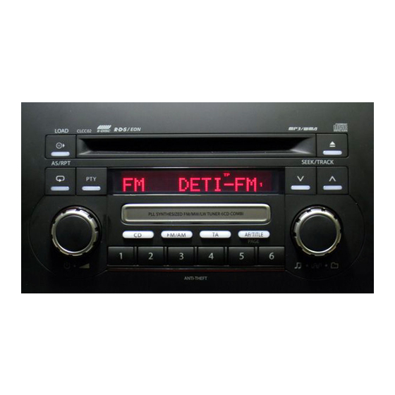
RDS/FM/MW/LW TUNER CD
COMBI
PS-3025K-A
Model
(Genuine No.39101-80JA1-CZT)
(ID No.CLCC02)
PS-3025K-B
Model
(Genuine No.39101-80JB1-CZT)
(ID No.CLCC02)
CD section
Disc:
Separation:
S/N ratio:
Distortion:
MP3/WMA section
MP3 sampling rate:
MP3 bit rate:
WMA bit rate:
Logical format:
General
Rated Voltage :
Quiting Output:
Back-up consumption: Less than 5mA
Dimensions(mm):
Weight:
*
Please measure it auto loud function off.The auto loud
function off by pushed 1ch,2ch and the up button.
Published by Service Dept.
298-6536-00 Jan.2008
Printed in Japan
PS-3025K-B;
MW
42 +6/-6dBu
LW
42 +6/-6dBu
12cm Disc
More than 55dB
More than 70dB(JIS-A)
Less than 0.3%(20kHz-LPF)
11.025kHz to 48kHz
8kbps to 320kbps/VBR
48kbps to 192kbps
ISO9660 level 1,2
JOLIET or Romeo
DC 13.2V
More Than 12Wx4 (10% Dist.)
More Than 16Wx4 (Max Output)
248.4(W)x141.5(H)x176.9(D)
approx.1.8kg
PS-3025K-A,B
Advertisement
Table of Contents

Related Manuals for Clarion PS-3025K-A


Summary of Contents for Clarion PS-3025K-A
-
Page 1: Service Manual
Clarion Co., Ltd. Published by Service Dept. 7-2, Shintoshin, Chuo-ku, Saitama-shi, Saitama 330-0081 Japan 298-6536-00 Jan.2008 Service Dept.: 7-2, Shintoshin, Chuo-ku, Saitama-shi, Saitama 330-0081 Japan Printed in Japan Tel: +81-48-601-3705 FAX: +81-48-601-3804 Service Manual SUZUKI Automobile Genuine RDS/FM/MW/LW TUNER CD... -
Page 2: Computer Anti-Theft System
Please do not heat the chip capacitors with a soldering iron COMPONENTS directly. 7. Cautions in handling for chip parts. PS-3025K-A,B Do not reuse removed chips even when no abnormality is ob- Main unit --------------- served in their appearance. Always replace them with new ones. - Page 3 46: EEP CK : O : EEP-ROM clock pulse out. 8: ANT-ON / TP : O : Antenna-ON signal output, and the test pin 47: EEP CS : O : EEP-ROM chip select signal out. signal output. - 3 - PS-3025K-A,B...
- Page 4 : IN : Volume control pulse input from the rota- ry encoder. SEL 2 ( pin 84 ) pin 75: VOL 2 R : IN : Volume control pulse input from the rota- SEL 3 ( pin 84 ) ry encoder. PS-3025K-A,B - 4 -...
-
Page 5: Block Diagram
VDD+3.3V BUFFER /AUX-L/R IC351 NJM4558V S-GND Improvement feature Do not hear it easily because of the running car noise, and it responds at the speed of the car and it changes low and high frequeency gain. - 5 - PS-3025K-A,B... -
Page 6: Exploded View Parts List
310-1826-10 UPPER CASE 074-1194-00 OUTLET SOCKET 286-6186-19 SETPLATE 074-1302-08 OUTLET SOCKET 313-1962-00 HEAT SINK 074-4007-20 OUTLET SOCKET 714-2606-8B MACHINE SCREW(M2.6x6) 092-0702-00 ANT-RECEPT 331-4193-20 SU-PLATE 941-0215-80 TUNER PACK 714-2610-89 MACHINE SCREW(M2.6x10) --------------- Main PWB 716-0878-50 IT SCREW(M2.6x5) 778-3006-00 TAP-SCREW(3x6) PS-3025K-A,B - 6 -... - Page 7 335-7705-00 LCD HOLDER 345-5590-00 RUBBER SW (LEFT) 335-7929-00 COLOR FILTER 345-5591-00 RUBBER SW (RIGHT) 001-7048-91 DIODE RED 001-7087-90 DIODE RED --------------- Switch PWB 017-0420-43 PILOT LAMP (14V 40mA RED) 016-0014-12 VR W/SHAFT 074-3013-74 OUTLETSOCKET 345-6006-00 PROTECTOR - 7 - PS-3025K-A,B...
-
Page 8: Electrical Parts List
ANT101 092-0702-00 ANT-RECEPT C353 042-1562-15 10V 220uF D152 001-0580-90 1SS352 BL101 941-0215-80 TUNER PACK C354 166-2201-50 22pF CH D391 001-0580-90 1SS352 (PS-3025K-A) C355 166-2201-50 22pF CH 941-0221-80 TUNER PACK D504 001-0580-90 1SS352 C356 166-1007-50 10pF CH D505 (PS-3025K-B) C357 166-1007-50 10pF CH... - Page 9 032-0140-50 1/10W 10k ohm F R391 119-5631-15 1/10W 56k ohm R573 119-4731-15 1/10W 47k ohm R111 119-0000-05 1/10W 0 ohm JW (PS-3025K-A) R392 119-1221-15 1/10W 1.2k ohm R576 119-0000-05 1/10W 0 ohm JW R701 116-1211-15 1/4W 120 ohm 166-8201-50 82pF CH R393 119-2221-15 1/10W 2.2k ohm...
- Page 10 R107 119-1221-15 1/10W 1.2k ohm VR101 016-0014-12 VR W/SHAFT R108 119-1221-15 1/10W 1.2k ohm 039-3035-00 PWB(WITHOUT D113 001-0580-90 1SS352 R109 119-1521-15 1/10W 1.5k ohm COMPONENT) D114 001-0580-90 1SS352 R110 119-1221-15 1/10W 1.2k ohm D115 001-0580-90 1SS352 PS-3025K-A,B - 10 -...
-
Page 11: Circuit Diagram
2.5V RDS-DCHG RDS-DCHG RDS-CLK RDS-CLK RDS-DATA RDS-DATA RDS-MUTE RDS-MUTE S-METER 10 11 12 10 11 13 14 15 16 SD-S-UP SPEED-UP X121 SD-CONT 7.2MHz SD-CONT SD/ST SD/ST PLL-CE L121 22uH PLL-DO PLL-CL PLL-DI U-GND(1) SYS+5V(1) R128 PS-3025K-A,B - 11 -... - Page 12 To Main PWB 4/4 Page 14 NOISE-IN 5.2V RDS-DCHG SYS+5V(5) B/U(4) RDS-CLK RDS-DATA ACC(4) RDS-MUTE ILL+13V ILL(+) S-METER ILL(-) SPEED-UP IC502 SD-CONT NJM2103M Q504 Q505 PLL-CE R540 C4155 C4155 PLL-DO R549 330K R555 PLL-CL 5.6K PLL-DI U-GND(1) 5.2V SYS+5V(1) - 12 - PS-3025K-A,B...
- Page 13 10 16V 10K 1% AMP-MUTE VOL-DATA To Main PWB 4/4 R354 10K1% TEL/AUX-L Page 14 R397 TEL/AUX-L AMP-ON AMP-MUTE R355 C356 10K 1% TEL/AUX-R AMP-ON TEL/AUX-G BEEP R360 C354 C361 10K 1% 10 16V U-GND(2) SYS+5V(2) - 13 - PS-3025K-A,B...
- Page 14 R-CH INPUT(-) AUX R-CH (+) L(+) 2.5V 3.8V R904 0 TEL/AUX-R 9 SYS-ACC TEL/AUX-R used K-B 10 BUS (-) TEL/AUX-G TEL/AUX-G R905 0 11 L-CH INPUT(-) used K-B ILLUMINATION (+) R908 0 J701 used K-A N.C. 074-1194-00 - 14 - PS-3025K-A,B...
-
Page 15: Printed Wiring Board
Caution: P501 COMPONENT SIDE: Parts on the component side seen TM502 from the component side are indicated. Flat wire (816-4024-50) COMPONENT SIDE To J100 of Switch PWB To J1 of CD Mechnism Page M14 Page 18 PS-3025K-A,B - 15 -... -
Page 16: Solder Side
10 BUS (-) J801 J701 11 L-CH INPUT(-) ANT101 IC391 ILLUMINATION (+) N.C. J721 2 3 4 TM801 CATS TP SOLDER SIDE Caution: SOLDER SIDE: Parts on the solder side seen from the solder side are indicated. - 16 - PS-3025K-A,B... - Page 17 COMMK C100 CD-LOAD FM/AM 1.6V C101 3.2V C102 4.7V C103 VLCD2 5.2V 10 11 12 13 14 15 16 17 18 19 20 21 22 23 24 R200 180K L100 22uF R201 180K R202 180K R203 180K - 17- PS-3025K-A,B...
- Page 18 Caution: COMPONENT SIDE: Parts on the component side seen from the component side are indicated. SOLDER SIDE: Parts on the solder side seen from the solder side are indicated. PL109 PL110 PL111 VR100 POWER/VOL CD-LOAD AS/RPT - 18 - PS-3025K-A,B...
- Page 19 Clarion Co., Ltd. Published by Service Dept. 7-2, Shintoshin, Chuo-ku, Saitama-shi, Saitama 330-0081 Japan Nov.2007 Service Dept.: 7-2, Shintoshin, Chuo-ku, Saitama-shi, Saitama 330-0081 Japan Printed in Japan Tel: +81-48-601-3705 FAX: +81-48-601-3804 Service Manual In Dash 6disc CD Auto Changer Mechanism(GI-X)
- Page 20 pin 81: TEST 3 : IN : For the test. pin 91: VSS : - : Negative voltage supply. pin 82: TEST 4 : IN : For the test. pin 92: SW 3 : IN : The switch signal input. pin 83: REQ O : O : Transmit request signal output.
- Page 21 How to remove "DRIVE UNIT" How to remove "LO-MOTOR-S-ASSY" 1. Remove the screw and DRIVE SPRING-A. 1. Remove two screws and DRIVE CHASSIS-B. 2. Rotate DRIVE UNIT internally. 2. Remove the screw of the bottom side. 3. Remove the washer, and remove DRIVE UNIT. 3.
-
Page 22: Operation
OPERATION Discholder MOT2 (Mode Motor) S1 of CD-PWB (Mode Plate) S2 of CD-PWB (Mode Plate) Drive Unit S3 of CD-PWB (Mode Plate) MOT3 (UP/DW-Motor) S5 of SENSOR-U-FPC (Sutter) MOT1 (Loading Motor) S4 of CD-PWB (Holder) Loading Roller Shutter PT3 of SENSOR-L-FPC PT2 of SENSOR-L-FPC PT1 of SENSOR-L-FPC IC10 of CD PWB... - Page 23 EXPLODED VIEW/PARTS LIST Main section to C2 to C4 to C3 to D3 to B1 to B2 to C1 to A6 to A7 33 34 to A3 to A5 to A2 to A4 to D3 21 14 * Do not reuse the following parts. (No.24,25,28,29,30,31,32) PART NO.
- Page 24 Lower unit assy section : 966-1864-20 to A1 to A2 to A3 to A5 to A7 to A6 PART NO. DESCRIPTION Q'TY PART NO. DESCRIPTION Q'TY 966-1757-25 LOWER-C-ASSY 620-1623-24 CAM GEAR 966-0658-22 DH-SP-ASSY A 620-1624-24 GEAR COVER 966-1758-20 DS-SP-ASSY A 621-0732-21 M-GEAR B 966-0660-22 DH-SP-ASSY S 621-0733-20 M-GEAR C...
- Page 25 [ Grease Point ] * Grease: SANKOL FG-87HSR Put grease on the surface Put grease on the reverse side Put grease on the both sides Put grease on the edge - M7 - 929-0374-81...
- Page 26 S-Drive-CH unit section : 966-1753-22 to A2 to A1 to B1 to A3 to A4 * Do not reuse the following parts. (No.17,18,19,20) PART NO. DESCRIPTION Q'TY PART NO. DESCRIPTION Q'TY HBS-565-200 N-DRIVE UNIT 716-3450-00 SCREW(M1.7x2.0) HBS-567-200 LOADING-U-ASSY 716-3459-01 SCREW(M1.7x2.0) HBS-556-100 LO-MOTOR-S-ASSY 750-6761-20 DRIVE SPRING A HBS-552-200 L-SENSOR-S-ASSY...
- Page 27 [ Grease Point ] * Grease A: SANKOL FG-87HSR * Grease B: SANKOL CFD-006MBL Put grease on the surface Put grease on the reverse side Put grease on the both sides Put grease on the edge Surface of PIN Surface of Spring - M9 - 929-0374-81...
- Page 28 Upper unit assy section : 966-1764-21 to A1 * Do not reuse the following parts. (No.7,8,10) PART NO. DESCRIPTION Q'TY to A2 966-1761-21 UPPER-CHA-ASSY 966-1765-20 LO-SHIFT A ASSY 966-0700-22 LO-SHIFT B ASSY 966-0701-21 LO-SHIFT ASSY 966-1766-20 SHUTTER-PL-ASSY 966-1763-20 SHUTTER ASSY HBS-553-200 U-SENSOR-S-ASSY ----------- SENSOR-U-FPC...
- Page 29 ELECTRICAL PARTS LIST CD PWB(BM1) section REF No. PART No. DESCRIPTION REF No. PART No. DESCRIPTION REF No. PART No. DESCRIPTION 042-0672-00 25V 47uF TA 042-0672-00 25V 47uF TA 168-1042-78 16V 0.1uF 119-4731-15 1/10W 47k ohm 166-1011-50 100pF CH 166-1011-50 100pF CH 168-2222-55 2200pF K 119-2231-15 1/10W 22k ohm 168-1042-78 16V 0.1uF...
- Page 30 BLOCK DIAGRAM - M12- 929-0374-81...
-
Page 31: Circuit Diagram
CIRCUIT DIAGRAM CD PWB(BM1) section Sensor-L-FPC(BM2) section Sensor-U-FPC(BM3) section 2SB1427 2SB1427 3.3V CD3.3 074-1237-69 9.0V CD-9V CD-9V 47 10V TAN 3.3V 16.92M 3.3V 3.3V SYS-ACC 3.3V TP14 0.047 470p 2SB1188 3.3V 2SB1188 Drive Unit MOT3 3.3V UP/DOWN 6800p 3.0V (V-MOTOR) N.C. - Page 32 PRINTED WIRING BOARD CD PWB(BM1) section Sensor-L-FPC(BM2) section Sensor-U-FPC(BM3) section Drive Unit MOT3 Up/Dw To Main PWB CD PWB(BM1) section CD PWB(BM1) section SOLDER SIDE COMPONENT SIDE MOT1 Loading Sensor-L-FPC(BM2) section MOT2 Mode Sensor-U-FPC(BM3) section LED1 Caution: COMPONENT SIDE: Parts on the component side seen from the component side are indicated.