Advertisement
ORIGINAL SERVICE MANUAL
This additional service manual is designed to be used to-
gether with the original manual.
Original model
PH-2761C-F
PH-2761C-A
PH-2761C-G
PH-2761C-B
PH-2761C-H
PH-2761C-C
PH-2761C-I
PH-2761C-D
PH-2761C-J
PH-2761C-E
PH-2761C-K
PH-2761C-D
Clarion Co., Ltd.
50 Kamitoda, Toda-shi, Saitama 335-8511 Japan
Service Dept.: 5-66 Azuma , Kitamoto-shi, Saitama 364-0007 Japan
Tel: +81-48-541-2335 / 2432 FAX: +81-48-541-2703
PH-2761C-F
Manual No.
298-6303-00
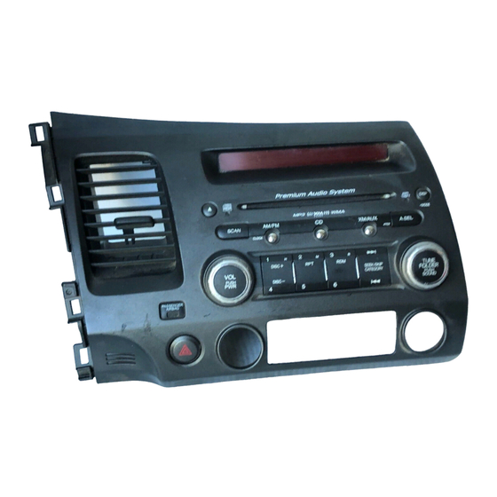
Service Manual
HONDA Automobile Genuine
AM/FM Radio CD Stereo
(Pre-AMP Type)
PH-2761C-F
Model
( Genuine No. 39100-SVA-A11 )
( ID No. 4PC0 / ID Label: HM-B )
PH-2761C-G
Model
( Genuine No. 39100-SVA-A11 )
( ID No. 4PC0 / ID Label: HM-H )
PH-2761C-H
Model
( Genuine No. 39100-SVA-C11 )
( ID No. 4PC1 / ID Label: HN-B )
PH-2761C-I
Model
( Genuine No. 39100-SVB-A11 )
( ID No. 4TC0 / ID Label: HP )
PH-2761C-J
Model
( Genuine No. 39100-SVB-C11)
( ID No. 4TC1 / ID Label: HQ )
PH-2761C-K
Model
( Genuine No. 39100-SNA-K51 )
( ID No. 4TC6 / ID Label: TL-B )
DIFFERENT POINT
CD mechanism and some parts were changed from the
original model(PH-2761C-A/B/C/D/E).
CD mechanism 929-0292-80
- 1 -
Published by Service Dept.
298-6423-00 Jan.2007
Printed in Japan
PH-2761C-A/B/C/D/E PH-2761C-F/G/H/I/J/K
929-5000-80
PH-2761C
Advertisement
Table of Contents

Related Manuals for Clarion PH-2761C-F


Summary of Contents for Clarion PH-2761C-F
- Page 1 Clarion Co., Ltd. Published by Service Dept. 50 Kamitoda, Toda-shi, Saitama 335-8511 Japan 298-6423-00 Jan.2007 Service Dept.: 5-66 Azuma , Kitamoto-shi, Saitama 364-0007 Japan Printed in Japan Tel: +81-48-541-2335 / 2432 FAX: +81-48-541-2703 Service Manual HONDA Automobile Genuine AM/FM Radio CD Stereo...
-
Page 2: To Engineers In Charge Of Repair Or Inspection Of Our Products
To engineers in charge of repair or The laser is focused on the disc reflection surface through the inspection of our products. lens of the optical pickup. When checking that the laser opti- Before repair or inspection, make sure to follow the cal diode lights up, keep your eyes more than 30cms away from the lens. - Page 3 EXPLANATION OF IC pin 57: EJECT SW : IN : Eject switch signal input. 052-3197-21 uPD703272YGC324-8EAA System Contoller pin 58: SBSY : IN : Sub code block synchronous signal detec- tion input. Terminal Description pin 59: LD MUTE : O : Muting signal output to the CD mecha- 1: A Vref 0 : - : Reference voltage for the internal ADC.
-
Page 4: Exploded View Parts List
286-6685-13 SETPLATE (PH2761CG) 286-6685-14 SETPLATE (PH2761CH) 286-6685-17 SETPLATE (PH2761CI) 286-6685-18 SETPLATE (PH2761CJ) 286-6685-28 SETPLATE (PH2761CK) ----------- SOCKET CVR(Unused) 074-1237-79 OUTLET SOCKET(MECH) NOTE) ES color code LCD color PH-2761C-F(M-B) NH608L BLUE PH-2761C-G(HM-H) YR334L BLUE PH-2761C-H(HN-B) NH608L BLUE PH-2761C-I(HP) NH608L AMBER PH-2761C-J(HQ) - Page 5 ELECTRICAL PARTS LIST CIRCUIT DIAGRAM Main PWB section(B1) : Changed point * Other parts are the same as the original model. Please refer to page 14 of the original service manual. * Please refer to ELECTRICAL PARTS LIST about the changed parts. * Other circuits are the same as the original model.
- Page 6 PRINTED WIRING BOARD Main PWB section(B1) 1/2 Caution: COMPONENT SIDE: Parts on the component side seen from the component side are indicated. SOLDER SIDE: Parts on the solder side seen from the solder side are indicated. D503 D504 10 12 14 9 11 13 Q101 Q301...
- Page 7 AUX SIG GND SW +B BUS GND MAIN GND SECURITY (TELM SH GND) Main PWB section(B1) 2/2 NC(TELM SIG-) AUX DET GND-SHIELD (NAVI SH GND) NC(HFT ICON1) NC(NAVI GND) AUX R-CH SYSTEM ACC ILL-C REMOTE NC(HFT MUTE) AUX L-CH REMOTE GND NC(TELM SIG+) NC(NAVI R-CH) BUS+...
- Page 8 Switch PWB-A(B2) section Switch PWB-B(B2) section Flat wire (816-4013-51) To J202 of SW PWB-B To J205 of SW PWB-A To P701 of Main PWB (page 7) To J204 of SW PWB-A Flat wire (816-4014-51) To J203 of SW PWB-B COMPONENT SIDE SOLDER SIDE Switch PWB-B(B2) COMPONENT SIDE...
-
Page 9: Block Diagram
Clarion Co., Ltd. Published by Service Dept. 50 Kamitoda, Toda-shi, Saitama 335-8511 Japan Service Dept.: 5-66 Azuma , Kitamoto-shi, Saitama 364-0007 Japan Printed in Japan Tel: +81-48-541-2335 / 2432 FAX: +81-48-541-2703 Service Manual CD mechanism 929-5000-80 Model BLOCK DIAGRAM PICK UP UNIT... - Page 10 EXPLODED VIEW / PARTS LIST 929-5000-80 - M2 -...
- Page 11 PART NO. DESCRIPTION Q'TY PART NO. DESCRIPTION Q'TY ----------- SENSOR PWB 621-1750-20 POWER GEAR C ----------- MAIN PWB 621-1751-20 POWER GEAR D SMA-182-100 SPINDLE MOTOR-ASSY 621-1752-20 DISC STOPPER SMA-183-100 SLED MOTOR-ASSY 621-1753-20 CLAMPER RING 345-5476-20 CUSHION RUBBER 621-1754-20 GEAR BASE 620-1023-23 CLAMPER PLATE 622-1571-21 ROLLER SHAFT 620-1026-21 SPRING PLATE...
-
Page 12: Electrical Parts List
ELECTRICAL PARTS LIST CD PWB(BM1) section REF No. PART No. DESCRIPTION REF No. PART No. DESCRIPTION REF No. PART No. DESCRIPTION 168-1042-78 16V 0.1uF 046-3332-78 0.033uF 117-1001-15 1/8W 10 ohm 163-1073-35 16V 100uF 046-6822-58 6800pF 033-2211-15 1/10W 220 ohm 178-1052-78 1uF 168-1042-78 16V 0.1uF 033-0000-05 1/10W 0 ohm 042-0560-85 6.3V 100uF... -
Page 13: Circuit Diagram
CIRCUIT DIAGRAM CD PWB(BM1) section Sensor PWB(BM2) section To pick up PS1192HB PS1192HB SENSOR-A BA5830FP 4.0V 3.6V VO3+ VO2+ 4.0V 3.8V VO3- AN1105W-RR VO2- 3.6V VO4+ 3.8V VO1+ 4.0V 3.8V VO4- PwVCC2 PwVCC PwGND PwGND 0/IF-VDD 3.3V MUTE 2SB1188 0/IF-VDD LDIN PrGND 1.8V... -
Page 14: Printed Wiring Board
PRINTED WIRING BOARD CD PWB(BM1) section Sensor PWB(BM2) section CD PWB (BM1) COMPONENT SIDE IC Q SPINDLE MOTOR-ASSY With LEAD (SMA-182-100) SLED MOTOR-ASSY (SMA-183-100) Sensor PWB-B (BM2) MARKING Sensor PWB-A (BM2) PICK UP-ASSY (969-0071-30) FLAT WIRE (816-2542-01) Caution: COMPONENT SIDE: Parts on the component side seen from the component side are indicated.