Advertisement
Quick Links
Advertisement

Related Manuals for Blaupunkt TravelPilot RGS 05


Summary of Contents for Blaupunkt TravelPilot RGS 05
- Page 1 Fitting instructions Page 21 - 39 TravelPilot RGS 05 5" TFT Display 8 622 401 120 7 612 001 219...
- Page 2 Magnetic field sensor (electronic compass) Safety instructions Note: You must determine the optimum mounting location for the magnetic field sensor in each vehicle individually. Before permanently Installation and connection regulations installing the magnetic field sensor, attach it temporarily and then test While installing and mounting this equipment, you must the chosen location with the installation and calibration CD-ROM to disconnect the negative terminal of the battery.
- Page 3 Wheel sensors and magnetic strips Fig. 4 Seen from the driving direction, the antenna is to be mounted on the right- hand side in the rear of the vehicle (passenger’s side, in Great Britain, driver’s side). On notchback vehicles, mount the antenna on the lid of the Safety instructions boot using the corner clamps, Fig.
- Page 4 Removing the display, fig. 16 1. Unscrew four screws on the rear side of the display and remove the back plate. 2. Carefully pull off the connector and push through the ball-and-socket base. 3. Then mount the desired holder. Subject to modifications! Componentry Fig.
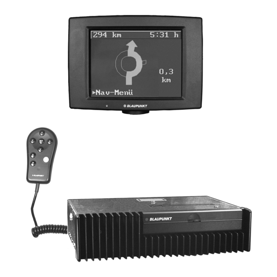
- Page 5 Componentry Fig. 1 GPS receiver GPS antenna Precision resistor Magnetic field sensor - 24 -...
- Page 6 Componentry Fig. 1 Wheel sensors (2x) Wheel sensor extension cord (2x) Loudspeaker Display - 25 -...
-
Page 7: Mounting Material
Mounting material Positive-negative connection Fig. 2 UBatt Ignition ground terminal 30 terminal 15 brown black - 26 -... - Page 8 Precision resistor connection Fig. 3 Connection block for the navigation unit Heckscheibe Rear window Chassis measuring wire 50 cm 75 cm precision resistor Mounting the wheel sensor and magnetic strip Fig. 4 max. 25 mm cut edge rim edge magnetic strips - 27 -...
- Page 9 Installation tolerances for the wheel sensors Fig. 5 Z = 6,5 ± 1,5 mm (steel rim) Clearance Z: Z = 5 - 0/+ 1 mm (alu rim) referred to the centre of the wheel sensor. centre of the sensor Offset Y: The centre of the sensor must be located over the entire circumference of the wheel over the magnetic strip.
- Page 10 Fig. 6 Fig. 7 Fig. 8 loop loop Fig. 9 Fig. 10 - 29 -...
- Page 12 Mounting the Display +12V Fig. 12 Fig. 13 Fig. 14 - 31 -...
- Page 13 Fig. 15 Fig. 16 - 32 -...
-
Page 14: Error Message List
Error message list Service Checklist The following error messages can appear in the top line on the Check the following points during servicing! screen in any menu regardless of what function is currently being performed. 1) Is the operating power supply all right? „Check r. - Page 15 Error: Frequent loss of locating with message faulty „left“ or „right wheel sensor“ Load the installation disk Select „wheel sensor test“ and drive straight on. Are the impulses for wheel 1 and 2 the same? Is the difference between the counters practically „zero“? Are the magnetic strips damaged? Run „sensor - emulator test“...
- Page 16 Error: Locating loss when the rear window defogger is switched on and the magnetic field sensor has been mounted on the rear window - Load the installation disk. - Select the hardware test „wiring test“. - Switch on the rear window defogger. The indication for „precision resistor“...
- Page 17 Error: Regular locating loss even after a short drive Load the installation disk. Select „find compass location“, then select „compass ellipse“. Drive the vehicle in a circle. Is there an ellipse visible on the screen inside the squares? Replace the magnetic field sensor. Run the „sensor - emulator test“...
- Page 18 Error: Regular locating loss due to wheel magnetism Jack up the vehicle. Load the installation disk. Select „find compass location“, then select „compass error“. Press „reset“. Turn each wheel. The value indicated for „Loc. error“ must be less than „3.5“. Demagnetise the wheel and repeat the test.
- Page 19 Error: Occasional locating loss due to electrical equipment in the vehicle Load the installation disk. Select „find compass location“ and then select „compass error“. Press „reset“. Switch on each piece of electrical equipment individually. The value indicated for „Loc. error“ must be less than „3.5“. Check logical equipment combinations as well.
- Page 20 Error: No GPS satellite reception for several days Load the installation disk. Select „GPS status display“. „No GPS communication available“ will appear on the display. Connect a test GPS antenna. Find a clear area and switch the navigation system on. After approximately 1 minute GPS communication should be possible.