Table of Contents
Advertisement
Model
5900830
5900937
5900951
5901023
5900582
5900601
5901021
5900504
5900583
5900585
5900505
This manual is available in Spanish. For a copy, contact your Snapper Pro dealer or www.snapperpro.com.
Este manual está disponible en Español. Para obtener una copia, póngase en contacto con su distribuidor
Operator ' s Manual
Description
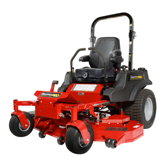
S200XTBV2861, 61" Cut Zero-Turn Riding Mower
S200XTKAV2661, 61" Cut Zero-Turn Riding Mower
S200XTBV3261, 61" Cut Zero-Turn Riding Mower
S200XTB2861, 61" Cut Zero-Turn Riding Mower
S200XTB3061, 61" Cut Zero-Turn Riding Mower
S200XTBV3661, 61" Cut Zero-Turn Riding Mower
S200XTKAV2661, 61" Cut Zero-Turn Riding Mower
S200XTBV32, Zero-Turn Riding Mower
S200XTB30, Zero-Turn Riding Mower
S200XTBV36, Zero-Turn Riding Mower
S200XT/72", 72" Cut Mower Deck
Snapper Pro o www.snapperpro.com.
S200XT Series
Ze ro -Tu r n R i d i n g M owe r s
5102188
Revision: J
Advertisement
Table of Contents
Troubleshooting

Related Manuals for Snapper S200XTBV2861


Summary of Contents for Snapper S200XTBV2861
- Page 1 5900505 S200XT/72”, 72” Cut Mower Deck This manual is available in Spanish. For a copy, contact your Snapper Pro dealer or www.snapperpro.com. Este manual está disponible en Español. Para obtener una copia, póngase en contacto con su distribuidor Snapper Pro o www.snapperpro.com.
- Page 2 Thank you for purchasing this quality-built SNAPPER PRO product. We’re pleased that you’ve placed your confidence in the SNAPPER PRO brand. When operated and maintained according to the instructions in this manual, your SNAPPER PRO product will provide many years of dependable service.
-
Page 3: Table Of Contents
Table of Contents Regular Maintenance ..........25 Operator Safety ............2 Maintenance Schedule .........25 Safety Rules and Information .........2 Checking/Adding Fuel ...........26 Safety Decals ............11 Fuel Filter ..............26 Safety Interlock System ........12 Oil & Filter Change ..........26 Safety Alert Symbol & Signal Words ....12 Lubrication ............27 Safety Icons ............13 Check Hydraulic Oil Level ........28... -
Page 4: Operator Safety
Operator Safety Operating Safety Congratulations on purchasing a superior-quality piece of lawn and garden equipment. Our products are designed and manufactured to meet or exceed all industry standards for safety. Do not operate this machine unless you have been trained. Reading and understanding this operator’s manual is a way to train yourself. -
Page 5: Slope Operation
Operator Safety Slope Operation Operation on slopes can be dangerous. Using the unit on a slope that is too steep where you do not have adequate wheel traction (and control) can cause sliding, loss of steering, control, and possible rollover. You should not operate on a slope greater than a 5.4 foot rise over a 20 foot length (15 degrees). - Page 6 Operator Safety Roll Bar Use Keep the roll bar in the raised position and fasten the seat belt. There is no roll over protection when the roll bar is down! Do not jump off if the mower tips (it is safer to be secured by the seat belt with the roll bar raised.) Lower the roll bar only when necessary (such as to temporarily clear a low overhanging obstacle) and...
- Page 7 Operator Safety Fuel and Maintenance Always disengage all drives, shutoff the engine, and remove the key before doing any cleaning, refueling, or servicing. Gasoline and its vapors are extremely flammable. Do not smoke while operating or refueling. Do not add fuel while engine is hot or running.
- Page 8 Operator Safety Read these safety rules and follow them closely. Failure to obey these rules could result in loss of control of unit, severe personal injury or death to you, or bystanders, or damage to property or equipment. This mowing deck is capable of amputating hands and feet and throwing objects. The triangle in text signifies important cautions or warnings which must be followed.
- Page 9 Operator Safety 23. Use care when approaching blind corners, shrubs, 5. Use extra care with grass catchers or other trees or other objects that may obscure vision. attachments. These can change the stability of 24. To reduce fire hazard, keep unit free of grass, the unit.
- Page 10 Operator Safety EMISSIONS where there is an open flame, such as in a water heater. Allow unit to cool before storing. 1. Engine exhaust from this product contains 5. Shut off fuel while storing or transporting. Do not chemicals known, in certain quantities, to cause store fuel near flames or drain indoors.
- Page 11 Operator Safety leaks. Make sure all hydraulic fluid connections To maintain operator roll over protection and roll bar are tight and all hydraulic hoses and lines are in effectiveness: good condition before applying pressure to the • If a ROLL BAR becomes damaged for any reason, system.
- Page 12 Operator Safety WARNING INSPECT BUCKLE & LATCH Failure to properly inspect and maintain the seat belt can cause serious injury or death. INSPECTION AND MAINTENANCE OF THE ROLL BAR SEAT BELT • The seat belt like the ROLL BAR, needs to be periodically inspected to verify that the integrity has not been compromised through normal machine use, misuse, age degradation,...
-
Page 13: Safety Decals
Operator Safety Safety Decals Before operating your unit, read the safety decals. The cautions and warnings are for your safety. To avoid a personal injury or damage to the unit, understand and follow all safety decals. WARNING If any safety decals become worn or damaged, and cannot be read, order replacement decals from your local dealer. -
Page 14: Safety Interlock System
Operator Safety Safety Alert Symbol & Signal Words The alert symbol is used to identity safety information Safety Interlock System about hazards that can result in personal injury. A signal word (DANGER, WARNING, or CAUTION) is used with the alert symbol to indicate the likelihood and the potential severity of the injury. -
Page 15: Safety Icons
Features & Controls Safety Icons Features and Controls Identification Numbers When contacting your authorized dealer for replacement parts, service, or information you MUST have these numbers. Record your part number, serial number and engine serial numbers in the space provided on the inside front cover for easy access. -
Page 16: Control Functions
Features and Controls Figure 2. Control Locations Control Functions The information below briefly describes the function of individual controls. Starting, stopping, driving, and mowing require the combined use of several controls applied in specific sequences. To learn what combination and sequence of controls to use for various tasks see the OPERATION section. Seat Adjustment Lever Ground Speed Levers The seat can be adjusted forward and back. -
Page 17: Fuel Tank Cap
Features & Controls Fuel Tank Cap Parking Brake To remove the cap, turn counterclockwise. DISENGAGE Releases the parking brake. ENGAGE Locks the parking brake. Fuel Level Gauge Displays the fuel level in the tank. Pull the parking brake lever back to engage the parking brake. -
Page 18: Operation
Operation Operation WARNING General Operating Safety Before first time operation: Never operate on slopes greater than 15°. • Be sure to read all information in the Safety and Select slow ground speed before driving onto Operation sections before attempting to operate this a slope. -
Page 19: Checking Tire Pressures
Operation Check Tire Pressures Tire pressure should be checked periodically, and maintained at the levels shown in the chart. Note that these pressures may differ slightly from the “Max Inflation” stamped on the side-wall of the tires. The pressures shown provide proper traction, improve cut quality, and extend tire life. -
Page 20: Foot Pedal Adjustment
Operation Foot Pedal Adjustment The deck lift foot pedal can be adjusted to accommodate the operator’s height for optimal comfort. To adjust pedal position: 1. Remove the foot pedal (A, Figure 6) from the pedal mount tab (B). 2. Remove the pedal mount hardware (C) and rotate the tab 180 degrees. -
Page 21: Starting The Engine
Operation Pushing the Rider By Hand Starting the Engine NOTICE WARNING DO NOT TOW RIDER If you do not understand how a specific control Towing the units will cause hydraulic transaxle functions, or have not yet thoroughly read the and wheel motor damage. Do not use another FEATURES &... -
Page 22: Zero Turn Driving Practice
Operation Smooth Travel Zero Turn Driving Practice The lever controls of The lever controls of the Zero Turn rider are responsive, and the Zero Turn rider are learning to gain a smooth and efficient control of the rider’s responsive. forward, reverse, and turning movements will take some practice. - Page 23 Operation Practice Turning Around a Corner Practice Turning In Place While traveling forward allow one handle to gradually return To turn in place, “Zero Turn,” gradually move one ground back toward neutral. Repeat several times. speed control lever forward from neutral and one lever back from neutral simultaneously.
-
Page 24: Mowing
Operation Mowing 1. Engage the parking brake. Make sure the PTO switch is disengaged, the motion control levers are locked in the NEUTRAL position and the operator is on the seat. 2. Start the engine (see Starting The Engine). 3. Set the mower cutting height (see Mowing Height Adjustment). -
Page 25: Mowing Methods
Operation When and How Often to Mow The time of day and condition of the grass greatly affect the results you’ll get when mowing. For the best results, follow these guidelines: 1. Mow when the grass is between three and five inches high. -
Page 26: Attaching A Trailer
Operation Attaching A Trailer Proper Mulching Mulching consists of a mower deck which cuts and recuts The maximum weight of a towed trailer should be less than clippings into tiny particles and which then blows them 200 lbs (91kg). Secure the trailer with a appropriately sized down INTO the lawn. -
Page 27: Regular Maintenance
Regular Maintenance Regular Maintenance Maintenance Schedule The following schedule should be followed for normal care of your rider and mower. You will need to keep a record of your operating time. Determining operating time is easily accomplished by observing the elapsed time recorded by the hour meter. UNIT MAINTENANCE ENGINE MAINTENANCE Before Each Use... -
Page 28: Checking/Adding Fuel
Regular Maintenance Checking / Adding Fuel WARNING To add fuel: Gasoline is highly flammable and must be 1. Remove the fuel cap. handled with care. Never fill the tank when the 2. Fill the tank to about 1-1/2” (3,81 cm) of the bottom of engine is still hot from recent operation. -
Page 29: Lubrication
Regular Maintenance Lubrication Lubricate the unit at the locations shown in Figures 20 through 23 as well as the following lubrication points. Grease: • front caster wheel axles & yokes • deck lift pivot blocks • mower deck spindles • mower deck idler arm Use grease fittings when present. -
Page 30: Check Hydraulic Oil Level
Regular Maintenance Check Hydraulic Oil Level Oil Type: 20W-50 conventional detergent motor oil. 1. Check the oil level when the unit is cold. The oil should be up to the “FULL COLD” mark on the transmission oil reservoirs (A, Figure 24). If the oil is below this level proceed to step 2. -
Page 31: Servicing The Mower Blades
Regular Maintenance Servicing The Mower Blades Removing the Mower Blade CAUTION Avoid injury! Mower blades are sharp. • Always wear gloves when handling mower blades or working near blades. 1. To remove the mower blade, use a 1” wrench on the flats of the spindle shaft and remove the mower blade mounting bolt with a 15/16”... - Page 32 Regular Maintenance Sharpening the Mower Blade CAUTION Avoid injury! Mower blades are sharp. • Always wear gloves when handling the mower blades. • Always wear safety eye protection when grinding. Figure 29. Sharpening the Mower Blade 1. Sharpen the mower blades with grinder, hand file, or A.
-
Page 33: Ground Speed Control Lever Adjustment
Regular Maintenance Ground Speed Control Lever Adjustment The control levers can be adjusted in three ways. The alignment of the control levers, the placement of the levers (how close the ends are to one another) and the height of the levers can be adjusted. To Adjust the Handle Alignment Loosen the mount bolts (A, Figure 32) and pivot the lever(s) (B) to align with each other. -
Page 34: Neutral Adjustment
Regular Maintenance Neutral Adjustment If the tractor “creeps” while the ground speed control levers are locked in NEUTRAL, then it may be necessary to adjust the linkage rod. NOTE: Perform this adjustment on a hard, level surface such as a concrete floor. 1. -
Page 35: Deck Rod Timing Adjustment - 61" Models
9. Position the set collar 1/8” (0,3 cm) away from the parking brake bracket and tighten. If this does not correct the braking problem, see your Snapper Pro dealer. Deck Rod Timing Adjustment - 61” Models 1. Park the machine on a flat, level surface. Disengage the PTO, engage the parking brake, turn off the engine, and remove the ignition key. -
Page 36: Deck Leveling Adjustment - 61" Models
Regular Maintenance Deck Leveling Adjustment - 61” Models NOTE: Before adjusting the deck level, the deck lift rod timing must be checked and/or adjusted. Coarse Adjustment Procedure Adjust When adjusting the deck level, the coarse adjustment Here procedure should be used to make the majority of the adjustment and the fine adjustment procedure should be used to complete the adjustment. -
Page 37: Deck Rod Timing Adjustment - 72" Models
Regular Maintenance Deck Rod Timing Adjustment - 72” Models 1. Park the machine on a flat, level surface. Disengage the PTO, engage the parking brake, turn off the engine, and remove the ignition key. Rear tires must be inflated to 15 psi (1,03 bar). -
Page 38: Deck Leveling Adjustment - 72" Models
Regular Maintenance Deck Leveling Adjustment - 72” Models NOTE: Before adjusting the deck level, the deck lift rod timing must be checked and/or adjusted. 1. Park the machine on a flat, level surface. Disengage the PTO, stop the engine and engage the parking brake. Check tires for proper inflation. -
Page 39: Mower Belt Replacement
Regular Maintenance Mower Belt Replacement NOTICE To avoid damaging belts, DO NOT PRY BELTS OVER PULLEYS. 1. Park the tractor on a smooth, level surface such as a concrete floor. Disengage the PTO, engage the parking brake, turn off the engine, and remove the ignition key. 2. -
Page 40: Deck Lift Assist Spring
Regular Maintenance Check the Mower Belt Idler Tensioner Spring Length 1. Park the machine on a smooth level surface such as a concrete floor. Disengage the PTO, engage the parking brake, turn off the engine and remove the ignition key. 2. -
Page 41: Hydraulic Pump Drive Belt Replacement
Regular Maintenance Hydraulic Pump Drive Belt Replacement 1. Park the tractor on a smooth, level surface such as a concrete floor. Disengage the PTO, engage the parking brake, turn off the engine, and remove the ignition key. 2. Remove the PTO drive belt (see MOWER BELT 6 3/8”... -
Page 42: Battery Maintenance
Regular Maintenance Battery Maintenance NOTE: This unit is equipped with a maintenance-free BCIU1 battery. Cleaning the Battery and Cables WARNING Be careful when handling the battery. Avoid spilling electrolyte. Keep flames and sparks away from the battery. When removing or installing battery cables, disconnect the negative cable FIRST and reconnect it LAST. -
Page 43: Battery Service
Regular Maintenance Battery Service Jump Starting With Auxiliary (Booster) Battery Jump starting is not recommended. However, if it must be Checking Battery Voltage done, follow these directions. Both booster and dis-charged batteries should be treated carefully when using jumper WARNING cables. - Page 44 Regular Maintenance Discharged Vehicle Battery Figure 53. Jump Starting WARNING WARNING Any procedure other than the preceding could For your personal safety, use extreme care result in: when jump starting. Never expose battery to open flame or electric spark – battery action (1) personal injury caused by electrolyte generates hydrogen gas which is flammable squirting out the battery vents,...
-
Page 45: Storage
Regular Maintenance Storage WARNING Temporary Storage (30 Days Or Less) Never store the unit, with gasoline in engine or fuel tank, in a heated shelter or in enclosed, Remember, the fuel tank will still contain some gasoline, so poorly ventilated enclosures. Gasoline fumes never store the unit indoors or in any other area where fuel may reach an open flame, spark or pilot light vapor could travel to any ignition source. -
Page 46: Troubleshooting
Troubleshooting Troubleshooting Troubleshooting Chart WARNING While normal care and regular maintenance will extend To avoid serious injury, perform maintenance the life of your equipment, prolonged or constant use may on the tractor or mower only when the engine eventually require that service be performed to allow it to is stopped and the parking brake engaged. -
Page 47: Troubleshooting The Mower
Troubleshooting Rider Troubleshooting Continued. Problem Cause Remedy Hydraulic release valve(s) 1. Turn valve(s) clockwise to close. Engine runs, but rider will in “open” position. not drive. Belt is broken. 2. See Drive Belt Replacement. Drive belt slips. 3. See problem and cause below. Brake is not fully released. -
Page 48: Troubleshooting Common Cutting Problems
Troubleshooting Troubleshooting Common Cutting Problems PROBLEM CAUSE REMEDY Streaking 1. Sharpen your blades. 1. Blades are not sharp. 2. Replace your blades. 2. Blades are worn down too far. 3. Always mow at FULL throttle. 3. Engine speed is too slow. 4. -
Page 49: Specifications
Specifications Model 613777-0116-G1 Specifications Displacement 60.60 Cu. In (993 cc) Electrical System 12 volt, 20 amp alternator; NOTE: Specifications are correct at time of printing Battery: 340 cca and are subject to change without notice. Oil Capacity 2.4 US qt (2.3 L) w/ filter ENGINE †Power Ratings: All power levels are stated gross horsepower per SAE J2723 as rated by Kawasaki and tested per the SAE J1995... -
Page 50: Slope Identification Guide
www.SnapperPro.com... - Page 51 Notes...
- Page 52 Notes...
-
Page 54: Limited Warranty
ABOUT YOUR WARRANTY We welcome warranty repair and apologize to you for being inconvenienced. Warranty service is available only through SNAPPER PRO Authorized Service Dealers. Most warranty repairs are handled routinely, but sometimes requests for warranty service may not be appropriate. This warranty only covers defects in materials or workmanship. -
Page 55: Your Warranty Rights And Obligations
California, U.S. EPA, and Briggs & Stratton Corporation Emissions Control Warranty Statement September 2012 Your Warranty Rights And Obligations The California Air Resources Board, U.S. EPA, and Briggs & Stratton (B&S) are pleased Owner’s Warranty Responsibilities: to explain the emissions control system warranty on your Model Year 2012--2013 As the engine/equipment owner, you are responsible for the performance of the ... - Page 56 Operator ’ s Manual S200XT Series Ze r o -Tu r n R i d i n g M owe r s...