Table of Contents

Related Manuals for RTS TKP-4


Summary of Contents for RTS TKP-4
- Page 1 USER INSTRUCTIONS BKP-4, TKP-4, AND WKP-4 KEYPANELS ADAM™, ADAM™ CS, AND ZEUS™ INTERCOM SYSTEMS M ic C le in g a it ll W lu m t e n L is WKP-4 (Mounting box optional) ™ 9350-7646-000 Rev E, 8/00...
-
Page 2: Proprietary Notice
DO NOT RETURN ANY EQUIPMENT DIRECTLY TO THE FACTORY WITHOUT FIRST OBTAINING A RETURN The sole obligation of Telex during the warranty period is to pro- AUTHORIZATION. vide, without charge, parts and labor necessary to remedy covered defects appearing in products returned prepaid to Telex. - Page 3 4. Limited Liability: The liability of the Company for any claims arising out of this License based upon the Software, regardless of the form of action, shall not exceed the greater of the license fee for the Software or $50. 38109-709 Rev A 10/97 User Instructions BKP-4, TKP-4, and WKP-4 Keypanels 3...
- Page 4 This page intentionally left blank. 4 User Instructions BKP-4, TKP-4, and WKP-4 Keypanels...
-
Page 5: Table Of Contents
TKP-4 BOX INSTALLATION ........ - Page 6 Figure 7. Intercom and Power Terminal Block Pinouts for the TKP-4 / WKP-4. · · · · · · · · · · · · · · · · · · · · · · · · · · · ·...
-
Page 7: Description And Specifications
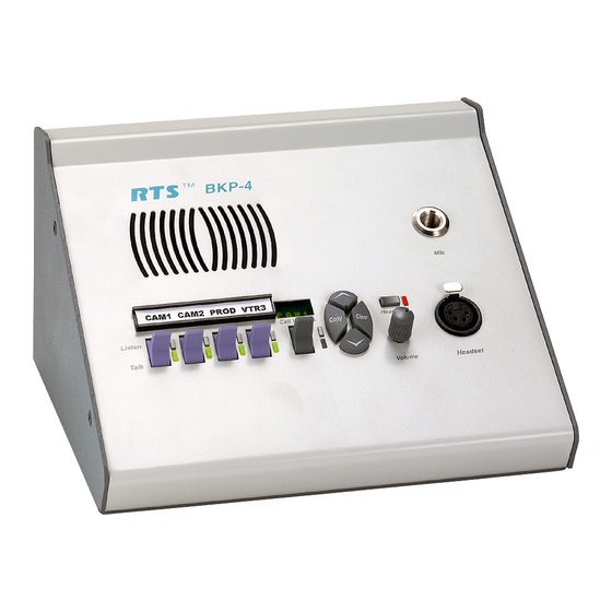
BKP-4 is suitable for desktop use and is powered from an ZEUSedit designation strip print feature. AC mains outlet. The TKP-4 is designed to fit in a Call Waiting Display (Optional on WKP-4) and Re- Tektronics equipment bay. The WKP-4 is designed for wall sponse Key: 4-character, alphanumeric display for mounting. -
Page 8: Back Panel / Circuit Board Switches And Connectors
BACK PANEL / CIRCUIT BOARD SWITCHES AND CONNECTORS 10) BKP-4: Universal Power Input: Accepts any mains voltage from 90-240 VAC, 47-63 Hz. TKP-4 and WKP-4: Terminals for DC power con- nection. 11) Intercom Frame Connectors. All units have both 90-240 VAC 9-pin female Dsub (DE9S) and RJ12 connectors. -
Page 9: Specifications
9" (229mm) wide x 2.8" (71mm) deep behind front panel. WKP-4 Mounting Box: See Figure 4. TKP-4: 5.2" (132mm) high x 8.38" (213mm) wide x 3.25" (83mm) deep behind front panel. BKP-4: 4.6" (117mm) high x 9" (229mm) wide x 7"... -
Page 10: Installation
If damage has occurred, immediately (within 24 Insert the TKP-4 into a Tektronics equipment bay so that hours of receipt of equipment) contact the carrier involved the spring clips are fully seated. -
Page 11: Address Switch
Use that Not used. Leave Open. number to set the keypanel Address switch. Note that address switch settings 0, and 9 through F are not used. User Instructions BKP-4, TKP-4, and WKP-4 Keypanels 11... -
Page 12: Connections
If you use either of these special configurations, make sure DIP switch 4 is set to the Close position (page 11). Figure 5. RJ12 Intercom cable wiring diagram For Headset connector specifications, see page 9. 12 User Instructions BKP-4, TKP-4, and WKP-4 Keypanels... -
Page 13: Power Connection
Check the intercom cable connections (in particular, the data connections). TKP-4 / WKP-4: Connect an optional AC adapter using the color-code information on the AC adapter and the ter- Several symptoms may occur if the keypanel address is in- minal pinout information in Figure 7. -
Page 14: Keypanel Setup
3) To select a particular scroll list, tap the Copy button. 2. Press up and release the call waiting key. This clears the call waiting display. (Dashes should display.) 14 User Instructions BKP-4, TKP-4, and WKP-4 Keypanels... -
Page 15: Printing Designation Strips
If the LED next to a key does not turn on when the key it activated, this means the key is not currently assigned. The electronic latching feature (DIP switch 5) must be enabled in order to use latching. See page details. User Instructions BKP-4, TKP-4, and WKP-4 Keypanels 15... -
Page 16: Intercom Key Operation For Different Types Of Key Assignments
The next caller's name Call key will then appear in the call waiting window, and you may press down on the call waiting key to talk back. 16 User Instructions BKP-4, TKP-4, and WKP-4 Keypanels... -
Page 17: Operation With The Tif-951 Telephone Interface
Press down and hold the call waiting key. Then tap an intercom key down or up to display the talk or listen assignment. You may press several keys in succession to check their assignments. Release the call waiting key when finished. User Instructions BKP-4, TKP-4, and WKP-4 Keypanels 17... -
Page 18: Table 1. Address Number Vs Intercom Port Numbers For 8-Port Audio I/O Cards (Adam And Adam Cs Intercom Systems)
719 727 735 743 751 759 767 775 783 791 799 608 616 624 632 640 648 656 664 672 680 688 696 704 712 720 728 736 744 752 760 768 776 784 792 800 18 User Instructions BKP-4, TKP-4, and WKP-4 Keypanels... -
Page 19: Table 2. Address Number Vs Intercom Port Numbers For 12-Port Audio I/O Cards (Adam Intercom Systems)
323 335 347 359 371 383 395 407 419 431 443 455 467 479 491 503 515 527 539 551 563 575 587 599 312 324 336 348 360 372 384 396 408 420 432 444 456 468 480 492 504 516 528 540 552 564 576 588 600 User Instructions BKP-4, TKP-4, and WKP-4 Keypanels 19...