Sign In
Upload
Manuals
Brands
RTS Manuals
Intercom System
Zeus
RTS Zeus Manuals
Manuals and User Guides for RTS Zeus. We have
11
RTS Zeus manuals available for free PDF download: User Manual, Operating Instructions Manual, User Instructions, Installation Instructions Manual, Specification Sheet
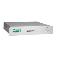
RTS Zeus User Manual (37 pages)
DSP Intercom Matrix
Brand:
RTS
| Category:
Intercom System
| Size: 0.7 MB
Table of Contents
Proprietary Notice
2
Customer Support
2
Return Shipping Instructions
2
Copyright Notice
2
Unpacking and Inspection
2
Warranty Information
2
Front View
3
Table of Contents
7
Read Me First
9
Introduction
9
Figure 1. Reference View for Zeus DSP Intercom Matrix
10
Zeus General Description
11
Table 1. the Types of Communication that Are Possible with Zeus
11
Specifications
12
Zeus
12
Zeusedit
12
Table 2. GPI Connector Pinout Specifications
12
Figure 2. Zeus and Accessory Dimensions
13
Figure 3. a Possible Intercom System Layout for the Sample Configuration File Named 1Studio.zus
14
About the Sample Configuration Files, 1Studio.zus and 2Studio.zus
15
Introduction
15
1Studio.zus Description
15
Table 3. a Printout of the Port Alpha List for the Sample Intercom Setup File 1Studio.zus
16
Table 4. a Printout of the IFB List for the Sample Intercom Setup File 1Studio.zus
17
Table 5. a Partial Printout of the IFB Configuration List for the Sample Intercom Setup File 1Studio.zus
18
Table 6. a Summary of the Toolbar Buttons that Are Used to Configure Resources
18
Figure 4. the Keypanel Setup Screen for the Director's Keypanel in the Example File 1Studio.zus
19
Figure 5. a Partial View of the Control Room DIM Table for the Example Intercom System 1Studio.zus
20
Figure 6. Accessing the Analog Input / Output Gain Adjustment
21
Figure 7. the Analog Input / Output Gain Adjustment Table
21
Figure 8. a Possible Intercom System Layout for the Sample Configuration File Named 2Studio.zus
23
Cables and Connectors
24
Introduction
24
Connectors
24
Types, Solder Vs Solderless
24
Pin Numbers
24
Cable Requirements
24
Figure 9. Connector Numbering
24
Figure 10. Cable Requirements
24
Cable Diagrams
25
Figure 11. Keypanel and TIF-951 Intercom Cable Wiring Diagram
25
Figure 12. a Cable to Connect a 4-Wire Intercom Station Other than a Keypanel
25
Figure 13. an Audio Output Cable from Zeus to an External Device
25
Figure 14. an Audio Input Cable to Connect an External Audio Source
25
Figure 15. Configuration Computer Cable
25
Figure 16. LCP-102 Interconnect Cable
25
Figure 17. UIO-256 Interconnect Cable
26
Figure 18. a Single-Channel "TW" Belt Pack Cable (for BP-318 Belt Pack)
26
Figure 19. a Power Distribution Cable for "TW" Belt Packs
26
Figure 20. an Audio Termination Plug for Use with the TW5W Splitter
26
Figure 21. a Cable to Connect a 4-Wire Channel from an SSA-324 to a Zeus Channel
26
Figure 22. 4020M Interconnect Cable
26
Installation Notes
27
General Installation Procedure
27
Unpacking the Equipment
27
Zeus Mounting Precautions
27
AC Power Connection
27
Computer Connection
27
Power-Up and Indications
28
Zeusedit Software Installation
28
Starting Zeusedit
28
Troubleshooting the Computer Connection
28
Keypanel Installation Notes
29
TIF-951 Telephone Interface Installation Notes
29
Single Audio Inputs
29
Table 7. ID DIP Switch Settings for the TIF-951
29
General Purpose Interface (GPI) Connector (J27)
30
7.13.1 General Description
30
7.13.2 Connections
30
7.13.3 Programming GPI Outputs
30
Figure 23. Typical GPI Input Connection
30
Figure 24. Typical GPI Output Connection
30
Figure 25. an Example of a Stacked Talk Key
31
Figure 26. Setting up a GPI Output to Activate Whenever Anyone Talks to a Particular Output Port
31
7.13.4 Programming GPI Inputs
32
UIO-256 Input/Output Frame
32
LCP-102 Level Control Panel
32
Using RTS TW Intercom Belt Packs with Zeus
32
Figure 27. Interfacing TW Belt Packs to Zeus
33
Advertisement
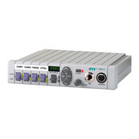
RTS Zeus User Manual (34 pages)
ZEUS KEYPANEL
Brand:
RTS
| Category:
Intercom System
| Size: 0.78 MB
Table of Contents
Proprietary Notice
2
Copyright Notice
2
Warranty Information
2
Customer Support
2
Return Shipping Instructions
3
Table of Contents
5
General Description
7
Features
7
Front Panel Description
8
Back Panel / Circuit Board Switches and Connectors
10
Specifications
12
Unpacking and Inspection
15
Wkp-4 Box Installation
16
Tkp-4 Box Installation
16
Configuration Switches
17
DIP Switches
17
DIP Switch 1
17
DIP Switch 2
17
DIP Switch 3
17
DIP Switch 4
17
DIP Switch 5
17
DIP Switch 6
18
DIP Switch 7
18
DIP Switch 8
18
Address Switch
18
Mounting the Mkp-4
21
Connections
22
MIC Connector
22
Headset Connector
22
Connection to Intercom System
22
BKP-4 Connection
23
TKP-4 / WKP-4 Connection
24
Power Connection
24
Startup and Operational Check
25
Assigning Intercom Keys
27
Clearing Key Assignments
28
Changing Setup Pages
28
Headset Button Operation
31
DIP Switch 4 in Open Position (Default)
31
DIP Switch 4 in Closed Position
31
Volume Adjustment
31
Intercom Key Operation
32
Momentary Vs. Latching Operation
32
Intercom Key Operation for Different Types of Key Assignments
32
Intercom Key Indications
32
Talk Indicator
32
Listen Indicator
33
Call Waiting Operation for Incoming Calls
33
Operation with the Tif-951 & Tif-2000 Telephone Interface
33
Displaying Key Assignments
34
Displaying the Port Number
34
Sidetone Adjustment
34
RTS Zeus Installation Instructions Manual (22 pages)
ADAM, ADAM CS, AND ZEUS INTERCOM SYSTEMS
Brand:
RTS
| Category:
Intercom System
| Size: 0.19 MB
Table of Contents
Installation Instructions
1
Proprietary Notice
2
Customer Support
2
Copyright Notice
2
Return Shipping Instructions
2
Unpacking and Inspection
2
Warranty Information
2
Table of Contents
5
Introduction
7
New Features for Version 8.2
7
Figure 1. KP98-7 Reference View
7
Installation
8
General
8
Figure 2. EKP98-0 Reference View
8
Figure 3. LCP-100A Reference View
8
Unpacking and Inspection
9
Checking the Factory Jumper and Level Settings
9
Dip Switch Settings
9
Talk Key Row Selection
9
Expansion Panel In-Use Indication for IFB and ISO
9
LCP Selection
9
Logical Keypanel Address Selection
9
Table 1. DIP Switch Summary
9
Baud Rate
10
Mounting the Keypanel and Accessories
10
Standard Connections
10
Gooseneck Microphone
10
Front Panel Headset
10
Connection to Intercom Matrix
10
Optional Connections
11
EKP98-0 and LCP-100A
11
Figure 4. 9-Pin Intercom Cable Wiring Diagram
11
Figure 5. RJ-11 Intercom Cable Wiring Diagram
11
Table 2. 9-Pin FRAME Connector Pin-Out
11
Table 3. RJ-11 FRAME Connector Pin-Out
11
Figure 6. Typical Interconnections between the KP98-7, EKP98-0, and LCP-100A
12
Figure 7. Terminal Block Wiring Diagram for KP-96-RC Option
12
Rear Panel Headset Connection
13
Terminal Block Connections
13
EXT MIC in Connector
13
EXT LINE in Connector
13
MIC PRE out Connector
13
Table 4. EXT MIC in Connector Pin-Out
13
Table 5. EXT LINE in Connector Pin-Out
13
Table 6. Rear Panel Headset Connector Pin-Out
13
Table 7. MIC PRE out Connector Pin-Out
13
Power-Up and Operational Check
14
Keypanel Programming
14
Electrical Adjustments
14
Internal Jumpers
14
J201 (External Input Muting)
14
J202 (Speaker/Hdst Mute)
14
Figure 8. Locations of Internal Jumpers and Trimmers
15
J203 (Sidetone Muting)
16
J401 (Output Enable)
16
J402 (Balance Test)
16
J403 (Preamp Out)
16
J404-J406 (Panel MIC Selection)
16
Audio Level Adjustments
16
General
16
Microphone Preamplifier
16
Speaker/Headset Amplifier Adjustments
18
Table 8. Correspondence between Address Numbers and Intercom Port Numbers for ADAM Intercom Systems
20
Advertisement
RTS Zeus Installation Instructions Manual (22 pages)
ADAM, ADAM CS, AND ZEUS INTERCOM SYSTEMS
Brand:
RTS
| Category:
Intercom System
| Size: 0.87 MB
Table of Contents
Installation Instructions
1
Proprietary Notice
2
Customer Support
2
Copyright Notice
2
Return Shipping Instructions
2
Warranty Information
2
Table of Contents
5
Introduction
7
New Features for Version 8.3G
7
Figure 1. KP96 / KP97 Reference View
7
Installation
8
General
8
Figure 2. EKP96 / EKP97 Expansion Panel Reference View
8
Figure 3. LCP-100A Level Control Panel Reference View
8
Unpacking and Inspection
9
Checking the Factory Jumper and Level Settings
9
Dip Switch Settings
9
Combinations of Expansion and Level Control Panels
9
Winking on / off
9
Logical Keypanel Address Selection
9
Table 1. DIP Switch Summary
9
Baud Rate
10
Mounting the Keypanel and Accessories
10
Standard Connections
10
Gooseneck Microphone
10
Front Panel Headset
10
Connection to Intercom Matrix
10
Optional Connections
11
Expansion Panels and LCP-100A
11
Figure 4. 9-Pin Intercom Cable Wiring Diagram
11
Figure 5. RJ-11 Intercom Cable Wiring Diagram
11
Table 2. 9-Pin FRAME Connector Pin-Out
11
Table 3. RJ-11 FRAME Connector Pin-Out
11
Figure 6. Typical Interconnections
12
Figure 7. Terminal Block Wiring Diagram for KP-96-RC Option
12
Rear Panel Headset Connection
13
Terminal Block Connections
13
EXT MIC in Connector
13
EXT LINE in Connector
13
MIC PRE out Connector
13
Table 4. EXT MIC in Connector Pin-Out
13
Table 5. EXT LINE in Connector Pin-Out
13
Table 6. MIC PRE out Connector Pin-Out
13
Table 7. Rear Panel Headset Connector Pin-Out
13
Power-Up and Operational Check
14
Keypanel Programming
14
Electrical Adjustments
14
Internal Jumpers
14
J201 (External Input Muting)
14
J202 (Speaker/Hdst Mute)
14
Figure 8. Locations of Internal Jumpers and Trimmers
15
J203 (Sidetone Muting)
16
J401 (Output Enable)
16
J402 (Balance Test)
16
J403 (Preamp Out)
16
J404-J406 (Panel MIC Selection)
16
Audio Level Adjustments
16
General
16
Microphone Preamplifier
16
Speaker/Headset Amplifier Adjustments
18
Table 8. Correspondence between Address Numbers and Intercom Port Numbers for ADAM Intercom Systems
20
RTS Zeus User Instructions (27 pages)
ADAM, ADAM CS, AND ZEUS INTERCOM SYSTEMS
Brand:
RTS
| Category:
Intercom System
| Size: 2.43 MB
Table of Contents
Proprietary Notice
2
Customer Support
2
Copyright Notice
2
Return Shipping Instructions
2
Unpacking and Inspection
2
Warranty Information
2
Table of Contents
5
Description and Specifications
7
General Description
7
Features
7
Front Panel Description
7
Figure 1. Front Panel View
7
Back Panel / Circuit Board Switches and Connectors
8
Figure 2. BKP-4 Back Panel View
8
Figure 3. WKP-4/TKP-4 Configuration Switches and Connectors on Circuit Board (WKP-4 Shown)
8
Specifications
9
Figure 4. WKP-4 Mounting Box Dimensions
9
Installation
10
Unpacking and Inspection
10
Wkp-4 Box Installation
10
Tkp-4 Box Installation
10
Configuration Switches
10
DIP Switches
10
Address Switch
11
Connections
12
MIC Connector
12
Headset Connector
12
Connection to Intercom System
12
Figure 5. RJ12 Intercom Cable Wiring Diagram
12
Power Connection
13
Startup and Operational Check
13
Figure 6. 9-Pin Intercom Cable Wiring Diagram
13
Figure 7. Intercom and Power Terminal Block Pinouts for the TKP-4 / WKP-4
13
Figure 8. Use Tie Wraps to Secure the Cables (WKP-4 Installation)
13
Figure 9. Call Waiting Window and Key
13
Keypanel Setup
14
Assigning Intercom Keys
14
Clearing Key Assignments
14
Figure 10. Scroll, Copy and Clear Buttons
14
Printing Designation Strips
15
Changing Setup
15
Operation
15
Headset Button Operation
15
DIP Switch 4 in Open Position (Default)
15
DIP Switch 4 in Closed Position
15
Intercom Key Operation
15
Momentary Vs Latching Operation
15
Intercom Key Operation for Different Types of Key Assignments
16
Intercom Key Indications
16
Call Waiting Operation for Incoming Calls
16
Operation with the Tif-951 Telephone Interface
17
Displaying Key Assignments
17
Displaying the Port Number
17
Table 1. Address Number Vs Intercom Port Numbers for 8-Port Audio I/O Cards (ADAM and ADAM CS Intercom Systems)
18
Table 2. Address Number Vs Intercom Port Numbers for 12-Port Audio I/O Cards (ADAM Intercom Systems)
19
RTS Zeus Installation Instructions Manual (20 pages)
ADAM, ADAM CS, AND ZEUS INTERCOM SYSTEMS
Brand:
RTS
| Category:
Intercom System
| Size: 0.19 MB
Table of Contents
Installation Instructions
1
Proprietary Notice
2
Customer Support
2
Copyright Notice
2
Return Shipping Instructions
2
Warranty Information
2
Table of Contents
5
Introduction
7
Figure 1. KP95-0 Keypanel Reference View
7
Figure 2. EKPD-95 Expansion Panel Reference View
7
Installation
8
General
8
Unpacking and Inspection
8
Checking the Factory Jumper and Level Settings
8
Dip Switch Settings
8
Logical Keypanel ID Selection
8
Table 1. DIP Switch Summary
8
Baud Rate
9
Mounting the Keypanel and Accessories
9
Standard Connections
9
Gooseneck Microphone
9
Connection to Intercom Matrix
9
Keypanel Programming
9
Printing Designation Strips
10
Optional Connections
10
Expansion Panels
10
Rear Panel Headset Connection
10
Figure 3. 9-Pin Intercom Cable Wiring Diagram
10
Figure 4. RJ-11 Intercom Cable Wiring Diagram
10
Table 2. 9-Pin FRAME Connector Pin-Out
10
Table 3. RJ-11 FRAME Connector Pin-Out
10
Terminal Block Connections
11
EXT MIC in Connector
11
Figure 5. Optional Interconnections
11
Figure 6. Terminal Block Wiring Diagram
11
Table 4. Rear Panel Headset Connector Pin-Out
11
EXT LINE in Connector
12
MIC PRE out Connector
12
Power-Up and Operational Check
12
Electrical Adjustments
12
Internal Jumpers
12
Table 5. EXT LINE in Connector Pin-Out
12
Table 6. MIC PRE out Connector Pin-Out
12
Table 7. EXT MIC in Connector Pin-Out
12
J201 (External Input Muting)
13
J202 (Speaker/Hdst Mute)
13
J203 (Sidetone Muting)
13
J401 (Output Enable)
13
J402 (Balance Test)
13
J403 (Preamp Out)
13
J404-J406 (Panel MIC Selection)
13
Audio Level Adjustments
13
General
13
Microphone Preamplifier
13
Figure 7. Locations of Internal Jumpers and Trimmers
14
Table 8. Correspondence between Address Numbers and Intercom Port Numbers for ADAM Intercom Systems
18
RTS Zeus Operating Instructions Manual (31 pages)
KEYPANELS VERSION 8.3G
Brand:
RTS
| Category:
Intercom System
| Size: 0.38 MB
Table of Contents
Operating Instructions
1
Table of Contents
3
List of Figures
4
List of Tables
4
Introduction
5
Description of User Controls and Features
6
Basic Keypanel Operation
7
Power Switch
7
Power-Up Indications
7
Using a Headset with the Keypanel
7
Volume Adjustment
7
Placing a Call
7
Receiving Calls from Other Keypanels
8
Advanced Operations
9
General
9
Keypad Key Labeling
9
Display Requests
9
Display Requests Using Keypad Sequences
9
Display Requests Using Scrolling
11
Assigning Setup
12
Programming Talk and Listen Keys
14
General
14
Programming Key Assignments Using Keypad Numeric Entry
14
Programming Key Assignments Using Copy
25
Programming Key Assignments Using Alpha Scrolling
27
Clearing or Canceling a Key Assignment
29
Activating the Tone Generator
31
CALLING a DESTINATION that DOES NOT HAVE a Talk KEY ASSIGNED
31
RTS Zeus User Instructions (18 pages)
Dual Digital Hybrid ADAM, ADAM CS, Zeus Intercom Systems
Brand:
RTS
| Category:
Intercom System
| Size: 0.77 MB
Table of Contents
Table of Contents
3
1 Description and Specifications
5
General Description
5
General Features
5
Front and Back Panel Descriptions
6
Front Panel
6
Back Panel
6
Specifications
6
2 Installation
7
Unpacking and Inspecting
7
Mounting
7
4-Wire Audio Connections
7
Adam, Adam Cs, or Zeus Audio Connection
7
Audio Connections for Other 4- Wire Communications Systems
7
2- Wire Audio Connections
9
Rts Tw Audio Connections
9
Audiocom Audio Connection
9
Clear -Com Audio Connection
10
Ther Wire Udio Onnection
10
4- Wire Call Signal Connections
11
Call Signal Connections for Adam, Adam Cs, and Zeus
11
Call Signal Connections for Other 4-Wire Communicaton Systems
13
4-Wire Call Send and Call Enable /Inhibit
13
4-Wire Call Receive
13
2-Wire Call Signal
14
Call Signal Connections for Audiocom , Rts Tw and Clear -Com
14
Call Signal Connections for Other 2-Wire Communication System
14
R Eceive
14
3 Operation
15
General Instructions
15
Operating Notes for Adam, Adam Cs, and Zeus Intercom Systems
15
4 Appendix
16
Internal Access
16
Mode Dip Switch Settings
16
Evel Isplay Alibration
16
All Ignal Ption Ard Nstallation
17
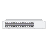
RTS Zeus User Manual (10 pages)
Level Control Panel ADAM, ADAM CS, and ZEUS Intercom Systems
Brand:
RTS
| Category:
Control Panel
| Size: 0.24 MB
Table of Contents
Table of Contents
3
Introduction
4
Lcp-102 Description
4
Figure 1. LCP-102 Reference View
4
Package Contents
5
Installation
5
Location and Mounting
5
Connections
5
Power-Up and Initial Settings
5
Applying Power
5
Programming Menus
5
Setting the Panel Address
5
Table 1. the LCP-102 Programming Menus
5
Adjusting the Dimmer
6
Operation
6
Panel Mode Selection
6
Page Select
6
TRIMS Mode Assignments and Operation
6
PAP Mode Asignments and Operation
6
CDP Mode Assignments and Operation
7
Saving Configuration Changes
8
Figure 2. Typical Connection Methods for the LCP-102
9
Figure 3. Interconnect Cable from a Zeus or ADAM Intercom System to the LCP-102
10
RTS Zeus Operating Instructions Manual (8 pages)
ADAM, ADAM CS, AND ZEUS INTERCOM SYSTEMS
Brand:
RTS
| Category:
Intercom System
| Size: 0.1 MB
Table of Contents
Operating Instructions
1
Table of Contents
3
Description of User Controls and Features
4
Introduction
4
Receiving Calls from Other Keypanels
5
Keypanel Operation
5
Power Switch
5
Volume Adjustment
5
Placing a Call
5
KP95-0 Keypanel
5
RTS Zeus Specification Sheet (2 pages)
RTS Digital Matrix Intercom System Specification Sheet
Brand:
RTS
| Category:
Intercom System
| Size: 0.51 MB
Advertisement
Related Products
RTS Zeus III
RTS Zeus II
RTS 4001
RTS 4001M
RTS 4002
RTS 4002M
RTS 4003
RTS 4003M
RTS 4020
RTS 802
RTS Categories
Intercom System
Toy
Recording Equipment
Power Supply
Control Panel
More RTS Manuals
Login
Sign In
OR
Sign in with Facebook
Sign in with Google
Upload manual
Upload from disk
Upload from URL