Ferris IS2000Z Series Operator's Manual
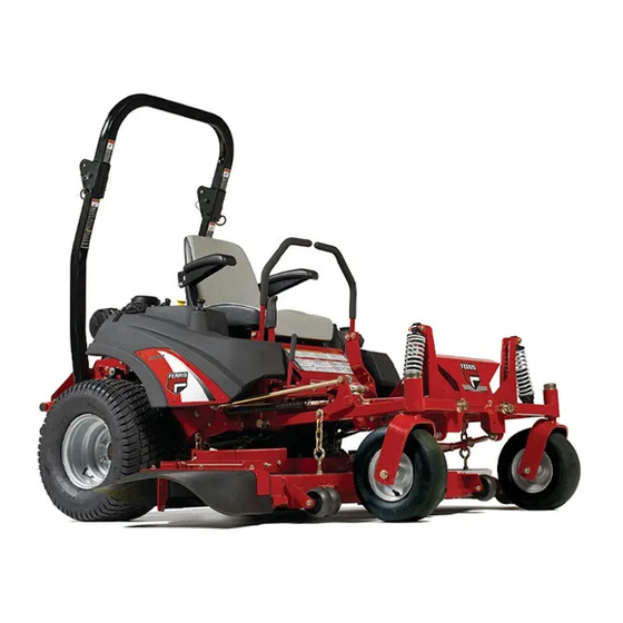
Is2000z series zero-turn riding mower
Hide thumbs
Also See for IS2000Z Series:
- Operator's manual with setup instructions (44 pages) ,
- Operator's manual (56 pages) ,
- Operator's manual (44 pages)
Table of Contents
Advertisement
Briggs & Stratton Power Products Group, LLC.
5375 North Main Street
Munnsville, NY 13409
800-933-6175
OPERATOR'S
MANUAL
IS2000Z Series
Zero-Turn Riding Mower
Model No.:
Description:
5900807
IS2000ZKAV3461SS
5900808
IS2000ZKAV2761
5900811
IS2000ZB3061SS
5900814
IS2000ZBV3061SS AUS/NZ
5900816
IS2000ZB3061SS CAL
5900840
IS2000ZKAV2552
5900879
IS2000ZKAV2661
5900945
IS2000ZKAV2652
5900939
IS2000ZKAV2652HT
5900968
IS2000ZB3061
5901025
IS2000ZKAV2661
5900587
IS2000ZB2852
5900536
IS2000ZB3061
5900586
IS2000ZB3261
5900563
IS2000ZKAV2652
5101940
Rev H
Advertisement
Table of Contents
Troubleshooting

Related Manuals for Ferris IS2000Z Series


Summary of Contents for Ferris IS2000Z Series
- Page 1 OPERATOR’S MANUAL IS2000Z Series Zero-Turn Riding Mower Model No.: Description: 5900807 IS2000ZKAV3461SS 5900808 IS2000ZKAV2761 5900811 IS2000ZB3061SS 5900814 IS2000ZBV3061SS AUS/NZ 5900816 IS2000ZB3061SS CAL 5900840 IS2000ZKAV2552 5900879 IS2000ZKAV2661 5900945 IS2000ZKAV2652 5900939 IS2000ZKAV2652HT 5900968 IS2000ZB3061 5901025 IS2000ZKAV2661 5900587 IS2000ZB2852 5900536 IS2000ZB3061 5900586 IS2000ZB3261...
- Page 2 Thank you for purchasing this quality-built FERRIS product. We’re pleased that you’ve placed your confidence in the FERRIS brand. When operated and maintained according to the instructions in this manual, your FERRIS product will provide many years of dependable service.
-
Page 3: Table Of Contents
Table of Contents Troubleshooting, Adjustments & Service ..27 Operator Safety ..........2 Troubleshooting the Tractor ........27 Safety Decal Locations .........11 Troubleshooting the Mower ........28 Safety Interlock System ........12 Troubleshooting Common Cutting Problems ..29 Features & Controls ......... 13 Seat Adjustment ............30 Identification Numbers ..........13 Ground Speed Control Lever Adjustment .....30 Control Functions ..........13... -
Page 4: Operator Safety
Operator Safety Operating Safety Congratulations on purchasing a superior-quality piece of lawn and garden equipment. Our products are designed and manufactured to meet or exceed all industry standards for safety. Do not operate this machine unless you have been trained. Reading and understanding this operator’s manual is a way to train yourself. -
Page 5: Slope Operation
Operator Safety Slope Operation Operation on slopes can be dangerous. Using the unit on a slope that is too steep where you do not have adequate wheel traction (and control) can cause sliding, loss of steering, control, and possible rollover. You should not operate on a slope greater than a 5.4 foot rise over a 20 foot length (15 degrees). - Page 6 Operator Safety Roll Bar Use Keep the roll bar in the raised position and fasten the seat belt. There is no roll over protection when the roll bar is down! Do not jump off if the mower tips (it is safer to be secured by the seat belt with the roll bar raised.) Lower the roll bar only when necessary (such as to temporarily clear a low overhanging obstacle) and...
- Page 7 Operator Safety Fuel and Maintenance Always disengage all drives, shutoff the engine, and remove the key before doing any cleaning, refueling, or servicing. Gasoline and its vapors are extremely flammable. Do not smoke while operating or refueling. Do not add fuel while engine is hot or running.
- Page 8 Operator Safety Read these safety rules and follow them closely. Failure to obey these rules could result in loss of control of unit, severe personal injury or death to you, or bystanders, or damage to property or equipment. This mowing deck is capable of amputating hands and feet and throwing objects. The triangle in text signifies important cautions or warnings which must be followed.
- Page 9 Operator Safety 23. Use care when approaching blind corners, shrubs, 5. Use extra care with grass catchers or other trees or other objects that may obscure vision. attachments. These can change the stability of 24. To reduce fire hazard, keep unit free of grass, the unit.
- Page 10 Operator Safety EMISSIONS where there is an open flame, such as in a water heater. Allow unit to cool before storing. 1. Engine exhaust from this product contains 5. Shut off fuel while storing or transporting. Do not chemicals known, in certain quantities, to cause store fuel near flames or drain indoors.
- Page 11 Operator Safety leaks. Make sure all hydraulic fluid connections To maintain operator roll over protection and roll bar are tight and all hydraulic hoses and lines are in effectiveness: good condition before applying pressure to the • If a ROLL BAR becomes damaged for any reason, system.
- Page 12 Operator Safety WARNING INSPECT BUCKLE & LATCH Failure to properly inspect and maintain the seat belt can cause serious injury or death. INSPECTION AND MAINTENANCE OF THE ROLL BAR SEAT BELT • The seat belt like the ROLL BAR, needs to be periodically inspected to verify that the integrity has not been compromised through normal machine use, misuse, age degradation,...
-
Page 13: Safety Decal Locations
Operator Safety Safety Decal Locations Before operating your unit, read the safety decals. The cautions and warnings are for your safety. To avoid a personal injury or damage to the unit, understand and follow all the safety decals. WARNING If any safety decals become worn or damaged, and cannot be read, order replacement decals from your dealer. -
Page 14: Safety Interlock System
Operator Safety Safety Icons The alert symbol is used to identity safety Safety Interlock System information about hazards that can result in personal injury. A signal word (DANGER, WARNING, or CAUTION) is used with the alert symbol to indicate the likelihood and the potential severity of the injury. This unit is equipped with safety interlock switches. -
Page 15: Features & Controls
Features & Controls Features & Controls Deck Lift Pedal, Cutting Height Adjustment Pin & Deck Lift Lock Identification Number Location Lever: These control the cutting height of the mower deck. Depress the pedal until it locks into the 5” (12,7 cm) position. Place the adjustment pin in the desired cutting height and release the lift lock lever. -
Page 16: Operation
Features & Controls Ground Speed Control Levers: These WARNING levers control the ground speed of the Never allow passengers to ride on the unit. rider. The left lever controls the left rear Before leaving the operator’s position for any drive wheel and the right lever controls reason, engage the parking brake, disengage the right rear drive wheel. -
Page 17: Starting The Engine
Operation 3. Engage the parking brake by pulling the handle up until it locks into position. 4. Move the throttle control to mid-throttle position and turn the ignition key to OFF. Remove the key. Pushing the Rider by Hand DO NOT TOW RIDER Towing the unit will cause hydraulic pump and wheel motor damage. -
Page 18: Zero Turn Driving Practice
Operation Zero-Turn Driving Practice Smooth Travel The lever controls of The lever controls of the Zero Turn rider are the Zero Turn rider are responsive, and learning to gain a smooth and responsive. efficient control of the rider’s forward, reverse, and turning movements will take some practice. - Page 19 Operation Practice Turning Around a Corner Practice Turning In Place While traveling forward allow one handle to gradually To turn in place, “Zero Turn,” gradually move one return back toward neutral. Repeat several times. ground speed control lever forward from neutral and one lever back from neutral simultaneously.
-
Page 20: Mowing
Operation The amount of grass you are able to cut in one pass Mowing is also effected by the type of mowing system you are 1. Engage the parking brake. Make sure the PTO using (for example, broadcasting with side discharge switch is disengaged, the motion control levers decks can process a much larger volume of grass are locked in the NEUTRAL position and the... -
Page 21: Mowing Methods
Operation 3. For a truly professional cut, mow across the lawn gear or slower for manual gear models). If you hear in one direction, then recut the lawn by mowing the engine slowing down you are mowing too fast, use a slower ground speed. -
Page 22: Attaching A Trailer
Operation and quality of your lawn. We recommend that you To raise the roll bar: experiment with both the cutting height and ground 1. Pull the hair pin clips (A) out of the retainer pins speed until you achieve the best cut. Start with a high (B) and remove the retainer pins. -
Page 23: Storage
Operation Storage WARNING Temporary Storage (30 Days Or Less) Never store the unit, with gasoline in engine or fuel tank, in a heated shelter or in enclosed, Remember, the fuel tank will still contain some poorly ventilated enclosures. Gasoline fumes gasoline, so never store the unit indoors or in any may reach an open flame, spark or pilot light other area where fuel vapor could travel to any... -
Page 24: Regular Maintenance
Regular Maintenance Check Tire Pressures Maintenance Tire pressure should be checked periodically, and Maintenance Schedule maintained at the levels shown in the chart. Note that these pressures may differ slightly from the “Max The following schedule should be followed for normal Inflation”... -
Page 25: Oil & Filter Change
Reinstall the oil drain hose into the will drain the oil reservoir. Have a suitable container cable clamp to retain the hose during normal ready to catch any spilled oil. Ferris recommends this operation. be a dealer-only service item. -
Page 26: Battery Maintenance
Regular Maintenance Battery Maintenance Not all greases are compatible. Red Grease (p/n 5022285) is recommended, automotive-type high- NOTE: This unit is equipped with a maintenance-free temperature, lithium grease may be used when this is BCIU1 battery. not available. WARNING Oil: Be careful when handling the battery. -
Page 27: Servicing The Mower Blades
Regular Maintenance Lubricating the Front Casters C.) Mower blade is bent or broken. 3. If the cutting edges are not sharp or have nicks, NOTE: Casters should be lubricated annually. sharpen the blades. See SHARPENING THE 1. Remove the 1/4-28 bolt (A, Figure 20) screw into MOWER BLADES. - Page 28 Troubleshooting, Adjustment & Service Sharpening the Mower Blades CAUTION Avoid injury. Mower blades are sharp. • Always wear gloves when handling mower blades or working near blades. • Always wear safety eye protection when grinding 1. Sharpen the mower blade with a grinder, hand file, or electric blade sharpening.
-
Page 29: Troubleshooting, Adjustments & Service
Troubleshooting, Adjustment & Service Troubleshooting WARNING While normal care and regular maintenance will To avoid serious injury, perform maintenance extend the life of your equipment, prolonged or on the tractor or mower only when the engine constant use may eventually require that service be is stopped and the parking brake engaged. -
Page 30: Troubleshooting The Mower
Troubleshooting, Adjustment & Service Rider Troubleshooting Continued. PROBLEM CAUSE REMEDY Hydraulic release valve(s) in Turn valve(s) clockwise to close. “open” position. Engine runs but rider will not Belt is broken. See Drive Belt Replacement drive. Drive belt slips. See problem and cause below. Brake is not fully engaged. -
Page 31: Troubleshooting Common Cutting Problems
Troubleshooting, Adjustment & Service Troubleshooting Common Cutting Problems PROBLEM CAUSE REMEDY Streaking Sharpen your blades. Blades are not sharp Replace your blades. Blades are worn down too far. Always mow at FULL throttle. Engine speed is too slow. Slow down. Ground speed is too fast. -
Page 32: Seat Adjustment
Troubleshooting, Adjustment & Service Seat Adjustment Seat Adjustment See Figure 27. The seat can be adjusted forward Lever and back. Move the lever towards the left, position the seat as desired, and release the lever to lock the seat into position. Seat Adjustment (Suspension Seat) See Figure 28. -
Page 33: Speed Balancing Adjustment
Troubleshooting, Adjustment & Service Speed Balancing Adjustment If the rider veers to the right or left when the ground speed control levers are in the maximum forward position, the top speed of each of these levers can be balanced by turning the adjustment bolt(s) (A, Figure 30). -
Page 34: Return To Neutral Adjustment
Figure 33. Parking Brake Adjustment A. Brake Spring Do not adjust the spring to be shorter than B. Adjustment Nut 1-15/16” (4,9 cm) when compressed. This may damage the brake mechanism. If this does not correct the braking problem, see your Ferris dealer. www.ferrisindustries.com... -
Page 35: Rear Suspension Adjustment
Troubleshooting, Adjustment & Service Suspension Adjustment To adjust the upper mounting position: 1. Park machine on a flat, level surface. Disengage The shock assembly can be adjusted to vary the the PTO, stop the engine and engage the parking amount of pre-load applied to the springs. This allows brake. -
Page 36: Mowing Height Adjustment
Troubleshooting, Adjustment & Service Mowing Height Adjustment The cutting height adjustment pin (A, Figure 35) controls the mower cutting height. The cutting height is adjustable between 1-3/4” (4,4 cm) and 5” (12,7 cm) in 1/4” (0,64 cm) increments. 1. Depress the deck lift foot pedal (B) until it locks into the 5”... -
Page 37: Deck Lift Rod Timing Adjustment
Troubleshooting, Adjustment & Service Deck Lift Rod Timing Adjustment Inner Rod 1. Park machine on a flat, level surface. Disengage the PTO, stop the engine and engage the parking brake. Rear tires must be inflated to 15 psi (1,03 bar); front tires to 25 psi (1,72 bar). 2. -
Page 38: Deck Leveling Adjustment
Troubleshooting, Adjustment & Service Deck Leveling Adjustment NOTE: Before adjusting the deck level, the deck lift rod timing must be checked and/or adjusted. 1. Park machine on a flat, level surface. Disengage the PTO, stop the engine and engage the parking brake. -
Page 39: Hydraulic Pump Drive Belt Replacement
Troubleshooting, Adjustment & Service Deck Lift Spring The deck lift springs (A, Figure 43) are factory set to provide optimal lifting performance. Although it is fastened with a multi-position anchor, this is NOT AN ADJUSTMENT POINT. DO NOT attempt to adjust the spring length or lifting performance will be compromised. -
Page 40: Mower Belt Replacement
Troubleshooting, Adjustment & Service Mower Belt Replacement 52” Deck To avoid damaging belts, DO NOT PRY BELTS OVER PULLEYS. 1. Park the tractor on a smooth, level surface such as a concrete floor. Disengage the PTO, engage the parking brake, turn off the engine, and remove the ignition key. - Page 41 Troubleshooting, Adjustment & Service 52” Deck 61” Deck Figure 46. Mower PTO Belt Routing A. Spindle Pulley B. PTO Drive Belt C. Spring-loaded Idler Pulley D. Stationary Idler Pulley Check the Mower Belt Idler Spring Tensioner Spring Length 1. Park the machine on a smooth level surface such as a concrete floor.
-
Page 42: Battery Service
Troubleshooting, Adjustment & Service Battery Service battery is fully charged when the cells are gassing freely at low charging rate and less than 0.003 change in specific gravity occurs over a three hour WARNING period. Keep open flames and sparks away from the Jump Starting With Auxiliary (Booster) Battery battery;... - Page 43 Troubleshooting, Adjustment & Service THIS HOOK-UP FOR NEGATIVE GROUND VEHICLES Starter Starter Switch Switch Jumper Cable Starting Discharged Vehicle Vehicle Battery Battery Jumper Cable To Ground Engine Block MAKE CERTAIN VEHICLES DO NOT TOUCH Figure 48. Jump Starting WARNING WARNING Any procedure other than the preceding could For your personal safety, use extreme care result in:...
-
Page 44: Specifications
Specifications Displacement 49.43 Cu. in (810 cc) Specifications Electrical System 12 volt, 16 amp. Alternator; Battery: 340 cca NOTE: Specifications are correct at time of printing Oil Capacity 2.1 US qt. (2.0 L) w/ filter and are subject to change without notice. 30 Gross HP* Briggs &... - Page 45 Specifications †Power Ratings: All power levels are stated gross horsepower per SAE J2723 as rated by Kawasaki and tested per the SAE J1995 test standard. The gross power curves and more information can be viewed at www.kawasaki-criticalpower.com. *Power Ratings: The gross power rating for individual gas engine models is labeled in accordance with SAE (Society of Automotive Engineers) code J1940 (Small Engine Power &...
-
Page 46: Slope Identification Guide
www.ferrisindustries.com... - Page 47 Ferris dealer during the warranty period. Ferris’ obligation under this limited warranty is, at Ferris’ option, to repair or replace any part or parts of the mower, which, in the judgment of Ferris, are found to be defective and covered by this limited warranty.
- Page 48 OPERATOR’S MANUAL IS2000Z Series Zero-Turn Riding Mower Briggs & Stratton Power Products Group, LLC. 5375 North Main Street Munnsville, NY 13409 800-933-6175 www.ferrisindustries.com...