Extron electronics MLC 226 IP Series Setup Manual
Mlc 226 ip series medialink controller setup guide
Hide thumbs
Also See for MLC 226 IP Series:
- Specifications (5 pages) ,
- Setup manual (25 pages) ,
- Installation manual (164 pages)
Advertisement
Quick Links
Download this manual
See also:
Setup Manual
MLC 226 IP Series • Setup Guide
The Extron MLC 226 IP Series MediaLink
AV systems to allow users to remotely control, monitor, and troubleshoot AV equipment, including display devices and
switchers. It includes an embedded web server, multiple serial ports, relays, and configurable digital I/O ports for use in
applications that require control and monitoring of multiple devices within an AV system.
The MLC 226 IP series of controllers are configured using the free Extron Global Configurator (GC) software. The MLCs
integrate seamlessly with Extron GlobalViewer
resource management software for remote control applications. Global Configurator and other useful software applications
are available at www.extron.com.
A checklist of basic setup steps is provided at the end of this guide. For additional information see the help files and the
MLC 226 IP Series User Guide, available at www.extron.com.
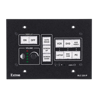
Panels and Features
Function or
Display On and
Off Buttons
Buttons
DISPLAY
ON
OFF
VOLUME
Front Panel
Volume Knob
and LEDs
Cabling and Features
Attach cables using the following wiring diagrams as a guide. Full details are available in the MLC 226 IP Series User Guide.
CAUTION:
Installation and service must be performed by authorized personnel only.
Control — Projector or Display
Projector
Ground (
or Display
IR Port
IR transmit (Tx)
Projector or
Display
RS-232 Port
Ground (
)
Ground (
Receive (Rx)
Receive (Rx)
Transmit (Tx)
Transmit (Tx)
Bidirectional
®
Controller integrates Ethernet connection into
Enterprise (GVE) software and the free GlobalViewer web-based AV
®
Room
Input Selection
Control
Buttons
AUTO
IMAGE
AUX
VCR
DVD
VIDEO
SCREEN
2
3
1
UP
4
5
6
DOC
LAPTOP
PC
CAM
SCREEN
DOWN
IR
CONFIG
MLC 226 IP
IR Control
IR Learning
Config (RS-232
Receiver
Receiver
host control) Port
)
Digital input
Ground ( )
or
or
)
Power sense
Ground ( )
+12VDC
PROJECTOR
A B C
CM/ IR
RS-232/IR
Bottom
Panel
Rear Panel
Reset Button
and LED
(on side)
IP Intercom
Ports
Projector
Control
Control
Module/IR/
Port
SCP Ports
PROJECTOR
A B C D E
CM/ IR SCP
RS-232/IR
Bottom Panel
{
On, high: >2.8 VDC
Digital Input
Off, low: <2.0 VDC
Tip (+12 V)
Ring
(signal)
Sleeve ( )
3.5 mm Stereo Plug
Projector RS-232 / IR / Digital Input Port(s)
Select RS-232 protocol via
Infrared:
software or SIS command.
• TTL level (0 to 5 V)
Signals are bidirectional, ±5 V.
• Up to 1 MHz
RS-232 default protocol:
Digital input:
• 9600 baud
• 8 data bits • 1 stop bit
• High: >2.8 VDC
• no parity
• no flow control
• Low: <2.0 VDC
HOST
CONTROL
1=DIGITAL I/O
2=Tx 3=Rx 5=GND
38400, N, 8, 1
PRESS TAB WITH
TWEEKER TO REMOVE
IR/Serial
MLS
Power
Relay
Output
Switcher
Input
Ports
Ports
Port
(12 VDC)
1 2
3 4
5 6
S
S
S
A B
A
B
C
A
B
C
MLS PWR
IR/SERIAL OUT
RELAYS
RS-232 12V
NORMALLY OPEN
Extron
Power Sensor
(60-271-01)
NOTE: Each projector or display may
require different wiring. See the
manual that came with the projector
or display, or the Extron device driver
communication sheet for details.
Host Control
and
Digital I/O
Port
LAN (IP)
Connector
Side View
1
Advertisement

Related Manuals for Extron electronics MLC 226 IP Series


Summary of Contents for Extron electronics MLC 226 IP Series
- Page 1 Receiver host control) Port Cabling and Features Attach cables using the following wiring diagrams as a guide. Full details are available in the MLC 226 IP Series User Guide. CAUTION: Installation and service must be performed by authorized personnel only.
-
Page 2: Control - Relay
MLC 226 IP Series • Setup Guide (Continued) Control — Control Modules, SCP Control Panels (CM/IR/SCP Port) SCP 226 +12 VDC Ground ( ) IRCM, ACM, RCM DISPLAY SCP communication (IR) MUTE VOLUME MUTE LAPTOP AUTO IMAGE CONFIG PROJECTOR A B C D E... -
Page 3: Control - Mls Switcher
Control — MLS Switcher Power Ground 12 VDC (ridged) (smooth) MLC/IR Power Input A B C Rear Panel • Connect to 12 VDC, 1 A power supply. MLC/IR port • Check the polarity of the power supply on MLS Switcher wires before connecting it to the MLC. -
Page 4: Control - Serial (Host Control, Config) And Digital I/O
MLC 226 IP Series • Setup Guide (Continued) Control — Serial (Host Control, Config) and Digital I/O Host Control and Config Serial (RS-232) Ports These ports support bidirectional RS-232 (-5 - +5 VDC) communication. Both ports serve the same RS-232 function, but operate independently of each other. -
Page 5: Configuring For Network Communication
IR receiver port on the front panel of the MLC. Instructions, Information, and Assistance For additional information see the help files and the MLC 226 IP Series User Guide, available at www.extron.com. If you have questions during installation and setup, call the Extron S3 Sales &... -
Page 6: Setup Checklist: How To Proceed With Installation
MLC 226 IP Series • Setup Guide (Continued) At the PC, access the command prompt, then enter the arp –s command. Type in the desired new IP address for the unit and the MAC address of the unit (listed on the rear panel of the MLC). For example: arp –s 10.13.197.7 00-05-A6-03-69-B0...