Table of Contents
Advertisement
Quick Links
Download this manual
See also:
User Manual
Extron Electronics, USA
Extron Electronics, Europe
1230 South Lewis Street
Beeldschermweg 6C
Anaheim, CA 92805
3821 AH Amersfoort, The Netherlands
800.633.9876 714.491.1500
+800.3987.6673 +31.33.453.4040
FAX 714.491.1517
FAX +31.33.453.4050
www.extron.com
© 2006 Extron Electronics. All rights reserved.
Extron Electronics, Asia
Extron Electronics, Japan
135 Joo Seng Rd. #04-01
Kyodo Building, 16 Ichibancho
PM Industrial Bldg., Singapore 368363
Chiyoda-ku, Tokyo 102-0082
+800.7339.8766 +65.6383.4400
Japan
FAX +65.6383.4664
+81.3.3511.7655 FAX +81.3.3511.7656
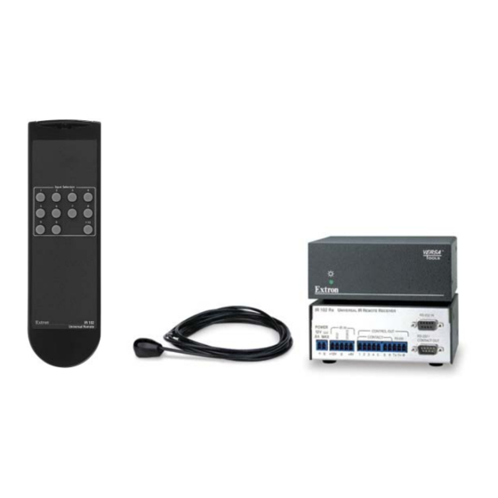
User's Manual
Infrared Remote Control
IR 102 Kit
68-663-01 Rev. D
12 06
Advertisement
Table of Contents

Related Manuals for Extron electronics IR 102


Summary of Contents for Extron electronics IR 102
-
Page 1: Infrared Remote Control
3821 AH Amersfoort, The Netherlands PM Industrial Bldg., Singapore 368363 Chiyoda-ku, Tokyo 102-0082 800.633.9876 714.491.1500 +800.3987.6673 +31.33.453.4040 +800.7339.8766 +65.6383.4400 Japan 68-663-01 Rev. D FAX 714.491.1517 FAX +31.33.453.4050 FAX +65.6383.4664 +81.3.3511.7655 FAX +81.3.3511.7656 www.extron.com 12 06 © 2006 Extron Electronics. All rights reserved. - Page 2 Protección del cables de alimentación • Los cables de alimentación eléctrica se deben protección aislante, que puedan encontrarse dentro use. In no event will Extron Electronics be liable for direct, indirect, or consequential instalar en lugares donde no sean pisados ni apretados por objetos que se puedan de la caja o alojamiento del producto, y que puedan apoyar sobre ellos.
- Page 3 • • • • • • • • • • •...
-
Page 4: Table Of Contents
Appendix A • Specifi cations, Part Numbers, and Accessories ..................A-1 Specifi cations ................A-2 Included Parts ................A-3 Accessories ...................A-3 All trademarks mentioned in this manual are the properties of their respective owners. 68-663-01 Rev. D 12 06 IR 102 Remote Control Kit • Table of Contents... -
Page 5: Installation And Operation
Installation and Operation About the IR 102 Kit Mounting the IR 102 Rx remote receiver Connecting the IR 102 Rx to a Switcher Features and Connections Installing Batteries in the Remote Operation IR 102 Remote Control Kit • Table of Contents... -
Page 6: About The Ir 102 Kit
The following Underwriters Laboratories (UL) requirements The Extron IR 102 Kit is an infrared (IR) remote control kit that pertain to the installation of the IR 102 Rx into or onto a rack. can control a variety of Extron switchers and other devices via RS-232 or contact closure. -
Page 7: Furniture Mounting
Projector mounting procedures differ depending on the mounting kit you use. Mounting using the PMK 100 mini projector mounting kit Projector mount the IR 102 Rx using optional PMK 100 mini Both front false faceplates use 2 screws. Projector mounting kit, part #70-217-01, as follows: Attach the mounting brackets to the IR 102 remote receiver with the provided machine screws. -
Page 8: Mounting Using The Pmk 300 Projector Mounting Kit
PMK 300 multi-product projector projector mounting kit (#70-374-01) mounting kit, part #70-374-01. Follow these steps to mount the IR 102 Rx receiver using the Only VersaTools products and most IP Link products PMK 300: can be mounted using the multi-product projector mounting kit. -
Page 9: Mounting Using The Pmk 350 Projector Mounting Kit
The PMK 300 has a hole in the bottom plate that allows the projector pole to be inserted through the center of the The IR 102 Rx can also be mounted using the PMK 350, as plate, rather than outside of the plate (see the illustration shown below. -
Page 10: Connecting The Ir 102 Rx To A Switcher
Installation and Operation, cont’d If desired, remove the back panel of the PMK 350 and Features and Connections mount an additional IR 102 Rx or other device(s) at the back of the bracket, as described in step 3 on the previous page. - Page 11 Installation and Operation, cont’d The two power cord wires must be kept separate The IR 102 Kit can be used with an Extron MPS 112 while the power supply is plugged in. Remove switcher only when the switcher is in single switch power before continuing.
-
Page 12: Installing Batteries In The Remote Control
Operation The IR 102 handheld remote control is shown below. To select an input using the IR 102 remote control, aim the handheld unit at the IR detector and press the numeric button for the desired input. For switchers with ten or more inputs, press the +10 key to add ten to the input number selected. -
Page 13: Appendix A • Specifi Cations, Part Numbers, And Accessories
Installation and Operation, cont’d IR 102 Remote Control Kit A ppendix A Specifi cations, Part Numbers, and Accessories Specifi cations Included Parts Accessories 1-16 IR 102 Remote Control Kit • Installation and Operation... - Page 14 Specifi cations, Part Numbers, and Accessories Specifi cations Included Parts These items are included in each order for an IR 102 Remote Kit General (part #70-224-01): Carrier frequency ......38 kHz Included parts Replacement Max. IR range (between IR handheld remote control and IR sensor) part number 30 feet (9.1 meters)
-
Page 15: Accessories
Specifi cations, Part Numbers, and Accessories Accessories Part number VersaTools multi-product projector 70-374-01 mounting kit (PMK 300) VersaTools multi-product projector 70-563-02, -03 mounting kit (PMK 350) IR 102 Remote Control Kit • Specifi cations, Part #s, Accessories...