Table of Contents
Advertisement
Quick Links
Extron Electronics, Europe
Extron Electronics, USA
Beeldschermweg 6C, 3821 AH Amersfoort
1230 South Lewis Street, Anaheim, CA 92805
800.633.9876 714.491.1500 FAX 714.491.1517
+31.33.453.4040 FAX +31.33.453.4050
USA
The Netherlands
© 2001 Extron Electronics. All rights reserved.
Extron Electronics, Asia
Extron Electronics Information
135 Joo Seng Rd. #04-01, PM Industrial Bldg.
ExtronWEB
: www.extron.com
™
+65.383.4400 FAX +65.383.4664
ExtronFAX
™
: 714.491.0192
Singapore 368363
24-hour access—worldwide!
User's Manual
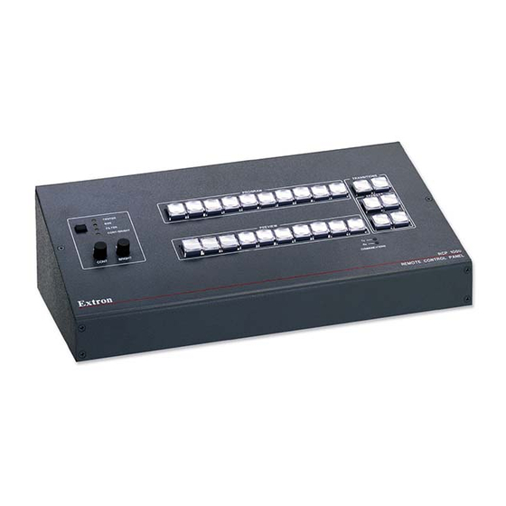
RCP 1000
Remote Control Panel
68-519-01
Printed in the USA
Advertisement
Table of Contents

Related Manuals for Extron electronics RCP 1000


Summary of Contents for Extron electronics RCP 1000
- Page 1 User’s Manual RCP 1000 Remote Control Panel 68-519-01 Extron Electronics, Europe Extron Electronics, Asia Extron Electronics Information Extron Electronics, USA Printed in the USA Beeldschermweg 6C, 3821 AH Amersfoort 135 Joo Seng Rd. #04-01, PM Industrial Bldg. ExtronWEB : www.extron.com 1230 South Lewis Street, Anaheim, CA 92805 ™...
- Page 2 Precautions Safety Instructions • English Extron’s Warranty Warning This symbol is intended to alert the user of important Power sources • This equipment should be operated only from the power source indicated on the product. This equipment is intended to be used with a main operating and maintenance (servicing) instructions power system with a grounded (neutral) conductor.
-
Page 3: Table Of Contents
Implementing an effect ............3-7 Implementing a title ............... 3-7 Appendix • Reference Information ........A-1 Installing a Firmware Update ........... A-2 Specifications ................. A-4 Part Numbers ................A-4 68-519-01 A Printed in the USA 01 01 RCP 1000 • Table of Contents... -
Page 4: Chapter 1 • Introduction
Table of Contents, cont’d RCP 1000 Remote Control Panel Chapter One Introduction Features RCP 1000 • Table of Contents... -
Page 5: Features
The effect buttons allow the switcher operator to choose from among four predefined effects. Installation The RCP 1000 effect presets are the same as the SGS 408 front panel effect presets. Rear Panel Connector Installation Making an RCP Comm Cable RCP 1000 •... -
Page 6: Rear Panel Connector
(attach one pair to pin 3 and the other pair to pin 4). RCP port — One 4-pin XLR connector attaches the RCP 1000 to an SGS 408 seamless switcher. • The cable can be up to 1000 feet (304.8 meters) long. -
Page 7: Chapter 3 • Operation
Installation, cont’d RCP 1000 Remote Control Panel Chapter Three Operation Top Panel Controls Using the Picture Controls Applying a Switch RCP 1000 • Installation... -
Page 8: Top Panel Controls
RCP 1000 is communicating with the SGS 408 unit. When the REMOTE CONTROL PANEL RCP 1000 is transmitting data to the SGS 408, the Tx LED is lit. When the RCP 1000 is receiving data from the SGS 408, the Rx LED is lit. -
Page 9: Using The Picture Controls
Applying other effects adjustment knob. To adjust the horizontal size (width), rotate the right If you are using the RCP 1000 with an ECP 1000, all adjustment knob. transition buttons except the Cut button are disabled. All effect switching must be done through the Filtering an image ECP 1000. -
Page 10: Implementing An Effect
After an effect has been set up on the SGS 408, you can implement it from the RCP 1000. To implement an effect (other • Starting at the center of the screen and moving out to than a title —... -
Page 11: Installing A Firmware Update
Operation, cont’d Press the preview input button to display the preview RCP 1000 Remote Control Panel image on the preview monitor. Press the Effect button that has been programmed for the title. (If the button is already lit, you do not need to press it.) -
Page 12: Installing A Firmware Update
Remove the existing chip and set it aside. Use a standard IC removal tool. Lift the cover from the RCP 1000 unit, and place it next to the unit. Install the new chip: Locate a notch or a printed dot on top of the IC. -
Page 13: Specifications
ECP comm cable – 25’ (7.6 m) 26-434-01 ECP comm cable – 50’ (15.2 m) 26-434-02 SGS 408 Control Program 29-049-01 RCP 1000 User’s Manual 68-519-01 SGS 408 User’s Manual 68-520-01 ECP 1000 User’s Manual 68-518-01 DVI option kit 70-122-01 RCP 1000 • Reference Information...