HP Pavilion dv9000 Maintenance And Service Manual
Hewlett-packard notebook pc maintenance and service guide
Hide thumbs
Also See for Pavilion dv9000:
- Maintenance and service manual (280 pages) ,
- User manual (32 pages) ,
- User manual (14 pages)
Table of Contents
Advertisement
Quick Links
Maintenance and Service
Guide
HP Pavilion dv9000 Notebook PC
Document Part Number:
417615-003
April 2007
This guide is a troubleshooting reference used for maintaining
and servicing the computer. It provides comprehensive
information on identifying computer features, components, and
spare parts; troubleshooting computer problems; and performing
computer disassembly procedures.
Advertisement
Table of Contents
Troubleshooting

Related Manuals for HP Pavilion dv9000


Summary of Contents for HP Pavilion dv9000
- Page 1 Maintenance and Service Guide HP Pavilion dv9000 Notebook PC Document Part Number: 417615-003 April 2007 This guide is a troubleshooting reference used for maintaining and servicing the computer. It provides comprehensive information on identifying computer features, components, and spare parts; troubleshooting computer problems; and performing...
- Page 2 Advanced Micro Devices, Inc. The information contained herein is subject to change without notice. The only warranties for HP products and services are set forth in the express warranty statements accompanying such products and services. Nothing herein should be construed as constituting an additional warranty. HP shall not be liable for technical or editorial errors or omissions contained herein.
- Page 3 Safety warning notice WARNING: To reduce the possibility of heat-related injuries or of Å overheating the computer, do not place the computer directly on your lap or obstruct the computer air vents. Use the computer only on a hard, flat surface. Do not allow another hard surface, such as an adjoining optional printer, or a soft surface, such as pillows or rugs or clothing, to block airflow.
-
Page 4: Table Of Contents
1 Product Description 1.1 Features ........1–2 1.2 Resetting the Computer. - Page 5 Contents 3 Illustrated Parts Catalog 3.1 Serial Number Location ..... . 3–1 3.2 Computer Major Components....3–2 3.3 Display Assembly Components .
- Page 6 Contents 5 Removal and Replacement Procedures 5.1 Serial Number ......5–2 5.2 Disassembly Sequence Chart .
-
Page 7: Specifications
Contents 6 Specifications A Screw Listing B Backup and Recovery in Windows XP C Backup and Recovery in Windows Vista D Display Component Recycling E Connector Pin Assignments F Power Cord Set Requirements Index Maintenance and Service Guide... -
Page 8: Product Description
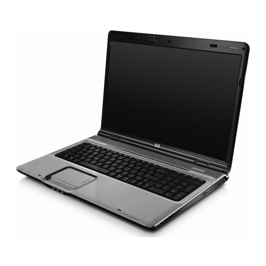
Product Description The HP Pavilion dv9000 Notebook PC offers advanced modularity, Intel® Core™ Duo processors, and extensive multimedia support. HP Pavilion dv9000 Notebook PC Maintenance and Service Guide 1–1... -
Page 9: Features
Product Description 1.1 Features ■ The following processors are available, varying by computer model: ❏ Intel Core Duo T7200 (2.00-GHz) ❏ Intel Core Duo T5600 (1.83-GHz) ❏ Intel Core Duo T5500 (1.66-GHz) ❏ Intel Core Duo T5200 (1.66-GHz)I ❏ Intel Core Duo T2250 (1.66-GHz) ❏... - Page 10 ■ Integrated 10/100/1000 Gigabit Ethernet local area network (LAN) network interface card (NIC) with RJ-45 jack, varying by computer model ■ Integrated high-speed 56K modem with RJ-11 jack ■ Integrated wireless support for Mini Card IEEE 802.11a/b/g and 802.11b/g WLAN devices ■...
-
Page 11: Resetting The Computer
Product Description 1.2 Resetting the Computer If the computer you are servicing has an unknown password, follow these steps to clear the password. These steps also clear CMOS: 1. Prepare the computer for disassembly (refer to “Preparing the Computer For Disassembly,” information). -
Page 12: Power Management
1.3 Power Management The computer comes with power management features that extend battery operating time and conserve power. The computer supports the following power management features: ■ Standby ■ Hibernation ■ Setting customization by the user ■ Hotkeys for setting the level of performance ■... -
Page 13: External Components
Product Description 1.4 External Components The external components on the front of the computer are shown below and described in Table 1-1. Front Components Item Component Power light Battery light 1–6 Table 1-1 Front Components Function On: The computer is on. Blinking: The computer is in standby. - Page 14 (LAN) device and/or a Bluetooth® device, is turned on. Amber: All wireless devices are turned off. Receives a signal from the HP Remote Control. Connects an optional computer headset microphone, stereo array microphone, or monaural microphone.
-
Page 15: Left-Side Components
Product Description The external components on the left side of the computer are shown below and described in Table 1-2. Left-Side Components Item Component Security cable slot S-Video-out jack External monitor port 1–8 Table 1-2 Left-Side Components Function Attaches an optional security cable to the computer. - Page 16 Left-Side Components (Continued) Item Component Expansion port 3 RJ-45 (network) jack RJ-11 (modem) jack HDMI port (select models only) USB ports (2) 1394 port Digital Media Slot light Digital Media Slot Maintenance and Service Guide Table 1-2 Function Connects the computer to an optional expansion product.
- Page 17 Product Description The external components on the right side of the computer are shown below and described in Table 1-3. Right-Side Components 1–10 Maintenance and Service Guide...
-
Page 18: Right-Side Components
Item Component USB ports (2) ExpressCard slot Optical drive Power connector Maintenance and Service Guide Table 1-3 Right-Side Components Function Connect optional USB devices. Supports optional ExpressCard/54 cards. Reads an optical disc. Connects an AC adapter. Product Description 1–1 1... - Page 19 Product Description The computer keyboard components are shown below and described in Table 1-4. Keyboard Components 1–12 Maintenance and Service Guide...
-
Page 20: Keyboard Components
Item Component Function keys caps lock key fn key Windows logo key Windows applications key Arrow keys Numeric keypad keys num lock key Maintenance and Service Guide Table 1-4 Keyboard Components Function Execute frequently used system functions when pressed in combination with the fn key. - Page 21 Product Description The computer top components are shown below and described in Table 1-5. Top Components, Part 1 1–14 Maintenance and Service Guide...
- Page 22 Item Component Integrated camera (select models only) Internal microphones (2, select models only) Speakers (2) Power button Caps lock light Volume mute button Volume scroll zone Num lock light Maintenance and Service Guide Table 1-5 Top Components, Part 1 Function Records video and captures still photos.
- Page 23 Product Description The computer top components are shown below and described in Table 1-6. Top Components, Part 2 1–16 Maintenance and Service Guide...
- Page 24 Item Component Media button DVD button Maintenance and Service Guide Table 1-6 Top Components, Part 2 Function If QuickPlay is not installed and the computer is ■ On, opens the music program or Media menu, which allows you to select a multimedia program.
- Page 25 Product Description Top Components, Part 2 (Continued) Item Component Previous/rewind button Play/pause button Next/fast forward button Stop button 1–18 Table 1-6 Function When a disc is playing in the optical drive: ■ Plays the previous track or chapter, when pressed once. ■...
-
Page 26: Touchpad Components
The computer TouchPad components are shown below and described in Table 1-7. TouchPad Components Item Component TouchPad light TouchPad Left and right TouchPad buttons TouchPad on/off button TouchPad vertical scroll zone Maintenance and Service Guide Table 1-7 Touchpad Components Function Blue: TouchPad is enabled. -
Page 27: Bottom Components
Product Description The external components on the bottom of the computer are shown below and described in Table 1-8. Bottom Components Item Component Battery bay Battery release latch 1–20 Table 1-8 Bottom Components Function Holds the battery. Releases the battery from the battery bay. - Page 28 Bottom Components (Continued) Item Component Optical drive Secondary hard drive bay Primary hard drive bay Vents (6) Memory module compartment Maintenance and Service Guide Table 1-8 Function Reads an optical disc. Holds an optional secondary hard drive. Hold the primary hard drive. Enable airflow to cool internal components.
-
Page 29: Design Overview
Product Description 1.5 Design overview This section presents a design overview of key parts and features of the computer. Refer to to identify replacement parts, and Replacement Procedures,” The system board provides the following device connections: ■ AMD Mobile Turion and Mobile AMD Sempron processors ■... -
Page 30: Troubleshooting
WARNING: Only authorized technicians trained by HP should repair Å this equipment. All troubleshooting and repair procedures are detailed to allow only subassembly-/module-level repair. Because of the complexity of the individual boards and subassemblies, do not attempt to make repairs at the component level or modifications to any printed wiring board. -
Page 31: Navigating And Selecting In The Setup Utility
Troubleshooting 1. To open the Setup Utility, turn on or restart the computer in Windows, and then press to enter setup,” is displayed in the lower-left corner of the screen. 2. Use the arrow keys to select System Configuration > Language, and then press 3. -
Page 32: Restoring Default Settings In The Setup Utility
1. To start the Setup Utility, turn on or restart the computer in Windows, and then press to enter setup,” is displayed in the lower-left corner of the screen. 2. Access the system information by using the Main menu. 3. To close the Setup Utility without changing any settings, use the arrow keys to select Exit >... -
Page 33: Using Advanced Setup Utility Features
Troubleshooting Using Advanced Setup Utility Features This guide describes the Setup Utility features recommended for all users. For more information about the Setup Utility features recommended for advanced users only, refer to the Help and Support Center, which is accessible only when the computer is in Windows. -
Page 34: Setup Utility Menus
■ To close the Setup Utility without saving your changes from the current session: If the Setup Utility menus are not visible, press to the menu display. Then use the arrow keys to select Exit > Exit Discarding Changes, and then press After the Setup Utility closes, the computer restarts in Windows. -
Page 35: Security Menu
Troubleshooting Security Menu Select Administrator password Power-on password System Configuration Menu Select Language Support Embedded WLAN Device Radio Embedded Bluetooth Device (select models only) Enhanced SATA support (select models only) 2–6 Table 2-2 Security Menu To Do This Enter, change, or delete an administrator password. -
Page 36: Diagnostics Menu
System Configuration Menu (Continued) Select Boot Options Diagnostics Menu Select Hard Disk Self Test Maintenance and Service Guide Table 2-3 To Do This Set the following boot options: ■ f10 and f12 Delay (sec.)—Set the delay for the f10 and f12 functions of the Setup Utility in intervals of 5 seconds each (0, 5, 10, 15, 20). -
Page 37: Setup Utility In Windows Vista
Troubleshooting 2.2 Setup Utility in Windows Vista The Setup Utility is a ROM-based information and customization utility that can be used even when your Windows® operating system is not working or will not load. ✎ The fingerprint reader (select models only) does not work when accessing the Setup Utility. - Page 38 5. To set your preferences and exit the Setup Utility, press and then follow the instructions on the screen. Your preferences go into effect when the computer restarts in Windows. Navigating and Selecting in the Setup Utility Because the Setup Utility is not Windows-based, it does not support the TouchPad.
- Page 39 Troubleshooting Restoring Default Settings in the Setup Utility The following procedure explains how to restore the Setup Utility default settings. If the Setup Utility is not already running, begin at step 1. If the Setup Utility is already running, begin at step 2. 1.
-
Page 40: Setup Utility Menus
The “Press <ESC> to change boot order” message that is displayed in the lower-left corner of the screen each time the computer is started or restarted in Windows is the prompt to change the boot order. Closing the Setup Utility You can close the Setup Utility with or without saving changes. -
Page 41: Main Menu
Troubleshooting Main Menu Select System Information Security Menu Select Administrator password Power-on password System Configuration Menu Select Language Support Enhanced SATA support (select models only) 2–12 Table 2-1 Main Menu To Do This ■ View and change the system time and date. ■... - Page 42 Select Boot Options Button Sound (select models only) Video memory up to (select models only) Maintenance and Service Guide Table 2-3 System Configuration Menu To Do This Set the following boot options: ■ f10 and f12 Delay (sec.)—Set the delay for the f10 and f12 functions of the Setup Utility in intervals of 5 seconds each (0, 5, 10, 15, 20).
- Page 43 Troubleshooting Diagnostics Menu Select Hard Disk Self Test Secondary Hard Disk Self Test (select models only) 2–14 Table 2-4 Diagnostics Menu To Do This Run a comprehensive self-test on the hard drive. ✎ On models with two hard drives, this menu option is called the Primary Hard Disk Self Test.
-
Page 44: Troubleshooting Flowcharts
2.3 Troubleshooting Flowcharts Troubleshooting Flowcharts Overview Flowchart Description “Flowchart 2.1—Initial Troubleshooting” “Flowchart 2.2—No Power, Part 1” “Flowchart 2.3—No Power, Part 2” “Flowchart 2.4—No Power, Part 3” “Flowchart 2.5—No Power, Part 4” “Flowchart 2.6—No Video, Part 1” “Flowchart 2.7—No Video, Part 2” “Flowchart 2.8—Nonfunctioning Docking Device (if applicable)”... - Page 45 Troubleshooting Troubleshooting Flowcharts Overview (Continued) Flowchart Description 2.14 “Flowchart 2.14—No OS Loading, Optical Drive” 2.15 “Flowchart 2.15—No Audio, Part 1” 2.16 “Flowchart 2.16—No Audio, Part 2” 2.17 “Flowchart 2.17—Nonfunctioning Device” 2.18 “Flowchart 2.18—Nonfunctioning Keyboard” 2.19 “Flowchart 2.19—Nonfunctioning Pointing Device” 2.20 “Flowchart 2.20—No Network/Modem Connection”...
-
Page 46: Flowchart 2.1—Initial Troubleshooting
Flowchart 2.1—Initial Troubleshooting Begin troubleshooting. Is there power? Beeps, LEDs, or error messages? Is there video? (no boot) Is the OS loading? Is there sound? Maintenance and Service Guide Go to “Flowchart 2.2—No Power, Part 1.” Check LED board, speaker connections. -
Page 47: Flowchart 2.2—No Power, Part
Troubleshooting Flowchart 2.2—No Power, Part 1 No power (power LED is off). Remove from docking device (if applicable). Power up on battery power? Power up on AC power? Power up in docking device? 1. Reseat the power cables in the docking device and at the AC outlet. -
Page 48: Flowchart 2.3—No Power, Part
Flowchart 2.3—No Power, Part 2 Continued from “Flowchart 2.2—No Power, Part 1.” Visually check for debris in battery socket and clean if necessary. Power on? Check battery by recharging it, moving it to another computer, or replacing it. Power on? Done Maintenance and Service Guide Done... -
Page 49: Flowchart 2.4—No Power, Part
Troubleshooting Flowchart 2.4—No Power, Part 3 Continued from “Flowchart 2.3—No Power, Part 2.” Plug directly into AC outlet. Power LED Reseat AC adapter in computer and at power source. Power on? Power outlet active? Replace power cord. Power on? 2–20 Done Done Internal or... -
Page 50: Flowchart 2.5—No Power, Part
Flowchart 2.5—No Power, Part 4 Continued from “Flowchart 2.4—No Power, Part 3.” Open computer. Loose or damaged parts? Close computer and retest. Power on? Done Maintenance and Service Guide Reseat loose components and boards and replace damaged items. Replace the following items (if applicable). Check computer operation after each replacement: 1. -
Page 51: Flowchart 2.6—No Video, Part
Troubleshooting Flowchart 2.6—No Video, Part 1 No video. Docking Device Stand-alone or docking device? Stand-alone Internal or external display*? Internal External Adjust brightness. Video OK? Replace the following one at a time. Test after each replacement. Check for bent pins on cable. Video OK? Done 2–22... -
Page 52: Flowchart 2.7—No Video, Part
Flowchart 2.7—No Video, Part 2 Continued from “Flowchart 2.6—No Video, Part 1.” Remove computer from docking device, if connected. Adjust display brightness. Video OK? Check that computer is properly seated in docking device, for bent pins on cable, and for monitor connection. Video OK? Adjust external monitor display. - Page 53 Troubleshooting Flowchart 2.8—Nonfunctioning Docking Device (if applicable) Nonfunctioning docking device. Reseat power cord in docking device and power outlet. Check voltage setting on docking device. Reset monitor cable connector at docking device. Docking device operating? Remove computer, replace docking device. 2–24 Reinstall computer into...
- Page 54 Flowchart 2.9—No Operating System (OS) Loading No OS loading.* Reseat power cord in docking device and power outlet. *NOTE: Before beginning troubleshooting, always check cable connections, cable ends, and drives for bent or damaged pins. Maintenance and Service Guide No OS loading from hard drive, go to “Flowchart 2.10—No OS Loading, Hard Drive, Part 1.”...
- Page 55 Troubleshooting Flowchart 2.10—No OS Loading, Hard Drive, Part 1 OS not loading from hard drive. Nonsystem disk message? Reseat external hard drive. OS loading? Boot from Check the Setup utility for correct booting order. Boot from hard drive? Done 2–26 Go to “Flowchart 2.11—No OS...
- Page 56 Flowchart 2.1 1—No OS Loading, Hard Drive, Part 2 Continued from “Flowchart 2.10—No OS Loading, Hard Drive, Part 1.” 1. Replace Disc or diskette in 2. Replace system drive? Remove disc or diskette and reboot. Boot from hard drive? Boot 2.13—No OS from diskette drive?
- Page 57 Troubleshooting Flowchart 2.12—No OS Loading, Hard Drive, Part 3 Continued from “Flowchart 2.11—No OS Loading, Hard Drive, Part 2.” System files on hard drive? Virus hard drive? Run SCANDISK and check for bad sectors. Can bad sectors be fixed? Fix bad sectors.
-
Page 58: Flowchart 2.13—No Os Loading, Diskette Drive
Flowchart 2.13—No OS Loading, Diskette Drive OS not loading from diskette drive. Nonsystem disk message? Boot from another device? Diskette drive enabled in the Setup utility? Is diskette drive boot order correct? Change boot priority using 2.17—Nonfunctioning the Setup Utility. Maintenance and Service Guide Reseat diskette drive. -
Page 59: Flowchart 2.14—No Os Loading, Optical Drive
Troubleshooting Flowchart 2.14—No OS Loading, Optical Drive No OS loading from CD-ROM or DVD-ROM drive. Boots from CD or DVD? Reseat drive. 2–30 Disc in drive? Install bootable disc. bootable disc. Done Boots from CD or DVD? Booting from another 2.17—Nonfunctioning device? Reset the computer. -
Page 60: Flowchart 2.15—No Audio, Part
Flowchart 2.15—No Audio, Part 1 No audio. Computer in docking device (if applicable)? Go to “Flowchart 2.16—No Audio, Part 2.” 2.17—Nonfunctioning Maintenance and Service Guide Turn up audio internally or externally. Undock docking device. Go to “Flowchart Device.” Troubleshooting Audio? Internal “Flowchart audio? -
Page 61: Flowchart 2.16—No Audio, Part
Troubleshooting Flowchart 2.16—No Audio, Part 2 Continued from “Flowchart 2.15—No Audio, Part 1.” Audio driver in OS configured? Correct drivers for application? Connect to external speaker. Audio? 2–32 Reload audio drivers. Load drivers and set configuration in OS. Replace audio board and speaker connections... -
Page 62: Flowchart 2.17—Nonfunctioning Device
Flowchart 2.17—Nonfunctioning Device Unplug the nonfunctioning device from the computer and inspect cables and plugs for bent or broken pins Clear CMOS. Reattach device. Close computer, plug in power, and reboot. Device boots properly? Done Maintenance and Service Guide Nonfunctioning device. -
Page 63: Flowchart 2.18—Nonfunctioning Keyboard
Troubleshooting Flowchart 2.18—Nonfunctioning Keyboard Keyboard not operating properly. Connect computer to good external keyboard. External device works? Reseat internal keyboard connector (if applicable). Keyboard operating properly? Done 2–34 Replace system board. Replace internal keyboard or cable. Keyboard operating properly? Replace system board. -
Page 64: Flowchart 2.19—Nonfunctioning Pointing Device
Flowchart 2.19—Nonfunctioning Pointing Device Pointing device not operating properly. Connect computer to good external pointing device. External device works? Reseat internal pointing device connector (if applicable). Pointing device operating properly? Done Maintenance and Service Guide Replace system board. Replace internal pointing device or cable. - Page 65 Troubleshooting Flowchart 2.20—No Network/Modem Connection No network or modem connection. Network or modem jack active? Digital line? NIC/modem configured in OS? Disconnect all power from the computer and open. Reseat NIC/modem (if applicable). 2–36 Replace jack or have jack activated. Connect to nondigital line.
-
Page 66: Illustrated Parts Catalog
Illustrated Parts Catalog This chapter provides an illustrated parts breakdown and a reference for spare part numbers and option part numbers. 3.1 Serial Number Location When ordering parts or requesting information, provide the computer serial number and model number located on the bottom of the computer. -
Page 67: Computer Major Components
Illustrated Parts Catalog 3.2 Computer Major Components Computer Major Components 3–2 Maintenance and Service Guide... - Page 68 ✎ Refer to display assembly internal component spare part number information. Switch cover (includes LED board and cable) For model dv9200 For model dv9000 Power button board (includes power button board cable) Speaker assembly Maintenance and Service Guide Table 3-1 Section 3.3, “Display Assembly Components,”...
- Page 69 Illustrated Parts Catalog Computer Major Components 3–4 Maintenance and Service Guide...
- Page 70 Top cover support trim Top cover (includes TouchPad and TouchPad cable) For model dv9200 For model dv9000 Plastics Kit ExpressCard slot bezel Left hard drive cover (includes 2 captive screws, secured by C-clips) Memory module compartment cover (includes 2 captive screws,...
- Page 71 Illustrated Parts Catalog Computer Major Components 3–6 Maintenance and Service Guide...
- Page 72 Description Wireless switch board (includes wireless switch board cable) Audio board (includes audio board cable and infrared lens) For model dv9200 For model dv9000 Bluetooth module (includes Bluetooth module cable) USB/magnetic board (includes USB/magnetic board cable) For model dv9200 For model dv9000...
- Page 73 Illustrated Parts Catalog Computer Major Components 3–8 Maintenance and Service Guide...
- Page 74 Spare Parts: Computer Major Components (Continued) Item Description Processors (include thermal pad) Intel Core Duo T7200 (2.00-GHz) Intel Core Duo T5600 (1.83-GHz) Intel Core Duo T5500 (1.66-GHz), for dv9200 models Intel Core Duo T5200 (1.66-GHz), for dv9200 models Intel Core Duo T2250 (1.73-GHz), for dv9200 models Intel Core Duo T2300E (1.66-GHz) AMD Turion ML-60 2.0-GHz...
- Page 75 Illustrated Parts Catalog Computer Major Components 3–10 Maintenance and Service Guide...
- Page 76 Spare Parts: Computer Major Components (Continued) Item Description Base enclosures (include wireless switch actuator) For use only with computer models using Intel processors For use only with computer models using AMD processors Batteries 8-cell, 4.4-Ahr for use only with computer models using AMD processors 8-cell, 2.55-Ahr for use only with computer models using Intel processors...
- Page 77 Illustrated Parts Catalog Computer Major Components 3–12 Maintenance and Service Guide...
- Page 78 Spare Parts: Computer Major Components (Continued) Item Description Mini Card modules 802.11a/b/g WLAN Mini Card module for use in the countries or regions listed below. These countries and regions are categorized as most of the world1 (MOW1). Antigua & Barbuda Argentina Australia Bahamas...
- Page 79 Illustrated Parts Catalog Computer Major Components 3–14 Maintenance and Service Guide...
- Page 80 Spare Parts: Computer Major Components (Continued) Item Description Mini Card modules (Continued) 802.11a/b/g WLAN Mini Card module for use in the countries or regions listed below. These countries and regions are categorized as most of the world2 (MOW2). Aruba Austria Azerbaijan Bahrain Belgium...
- Page 81 Illustrated Parts Catalog Computer Major Components 3–16 Maintenance and Service Guide...
- Page 82 Spare Parts: Computer Major Components (Continued) Item Description Mini Card modules (Continued) For use only with models using AMD processors: 802.11a/b/g WLAN Mini Card module for use in the United States and Canada. 802.11a/b/g WLAN Mini Card module for use in the countries or regions listed below: China Ecuador...
- Page 83 Illustrated Parts Catalog Computer Major Components 3–18 Maintenance and Service Guide...
- Page 84 Spare Parts: Computer Major Components (Continued) Item Description Optical drives (include bezel) For use only with computer models using Intel processors: DVD/CD-RW Combo Drive For use only with computer models using AMD processors: DVD/CD-RW Combo Drive For use with all computer models: DVD±RW/R and CD-RW Double-Layer Combo Drive with LightScribe DVD±RW/R and CD-RW Double-Layer Combo...
-
Page 85: Display Assembly Components
Illustrated Parts Catalog 3.3 Display Assembly Components Display Assembly Components Display Assembly Components Spare Part Number Information Item Description Display bezels For use with Dual Lamp display panels with camera For use with Dual Lamp display panels without camera For use with Single Lamp display panels with camera For use with Single Lamp display panels without camera 3–20... - Page 86 Display Assembly Components Spare Part Number Information (Continued) Item Description Display Hinge Kit (includes left and right display hinges) For use with Dual Lamp display panels For use with Single Lamp display panels Display inverters For use with Dual Lamp display panels For use with Single Lamp display panels Camera module Display panels...
-
Page 87: Mass Storage Devices
Illustrated Parts Catalog 3.4 Mass Storage Devices Mass Storage Devices Spare Part Number Information Item Description Hard drives (include bracket and connector) For use only with computer models using Intel processors: 160-GB (5400-rpm) 100-GB (7200-rpm) For use with all computer models 120-GB (5400-rpm) 100-GB (5400-rpm) 80-GB (5400-rpm) -
Page 88: Mass Storage Devices
Spare Part Number Information (Continued) Item Description Hard drives (Continued) Hard drive Bracket Kit (not illustrated) Hard drive bracket rails (APD only) (not illustrated) Hard drive screws (APD only) (not illustrated) Hard drive connector (APD only) (not illustrated) Optical drives For use only with computer models using Intel processors: DVD/CD-RW Combo Drive For use only with computer models using AMD processors:... -
Page 89: Plastics Kit
Illustrated Parts Catalog 3.5 Plastics Kit Plastics Kit Components 3–24 Maintenance and Service Guide... - Page 90 Spare Part Number Information Item Description Plastics Kit Includes: ExpressCard slot bezel Memory module compartment cover (includes 2 captive screws, secured by C-clips) Right hard drive cover (includes 2 captive screws, secured by C-clips) Left hard drive cover (includes 2 captive screws, secured by C-clips) Maintenance and Service Guide Table 3-4 Plastics Kit...
-
Page 91: Cable Kit
Illustrated Parts Catalog 3.6 Cable Kit Cable Kit Components 3–26 Maintenance and Service Guide... - Page 92 Spare Part Number Information Item Description Cable Kit Includes: Audio board cable Display lid switch module cable Bluetooth module cable USB board cable USB/magnetic board cable Maintenance and Service Guide Table 3-5 Cable Kit Illustrated Parts Catalog Spare Part Number 434677-001 3–27...
-
Page 93: Miscellaneous
Illustrated Parts Catalog 3.7 Miscellaneous Description AC adapters HP 90-W PFC AC adapter HP 90-W non-PFC AC adapter Composite S-Video and audio input cable Analog TV tuner Composite S-Video and audio input cable DVB-T TV tuner DVB-T TV tuner antenna... - Page 94 Spare Parts: Miscellaneous (Continued) Description HP Remote Control Remote control, ExpressCard TV tuner, ExpressCard TV tuner antenna Wireless laser mouse Power cords for use with all computer models: Belgium, Europe, Finland, France, Germany, Greece, the Netherlands, Norway, Portugal, Spain, and Sweden...
- Page 95 Illustrated Parts Catalog Spare Parts: Miscellaneous (Continued) Description Screw Kit (include the following screws; refer to A, “Screw Listing,” for more information on screw specifications and usage) For use only with computer models using Intel processors For use only with computer models using AMD processors ■...
-
Page 96: Sequential Part Number Listing
Power cord for use in Israel 394279-D01 Power cord for use in Argentina 394279-D61 Power cord for use in India 405527-001 HP Backpack 407159-001 802.11a/b/g WLAN Mini Card module for use in the United States and Canada. Maintenance and Service Guide Table 3-7 Illustrated Parts Catalog 3–31... - Page 97 802.11a/b/g WLAN Mini Card module for use in the countries and regions listed below: China Ecuador Haiti Honduras 407313-001 HP Remote Control 407674-001 802.11a/b/g WLAN Mini Card module for use in the MOW1 countries and regions listed below: Antigua & Barbuda Argentina...
- Page 98 Spare Parts: Sequential Part Number Listing (Continued) Spare Part Number Description 407674-002 802.11a/b/g WLAN Mini Card module for use in the MOW2 countries and regions listed below: Aruba Austria Azerbaijan Bahrain Belgium Bermuda Bulgaria Cayman Islands Columbia Croatia Cyprus The Czech Republic Denmark Egypt...
- Page 99 431391-001 Display inverter for use with Single Lamp display panels 431436-001 RTC battery (includes 2-sided tape) 432309-001 HP 90W PFC AC adapter 432945-001 System board for use only with discrete computer models using AMD processors 432946-001 17.0-inch, WXGA+, TFT Single Lamp display assembly with...
- Page 100 Spare Parts: Sequential Part Number Listing (Continued) Spare Part Number Description 432948-001 17.0-inch, WXGA+, TFT Dual Lamp display assembly with BrightView for use with full-featured computer models (includes camera, camera cable, microphones, wireless antenna transceivers, and cables) 432949-001 17.0-inch, WXGA+, TFT Single Lamp display assembly with BrightView (includes microphones, wireless antenna transceivers, and cables) 432950-001...
- Page 101 DVD±RW/R and CD-RW Double-Layer Combo Drive with LightScribe 432974-001 8-cell, 4.4-Ahr battery 432977-001 Top cover (includes TouchPad and TouchPad cable) for model dv9000 432979-001 Switch cover (includes LED board and cable) for model dv9000 432978-001 Top cover support trim 3–36...
- Page 102 432985-001 Power connector assembly (includes power connector assembly cable and power connector assembly bracket) 432986-001 Audio board (includes audio board cable and infrared lens) for model dv9000 432987-001 Power button board (includes power button board cable) 432988-001 ExpressCard assembly 432989-001...
- Page 103 512-MB memory module, PC-5300, 667-MHz, 1-DIMM for use only with models using Intel processors 434742-001 1024-MB memory module, PC-5300, 667-MHz, 1-DIMM for use only with models using Intel processors 435743-001 HP Remote Control 435659-001 Hard Drive Hardware Kit 435836-001 USB travel mouse 3–38...
- Page 104 Spare Parts: Sequential Part Number Listing (Continued) Spare Part Number Description 436067-001 Display bezel for use with Single Lamp display panels without camera 436068-001 Display bezel for use with Dual Lamp display panels without camera 436069-001 IAMD Turion ML-60 2.0-GHz processor 436070-001 Immobile AMD Sempron 3500+ (1.8-GHz) processor 436157-001...
- Page 105 Illustrated Parts Catalog Spare Parts: Sequential Part Number Listing (Continued) Spare Part Number Description 439129-001 Infrared emitter 439130-001 TV tuner, ExpressCard 439131-001 TV tuner antenna 439254-001 Remote control, ExpressCard (EMEA) 441541-001 Keyboard for use in the United States 441541-031 Keyboard for use in the United Kingdom 441541-041 Keyboard for use in Germany 441541-051...
-
Page 106: Removal And Replacement Preliminaries
Removal and Replacement This chapter provides essential information for proper and safe removal and replacement service. 4.1 Tools Required You will need the following tools to complete the removal and replacement procedures: ■ Magnetic screwdriver ■ Phillips P0 and P1 screwdrivers ■... -
Page 107: Service Considerations
Removal and Replacement Preliminaries 4.2 Service Considerations The following sections include some of the considerations that you should keep in mind during disassembly and assembly procedures. ✎ As you remove each subassembly from the computer, place the subassembly (and all accompanying screws) away from the work area to prevent damage. -
Page 108: Preventing Damage To Removable Drives
4.3 Preventing Damage to Removable Drives Removable drives are fragile components that must be handled with care. To prevent damage to the computer, damage to a removable drive, or loss of information, observe the following precautions: ■ Before removing or inserting a hard drive, shut down the computer. -
Page 109: Preventing Electrostatic Damage
Removal and Replacement Preliminaries 4.4 Preventing Electrostatic Damage Many electronic components are sensitive to electrostatic discharge (ESD). Circuitry design and structure determine the degree of sensitivity. Networks built into many integrated circuits provide some protection, but in many cases, the discharge contains enough power to alter device parameters or melt silicon junctions. -
Page 110: Packaging And Transporting Precautions
4.5 Packaging and Transporting Precautions Use the following grounding precautions when packaging and transporting equipment: ■ To avoid hand contact, transport products in static-safe containers, such as tubes, bags, or boxes. ■ Protect all electrostatic-sensitive parts and assemblies with conductive or approved containers or packaging. ■... -
Page 111: Workstation Precautions
Removal and Replacement Preliminaries 4.6 Workstation Precautions Use the following grounding precautions at workstations: ■ Cover the workstation with approved static-shielding material (refer to ■ Use a wrist strap connected to a properly grounded work surface and use properly grounded tools and equipment. ■... -
Page 112: Grounding Equipment And Methods
4.7 Grounding Equipment and Methods Grounding equipment must include either a wrist strap or a foot strap at a grounded workstation. ■ When seated, wear a wrist strap connected to a grounded system. Wrist straps are flexible straps with a minimum of one megohm ±10% resistance in the ground cords. -
Page 113: Typical Electrostatic Voltage Levels
Removal and Replacement Preliminaries Table 4-1 shows how humidity affects the electrostatic voltage levels generated by different activities. Typical Electrostatic Voltage Levels Event Walking across carpet Walking across vinyl floor Motions of bench worker Removing DIPS from plastic tube Removing DIPS from vinyl tray Removing DIPS from Styrofoam Removing bubble pack from PCB Packing PCBs in foam-lined box... -
Page 114: Removal And Replacement Procedures
Removal and Replacement Procedures This chapter provides removal and replacement procedures. There are as many as 109 screws, in 11 different sizes, that must be removed, replaced, or loosened when servicing the computer. Make special note of each screw size and location during removal and replacement. -
Page 115: Serial Number
Removal and Replacement Procedures 5.1 Serial Number Report the computer serial number to HP when requesting information or ordering spare parts. The serial number is located on the bottom of the computer. Serial Number Location 5.2 Disassembly Sequence Chart Use the chart below to determine the section number to be referenced when removing computer components. - Page 116 Disassembly Sequence Chart (Continued) Section Description Hard Drive Computer Feet Memory Module RTC Battery Mini Card Module Ä To prevent an unresponsive system and the display of a warning message, install only a Mini Card device authorized for use in your computer by the governmental agency that regulates wireless devices in your country or region.
- Page 117 Removal and Replacement Procedures Disassembly Sequence Chart (Continued) Section Description 5.14 Display Assembly Display bezel Camera module Display inverter Display panel Display hinges Display hinge covers Wireless antenna transceivers Microphones Camera cable 5.15 Top Cover 5.16 Wireless Switch Board 5.17 Audio Board 5.18 Bluetooth Module...
-
Page 118: Preparing The Computer For Disassembly
5.3 Preparing the Computer For Disassembly Before you begin any removal or installation procedures: 1. Shut down the computer. If you are unsure whether the computer is off or in hibernation, turn the computer on, and then shut it down through the operating system. 2. - Page 119 Removal and Replacement Procedures b. Slide and hold the battery release latch 1 to the left. (The front edge of the battery disengages from the computer.) c. Lift the front edge of the battery 2 and swing it back. d. Remove the battery. Removing the Battery Reverse the above procedure to install the battery.
-
Page 120: Hard Drive
5.4 Hard Drive Hard Drive Spare Part Number Information Hard drives (include bracket and connector) For use only with computer models using Intel processors: 160-GB (5400-rpm) 100-GB (7200-rpm) For use with all computer models (all 5400 rpm): 120-GB 100-GB 80-GB Hard Drive Bracket Kit Maintenance and Service Guide Removal and Replacement Procedures... - Page 121 Removal and Replacement Procedures 1. Prepare the computer for disassembly (refer to 2. Loosen the two captive Phillips PM2.0×5.0 screws 1 that secure each hard drive cover to the computer. 3. Lift the right side of the cover 2 and swing it to the left. 4.
- Page 122 Removal and Replacement Procedures 5. Use the mylar tab 1 to lift the hard drive 2 until it disconnects from the computer. 6. Remove the hard drive from the hard drive bay. Removing the Hard Drive Maintenance and Service Guide 5–9...
- Page 123 Removal and Replacement Procedures 7. Remove the four Phillips PM3.0×3.0 screws 1 that secure the hard drive bracket to the hard drive. 8. Lift the bracket 2 straight up to remove it from the hard drive. ✎ The hard drive bracket and the screws used to secure the bracket to the hard drive are included in the Hard Drive Bracket Kit, spare part number 434106-001.
-
Page 124: Computer Feet
Removal and Replacement Procedures 5.5 Computer Feet The computer feet are adhesive-backed rubber pads. The feet are included in the Rubber Feet Kit, spare part number 432982-001. The feet attach to the base enclosure in the locations illustrated below. Computer Feet Locations Maintenance and Service Guide 5–1 1... -
Page 125: Memory Module
Removal and Replacement Procedures 5.6 Memory Module Memory Module Spare Part Number Information Memory modules, PC-5300, 667-MHz, 1-DIMM For use only with models using Intel processors: 1024-MB 512-MB For use only with models using AMD processors: 1024-MB 512-MB 256-MB 1. Prepare the computer for disassembly (refer to 5–12 434742-001 434741-001... - Page 126 2. Loosen the two captive Phillips PM2.0×5.0 screws 1 that secure the memory module compartment cover to the computer. 3. Lift the front of the memory module compartment cover 2, and then swing it back. 4. Remove the memory module compartment cover. ✎...
- Page 127 Removal and Replacement Procedures 5. Spread the retaining tabs 1 on each side of the memory module socket to release the memory module. (The edge of the module opposite the socket rises away from the computer.) 6. Slide the module 2 away from the socket at an angle. ✎...
-
Page 128: Rtc Battery
5.7 RTC Battery RTC Battery Spare Part Number Information RTC battery (includes 2-sided tape) 1. Prepare the computer for disassembly (refer to 2. Remove the memory module compartment cover (Section 3. Disconnect the RTC battery cable 1 from the system board. 4. -
Page 129: Mini Card Module
Removal and Replacement Procedures 5.8 Mini Card Module Spare Part Number Information For use only with models using Intel processors: 802.11a/b/g WLAN Mini Card module for use in the MOW1 countries and regions listed below: Antigua & Canada Barbuda Chile Argentina Dominican Australia... - Page 130 Spare Part Number Information (Continued) 802.11a/b/g WLAN Mini Card module for use in the ROW countries and regions listed below: China Honduras Ecuador Pakistan Haiti Peru 802.11b/g WLAN Mini Card module for use in Costa Rica, Israel, Kuwait, Thailand, UAE, Ukraine. 802.11a/b/g WLAN Mini Card module for use only in Japan For use only with models using AMD processors: 802.11a/b/g WLAN Mini Card module for use in...
- Page 131 Removal and Replacement Procedures 3. Make note of which wireless antenna cable is attached to which antenna clip on the Mini Card module before disconnecting the cables. Then disconnect the cables 1 from the module. 4. Remove the two Phillips PM2.0×11.0 screws 2 that secure the Mini Card module to the computer.
-
Page 132: Optical Drive
5.9 Optical Drive Optical Drive Spare Part Number Information For use only with computer models using Intel processors: DVD/CD-RW Combo Drive For use only with computer models using AMD processors: DVD/CD-RW Combo Drive For use with all computer models DVD±RW/R and CD-RW Double-Layer Combo Drive with LightScribe DVD±RW/R and CD-RW Double-Layer Combo Drive 1. - Page 133 Removal and Replacement Procedures 2. Remove the Phillips PM2.5×8.0 screw 1 that secures the optical drive to the computer. 3. Insert a thin tool, such as a paper clip 2, into the media tray release hole. (The optical drive media tray releases from the optical drive.) 4.
- Page 134 6. Position the optical drive with the optical drive bracket toward you. 7. Remove the two Phillips PM2.0×3.0 screws 1 that secure the optical drive bracket to the optical drive. 8. Remove the optical drive bracket 2. Removing the Optical Drive Bracket Reverse the above procedure to reassemble and install the optical drive.
-
Page 135: Switch Cover
Removal and Replacement Procedures 5.10 Switch Cover Switch Cover Spare Part Number Information Switch cover (includes LED board and LED board cable), for model dv9000 Switch cover (includes LED board and LED board cable), for model dv9200 1. Prepare the computer for disassembly 2. - Page 136 Removal and Replacement Procedures 5. Turn the computer display-side up with the front toward you. 6. Open the computer as far as possible. 7. Lift the rear edge of the switch cover and swing it forward until it rests on the keyboard. Releasing the Switch Cover Maintenance and Service Guide 5–23...
- Page 137 Removal and Replacement Procedures 8. Release the zero insertion force (ZIF) connector 1 to which the LED board cable is connected and disconnect the cable 2 from the LED board. 9. Remove the switch cover. Disconnecting the LED Board Cable Reverse the above procedure to install the switch cover.
-
Page 138: Keyboard
5.1 1 Keyboard Keyboard Spare Part Number Information For use in the following countries and regions: Belgium Denmark, Finland, Norway, and Sweden France French Canada Germany Greece Israel Italy Japan 1. Prepare the computer for disassembly 2. Remove the switch cover Maintenance and Service Guide Removal and Replacement Procedures 441541-A41... - Page 139 Removal and Replacement Procedures 3. Remove the Phillips PM2.5×7.0 screw that secures the keyboard to the computer. Removing the Keyboard Screw, Part 1 5–26 Maintenance and Service Guide...
- Page 140 4. Turn the computer display-side up with the front panel toward you. 5. Open the computer as far as possible. 6. Remove the three silver Phillips PM2.5×5.0 screws that secure the keyboard to the computer. Removing the Keyboard Screws, Part 2 Maintenance and Service Guide Removal and Replacement Procedures 5–27...
- Page 141 Removal and Replacement Procedures 7. Lift the rear edge of the keyboard 1 until it rests at an angle. 8. Slide the keyboard 2 back to disengage the tabs on the front edge of the keyboard from the top cover. 9.
- Page 142 10. Release the ZIF connector 1 to which the keyboard cable is connected and disconnect the keyboard cable 2 from the system board. Disconnecting the Keyboard Cable 11. Remove the keyboard. Reverse the above procedure to install the keyboard. Maintenance and Service Guide Removal and Replacement Procedures 5–29...
-
Page 143: Speaker Assembly
Removal and Replacement Procedures 5.12 Speaker Assembly Speaker Assembly Spare Part Number Information Speaker assembly 1. Prepare the computer for disassembly 2. Remove the switch cover 3. Remove the keyboard 4. Disconnect the speaker assembly cable 1 from the power button board. - Page 144 6. Remove the two black Phillips PM2.5×5.0 screws 1 that secure the speaker assembly to the computer. 7. Remove the speaker assembly 2. Removing the Speaker Assembly Reverse the above procedure to install the speaker assembly. Maintenance and Service Guide Removal and Replacement Procedures 5–31...
-
Page 145: Power Button Board
Removal and Replacement Procedures 5.13 Power Button Board Power Button Board Spare Part Number Information Power button board (includes power button board cable) 1. Prepare the computer for disassembly 2. Remove the switch cover 3. Remove the keyboard 4. Disconnect the following cables from the power button board: 1 Display lid switch module cable 2 Microphone cable... - Page 146 6. Remove the silver Phillips PM2.5×5.0 screw 1 that secures the power button board to the computer. 7. Remove the power button board 2. Removing the Power Button Board Reverse the above procedure to install the power button board. Maintenance and Service Guide Removal and Replacement Procedures 5–33...
-
Page 147: Display Assembly
Removal and Replacement Procedures 5.14 Display Assembly Display Assembly Spare Part Number Information For use with full-featured computer models (includes camera, camera cable, and microphones) 17.0-inch, SXGA+, TFT Single Lamp with BrightView 17.0-inch, WXGA+, TFT Single Lamp with BrightView 17.0-inch, WXGA+, TFT Dual Lamp with BrightView For use with de-featured computer models (includes microphones) 17.0-inch, SXGA+, TFT Single Lamp with BrightView... - Page 148 2. Close the computer. 3. Turn the computer upside down with the rear panel toward you. 4. Remove the two Phillips PM2.5×8.0 screws that secure the display assembly to the computer. Removing the Display Assembly Screws Maintenance and Service Guide Removal and Replacement Procedures 5–35...
- Page 149 Removal and Replacement Procedures 5. Turn the computer display-side up with the front toward you. 6. Open the computer to an upright position. 7. Disconnect the display cable 1 from the system board and the microphone cable 2 from the power button board. 8.
- Page 150 CAUTION: Support the display assembly when removing the following Ä screws. Failure to support the display assembly can result in damage to the display assembly and other computer components. 10. Remove the two Phillips PM2.5×8.0 screws 1 and the two silver Phillips PM2.5×5.0 screws 2 that secure the display assembly to the computer.
- Page 151 Removal and Replacement Procedures 12. Remove the following: 1 Three rubber screw covers on the display bezel top edge 2 Two rubber screw covers on the display bezel bottom edge 3 Five Phillips PM2.5×8.0 screws ✎ The display rubber screw covers are included in the Display Screw Kit, spare part number 432967-001.
-
Page 152: Display Assembly Subcomponents
Display Assembly Subcomponents Spare Part Number Information Display bezels For use with Dual Lamp display panels with camera For use with Dual Lamp display panels without camera For use with Single Lamp display panels with camera For use with Single Lamp display panels without camera 13. - Page 153 Removal and Replacement Procedures Display Assembly Subcomponents Spare Part Number Information Camera module ✎ The camera module is secured to the display enclosure by a 2-sided adhesive pad. Apply removal force to the middle of the module to remove it. 15.
- Page 154 Display Assembly Subcomponents Spare Part Number Information Display inverters For use with Dual Lamp display panels For use with Single Lamp display panels 17. Remove the inverter 1 from the display enclosure. 18. Disconnect the display cable 2 and the backlight cable 3 from the display inverter.
- Page 155 Removal and Replacement Procedures Display Assembly Subcomponents Spare Part Number Information Display panels 17.0-inch, WXGA+, TFT Dual Lamp display panel with BrightView 17.0-inch, SXGA+, TFT Single Lamp display panel with BrightView 17.0-inch, WXGA+, TFT Single Lamp display panel with BrightView 19.
- Page 156 Display Assembly Subcomponents Spare Part Number Information Display Hinge Kits For use with Dual Lamp display panels For use with Single Lamp display panels Display hinge covers 21. Remove the two Phillips PM2.0×3.0 screws 1 that secure each display hinge to the display enclosure. 22.
- Page 157 Removal and Replacement Procedures Display Assembly Subcomponents Spare Part Number Information Wireless antenna transceivers and cables 24. If it is necessary to replace the wireless antenna transceivers and cables, remove the two Phillips PM2.0×4.0 screws 1 that secure each transceiver to the display enclosure. 25.
- Page 158 Display Assembly Subcomponents Spare Part Number Information Microphones 28. If it is necessary to replace the microphones and cables, release the retention tabs 1 built into the display enclosure that secure the microphone cables to the display enclosure. 29. Remove the microphone receivers 2 from the clips in the display enclosure.
- Page 159 Removal and Replacement Procedures Display Assembly Subcomponents Spare Part Number Information Display Cable Kit (includes camera cable) 31. If it is necessary to replace the camera cable, release the retention tabs 1 built into the display enclosure that secure the camera cable to the display enclosure. 32.
-
Page 160: Top Cover
5.15 Top Cover Top Cover Spare Part Number Information Top cover (includes TouchPad and TouchPad cable) for use with model dv9000 Top cover (includes TouchPad and TouchPad cable) for use with dv9200 1. Prepare the computer for disassembly remove the following components: ❏... - Page 161 Removal and Replacement Procedures 2. Turn the computer upside down with the front toward you. 3. Remove the eight Phillips PM2.5×8.0 screws that secure the top cover to the computer. Removing the Top Cover Screws, Part 1 5–48 Maintenance and Service Guide...
- Page 162 Removal and Replacement Procedures 4. Remove the four silver Phillips PM2.5×5.0 screws that secure the top cover to the computer. Removing the Top Cover Screws, Part 2 Maintenance and Service Guide 5–49...
- Page 163 Removal and Replacement Procedures 5. Turn the computer right-side up with the front toward you. 6. Disconnect the power button board cable 1 and the LED board cable 2 from the low insertion force (LIF) connectors to which they are connected. 7.
- Page 164 Removal and Replacement Procedures 8. Remove the five Phillips PM2.5×8.0 screws 1 and the silver Phillips PM2.5×5.0 screw 2 that secures the top cover to the computer. Removing the Top Cover Screws, Part 3 Maintenance and Service Guide 5–51...
- Page 165 Removal and Replacement Procedures 9. Lift the rear edge of the top cover until it disengages from the computer, and remove the top cover. Removing the Top Cover Reverse the above procedure to install the top cover. 5–52 Maintenance and Service Guide...
-
Page 166: Wireless Switch Board
5.16 Wireless Switch Board Wireless Switch Board Spare Part Number Information Wireless switch board 1. Prepare the computer for disassembly remove the following components: ❏ Hard drive ❏ Optical drive ❏ Switch cover ❏ Keyboard ❏ Speaker assembly ❏ Display assembly ❏... - Page 167 Removal and Replacement Procedures 2. Release the ZIF connector 1 to which the wireless switch board cable is connected and disconnect the wireless switch board cable 2 from the system board. Removing the Wireless Switch Board 5–54 Maintenance and Service Guide...
- Page 168 3. Remove the two silver Phillips PM2.5×5.0 screws 1 that secure the wireless switch board to the base enclosure. 4. Remove the wireless switch board 2. Removing the Wireless Switch Board Reverse the above procedure to install the wireless switch board. Maintenance and Service Guide Removal and Replacement Procedures 5–55...
-
Page 169: Audio Board
5.17 Audio Board Audio Board Spare Part Number Information Audio board (includes audio board cable and infrared lens) for use with dv9000 Audio board (includes audio board cable and infrared lens) for use with dv9200 1. Prepare the computer for disassembly remove the following components: ❏... - Page 170 2. Remove the silver Phillips PM2.5×5.0 screw 1 that secures the audio board to the computer. 3. Slide the audio board 2 back to disengage the audio connectors from the base enclosure. 4. Remove the audio board 3. 5. Disconnect the audio board cable 4 from the system board. ✎...
-
Page 171: Bluetooth Module
Removal and Replacement Procedures 5.18 Bluetooth Module Bluetooth Module Spare Part Number Information Bluetooth module (includes Bluetooth module cable) 1. Prepare the computer for disassembly remove the following components: ❏ Hard drive ❏ Optical drive ❏ Switch cover ❏ Keyboard ❏... - Page 172 2. Disconnect the Bluetooth module cable 1 from the system board. ✎ The Bluetooth module cable is included with the Bluetooth module spare part kit and is also included in the Cable Kit, spare part number 434677-001. 3. Route the Bluetooth module cable 2 under the system board. 4.
-
Page 173: Usb/Magnetic Board
Removal and Replacement Procedures 5.19 USB/Magnetic Board USB/Magnetic Board Spare Part Number Information USB/magnetic board (includes USB/magnetic board cable) for use with dv9000 USB/magnetic board (includes USB/magnetic board cable) for use with dv9200 1. Prepare the computer for disassembly remove the following components: ❏... - Page 174 2. Disconnect the USB/magnetic board cable 1 from the ExpressCard assembly. ✎ The USB/magnetic board cable is included with the USB/magnetic board spare part kit and is also included in the Cable Kit, spare part number 434677-001. 3. Remove the silver Phillips PM2.5×5.0 screw 2 that secures the USB/magnetic board to the base enclosure.
-
Page 175: Expresscard Assembly
Removal and Replacement Procedures 5.20 ExpressCard Assembly ExpressCard Assembly Spare Part Number Information ExpressCard assembly 1. Prepare the computer for disassembly remove the following components: ❏ Hard drive ❏ Optical drive ❏ Switch cover ❏ Keyboard ❏ Speaker assembly ❏ Display assembly ❏... - Page 176 2. Push in on the ExpressCard slot bezel 1 to release the bezel from the ExpressCard slot. 3. Remove the ExpressCard slot bezel 2. ✎ The ExpressCard slot bezel is included in the Plastics Kit, spare part number 432981-001. Removing the ExpressCard Slot Bezel Maintenance and Service Guide Removal and Replacement Procedures 5–63...
- Page 177 Removal and Replacement Procedures 4. Remove the four silver Phillips PM2.5×5.0 screws 1 that secure the ExpressCard assembly to the system board. 5. Slide the ExpressCard assembly 2 to the right to disconnect it from the system board. 6. Remove the ExpressCard assembly 3. Removing the ExpressCard Assembly Reverse the above procedure to install the ExpressCard assembly.
-
Page 178: Top Cover Support Trim
5.21 Top Cover Support Trim Top Cover Support Trim Spare Part Number Information Top cover support trim 1. Prepare the computer for disassembly remove the following components: ❏ Hard drive ❏ Optical drive ❏ Switch cover ❏ Keyboard ❏ Speaker assembly ❏... - Page 179 Removal and Replacement Procedures 2. Turn the computer upside down with the front toward you. 3. Remove the four Phillips PM2.5×8.0 screws that secure the top cover support trim to the computer. Removing the Top Cover Support Trim Screws 5–66 Maintenance and Service Guide...
- Page 180 4. Turn the computer right-side up with the front toward you. 5. Remove the Phillips PM2.5×8.0 screw 1 that secures the top cover support trim to the computer. 6. Remove the top cover support trim 2. Removing the Top Cover Support Trim Reverse the above procedure to install the top cover support trim.
-
Page 181: Display Lid Switch Module
Removal and Replacement Procedures 5.22 Display Lid Switch Module Display Lid Switch Module Spare Part Number Information Display lid switch module 1. Prepare the computer for disassembly remove the following components: ❏ Hard drive ❏ Optical drive ❏ Switch cover ❏... - Page 182 2. Remove the display lid switch module by firmly pulling it off the fan/heat sink assembly. ✎ The display lid switch module is secured to the fan/heat sink assembly by 2-sided tape. Apply removal force to the middle of the module to remove it. Removing the Display Lid Switch Module ✎...
-
Page 183: Power Connector Assembly
Removal and Replacement Procedures 5.23 Power Connector Assembly Power Connector Assembly Spare Part Number Information Power connector assembly (includes power connector assembly cable and power connector assembly bracket) USB board 1. Prepare the computer for disassembly remove the following components: ❏... - Page 184 2. Remove the two silver Phillips PM2.5×5.0 screws 1 that secure the power connector assembly bracket to the computer. 3. Remove the power connector assembly bracket 2. Removing the Power Connector Assembly Bracket Maintenance and Service Guide Removal and Replacement Procedures 5–71...
- Page 185 Removal and Replacement Procedures 4. Remove the silver Phillips PM2.5×5.0 screw 1 that secures the USB board to the computer. 5. Remove the USB board 2. 6. Disconnect the USB board cable 3 from the USB board and remove the cable from the clips 4 in the base enclosure. ✎...
- Page 186 7. Remove the black Phillips PM2.5×5.0 screw 1 that secures the power connector assembly to the computer. 8. Remove the power connector assembly 2 from its location in the base enclosure. Releasing the Power Connector Assembly Reverse the above procedure to install the USB board and power connector assembly.
-
Page 187: System Board
Removal and Replacement Procedures 5.24 System Board System Board Spare Part Number Information For use with only computer models using Intel processors: G73 (includes 512-MB of video RAM) G73M (includes 256-MB of video RAM) G73 (includes 512 MB of video RAM) - for Germany only For use only with UMA computer models using AMD processors For use only with discrete computer models using... - Page 188 ❏ Speaker assembly ❏ Display assembly ❏ Top cover ❏ Wireless switch board ❏ Audio board ❏ USB/magnetic board ❏ Top cover support trim ❏ USB board ❏ Power connector assembly 2. Turn the computer upside down with the front toward you. 3.
- Page 189 Removal and Replacement Procedures 4. Remove the three Phillips PM2.5×8.0 screws 1 and the three silver Phillips PM2.5×5.0 screws 2 that secure the system board to the base enclosure. Removing the System Board Screws, Part 2 5–76 Maintenance and Service Guide...
- Page 190 5. Lift the right side of the system board 1 until it rests at an angle. 6. Remove the optical drive connector board 2. ✎ The optical drive connector board is available using spare part number 432992-001. 7. Slide the system board 3 to the right until the connectors on the left side of the system board disengage from the base enclosure.
- Page 191 Removal and Replacement Procedures 9. If it is necessary to replace the power connector assembly or the USB board cable, turn the system board upside down with the front toward you. 10. Disconnect the power connector assembly cable 1 and the USB board cable 2 from the system board.
-
Page 192: Fan/Heat Sink Assembly
5.25 Fan/Heat Sink Assembly Fan/Heat Sink Assembly Spare Part Number Information For use only with computer models using Intel processors For use only with computer models using AMD processors ✎ When replacing the fan/heat sink assembly, be sure the display lid switch module is removed from the defective fan/heat sink assembly and installed on the replacement fan/heat sink assembly. - Page 193 Removal and Replacement Procedures 2. Turn the system board upside down with the expansion port and external monitor port toward you. 3. Disconnect the fan cable 1 from the system board. 4. Loosen the four captive Phillips PM2.5×6.0 screws 2 that secure the fan/heat sink assembly to the system board.
- Page 194 Removal and Replacement Procedures ✎ The thermal pads and thermal paste should be thoroughly cleaned from the surfaces of the fan/heat sink assembly 1, 2, and 3, the system board components 4 and 6, and the processor 5 each time the fan/heat sink assembly is removed. Thermal pads and thermal paste should be installed on all surfaces before the fan/heat sink assembly is reinstalled.
- Page 195 Removal and Replacement Procedures 6. Loosen the three captive silver Phillips PM2.5×5.0 screws 1 that secure the heat sink to the system board. 7. Remove the heat sink 2. Removing the Heat Sink 5–82 Maintenance and Service Guide...
- Page 196 Removal and Replacement Procedures ✎ The thermal pads and thermal paste should be thoroughly cleaned from the surfaces of the heat sink 1, 2, and 3 and the system board components 4, 5, and 6, each time the heat sink is removed.
-
Page 197: Processor
Removal and Replacement Procedures 5.26 Processor Processor Spare Part Number Information Processors (include thermal pads and thermal paste) Intel Core Duo T7200 (2.00-GHz) Intel Core Duo T5600 (1.83-GHz) Intel Core Duo T5500 (1.66-GHz), for dv9200 models Intel Core Duo T5200 (1.66-GHz), for dv9200 models Intel Core Duo T2250 (1.66-GHz), for dv9200 models Intel Core Duo T2300E (1.66-GHz) Intel Core Duo T5200 (1.66-GHz) - Page 198 ❏ Switch cover ❏ Keyboard ❏ Speaker assembly ❏ Display assembly ❏ Top cover ❏ Wireless switch board ❏ Audio board ❏ USB/magnetic board ❏ Top cover support trim ❏ USB board ❏ Power connector assembly ❏ System board ❏ Fan/heat sink assembly Maintenance and Service Guide Removal and Replacement Procedures...
- Page 199 Removal and Replacement Procedures 2. Turn the processor locking screw 1 one-half turn counterclockwise until you hear a click. 3. Lift the processor 2 straight up and remove it. ✎ The gold triangle 3 on the processor should be aligned with the triangle icon 4 embossed on the processor socket when you install the processor.
- Page 200 This chapter provides physical and performance specifications. Dimensions With Dual Lamp Display Length Width Height (varies front to rear) With Single Lamp Display Length Width Height (varies front to rear) Weight (varies by configuration) With Dual Lamp Display With Single Lamp Display Second hard drive adds: Camera adds: Stand-alone power requirements...
- Page 201 Specifications Temperature Operating* Nonoperating Relative humidity (noncondensing) Operating Nonoperating Maximum altitude (unpressurized) Operating (14.7 to 10.1 psia) Nonoperating (14.7 to 4.4 psia) Shock Operating Nonoperating Random Vibration Operating Nonoperating *Applicable product safety standards specify thermal limits for plastic surfaces. The computer operates well within this range of temperatures. 6–2 Table 6-1 Computer (Continued)
- Page 202 17.0-inch, WSXGA+, TFT Display Dimensions Height Width Diagonal Number of colors Contrast ratio Brightness Pixel resolution Pitch Format Configuration Backlight Character display Total power consumption Viewing angle Maintenance and Service Guide Table 6-2 23.00 cm 36.90 cm 43.40 cm Up to 16.8 million 200:1 180 nits typical 0.197 ×...
- Page 203 Specifications 17.0-inch, WXGA+, TFT Display Dimensions Height Width Diagonal Number of colors Contrast ratio Brightness Pixel resolution Pitch Format Configuration Backlight Character display Total power consumption Viewing angle 6–4 Table 6-3 23.00 cm 36.90 cm 43.40 cm Up to 16.8 million 200:1 180 nits typical 0.259 ×...
-
Page 204: Hard Drives
Dimensions Height Width Weight Interface type Transfer rate Synchronous (maximum) Security Seek times (typical read, including setting) Single track Average Maximum † Logical blocks Disk rotational speed Operating temperature ✎ Certain restrictions and exclusions apply. Consult technical support by selecting Start > Help and Support > Contact support for details. *1 GB = 1 billion bytes when referring to hard drive storage capacity. - Page 205 Specifications Dimensions Height Width Weight Interface type Transfer rate Synchronous (maximum) Security Seek times (typical read, including setting) Single track Average Maximum † Logical blocks Disk rotational speed Operating temperature ✎ Certain restrictions and exclusions apply. Consult technical support by selecting Start >...
- Page 206 Primary 8-cell, Li-Ion Battery Dimensions Height Width Depth Weight Energy Voltage Amp-hour capacity Watt-hour capacity Temperature Operating Nonoperating Maintenance and Service Guide Table 6-5 1.83 cm 27.18 cm 5.23 cm 0.34 kg 14.4 V 4.4 Ah 63 Wh 5°C to 45°C 0°C to 60°C Specifications 0.72 in...
- Page 207 Specifications Applicable disc Center hole diameter Disc diameter Standard disc Mini disc 6–8 Table 6-6 DVD/CD-RW Combo Drive Read: DVD-R, DVD-RW, DVD-ROM (DVD-5, DVD-9, DVD-10, DVD-18), CD-ROM (Mode 1 and 2) CD Digital Audio CD-XA ready (Mode 2, Form 1 and 2) CD-I ready (Mode 2, Form 1 and 2) CD-R, CD-RW...
- Page 208 DVD/CD-RW Combo Drive (Continued) Disc thickness Track pitch Access time Random Full stroke Audio output level Cache buffer Data transfer rate CD-R (24X) CD-RW (10X) CD-ROM (24X) DVD (8X) Multiword DMA mode 2 Startup time Stop time Maintenance and Service Guide Table 6-6 1.2 mm (0.047 in) 0.74 µm...
- Page 209 Specifications CD-RW Double-Layer Combo Drive Applicable disc Center hole diameter Disc diameter Standard disc Mini disc 6–10 Table 6-7 DVD±RW/R and Read: DVD-R, DVD-RW, DVD-ROM (DVD-5, DVD-9, DVD-10, DVD-18), CD-ROM (Mode 1 and 2) CD Digital Audio CD-XA ready (Mode 2, Form 1 and 2) CD-I ready (Mode 2, Form 1 and 2)
- Page 210 CD-RW Double-Layer Combo Drive (Continued) Disc thickness Track pitch Access time Random Full stroke Audio output level Cache buffer Data transfer rate CD-R (16X) CD-RW (8X) CD-ROM (24X) DVD (8X) DVD-R (4X) DVD-RW (2X) Multiword DMA mode 2 Startup time Stop time Maintenance and Service Guide Table 6-7...
-
Page 211: System Dma
Specifications Hardware DMA DMA0 DMA1 DMA2 DMA3 DMA4 DMA5 DMA6 DMA7 6–12 Table 6-8 System DMA System Function Not applicable Not applicable Not applicable Not applicable Direct memory access controller Available for ExpressCard Not assigned Not assigned Maintenance and Service Guide... -
Page 212: System Interrupts
Hardware IRQ IRQ0 IRQ1 IRQ2 IRQ3 IRQ4 IRQ5* IRQ6 IRQ7* IRQ8 IRQ9* IRQ10* IRQ11 *Default configuration ✎ ExpressCard may assert IRQ3, IRQ4, IRQ5, IRQ7, or IRQ20. Maintenance and Service Guide Table 6-9 System Interrupts System Function System timer Quick Launch buttons Cascaded USB2 Enhanced Host Controller—24CD COM1... - Page 213 Specifications System Interrupts (Continued) Hardware IRQ IRQ12 IRQ13 IRQ14 IRQ15 IRQ17 IRQ17 IRQ17 IRQ19 IRQ19 IRQ19 IRQ20 IRQ20 IRQ21 IRQ21 IRQ21 IRQ22 IRQ23 *Default configuration ✎ ExpressCard may assert IRQ3, IRQ4, IRQ5, IRQ7, or IRQ20. 6–14 Table 6-9 System Function Synaptics PS/2 port pointing device Numeric data processor Primary IDE channel...
- Page 214 I/O Address (hex) 0x00000000-0x00000CF7 0x00000000-0x00000CF7 0x00000020-0x00000021 0x0000002E-0x0000002F 0x00000040-0x00000043 0x00000060-0x00000060 0x00000061-0x00000061 0x00000062-0x00000062 0x00000064-0x00000064 0x00000066-0x00000066 0x00000070-0x00000071 0x00000072-0x00000073 0x00000080-0x0000008F 0x00000092-0x00000092 0x000000A0-0x000000A1 0x000000B0-0x000000B1 0x000000C0-0x000000DF 0x000000F0-0x000000FE 0x00000170-0x00000177 Maintenance and Service Guide Table 6-10 System I/O Addresses System Function (shipping configuration) PCI bus Direct memory access controller Programmable interrupt controller System board resources System timer...
- Page 215 Specifications System I/O Addresses (Continued) I/O Address (hex) 0x000001F0-0x000001F7 0x00000220-0x0000022F 0x00000274-0x00000277 0x00000279-0x00000279 0x00000280-0x00000293 0x00000376-0x00000376 0x000003B0-0x000003BB 0x000003B0-0x000003BB 0x000003C0-0x000003DF 0x000003C0-0x000003DF 0x000003F6-0x000003F6 0x0000040B-0x0000040B 0x000004D0-0x000004D1 0x000004D6-0x000004D6 0x00000530-0x00000537 0x00000870-0x0000087F 0x00000A79-0x00000A79 0x00000C00-0x00000C01 0x00000C14-0x00000C14 0x00000C50-0x00000C52 0x00000C6C-0x00000C6C 6–16 Table 6-10 System Function (shipping configuration) Primary IDE Channel System board resources ISAPNP Read Data Port ISAPNP Read Data Port System board resources...
- Page 216 System I/O Addresses (Continued) I/O Address (hex) 0x00000C6F-0x00000C6F 0x00000CD4-0x00000CD5 0x00000CD6-0x00000CD7 0x00000CD8-0x00000CDF 0x00000D00-0x0000FFFF 0x00000F40-0x00000F47 0x00001080-0x00001080 0x00008000-0x0000805F 0x00008100-0x000081FF 0x00008400-0x0000840F 0x00008410-0x0000841F 0x00009000-0x00009FFF 0x00009000-0x00009FFF 0x0000A000-0x0000A0FF 0x0000F000-0x0000FFFF 0x0000FD00-0x0000FDFF 0x0000FE00-0x0000FEFF Maintenance and Service Guide Table 6-10 System Function (shipping configuration) System board resources System board resources System board resources System board resources PCI bus...
-
Page 217: System Memory Map
Specifications Memory Map Address (hex) 0xD4100000-0xD41FFFFF 0xD4100000-0xD41FFFFF 0xD8000000-0xDBFFFFFF 0xD8000000-0xDBFFFFFF 0xFAC00000-0xFEBFFFFF 0xF6C00000-0xFABFFFFF 0xD4000000-0xD4000FFF 0xD4001000-0xD4001FFF 0xD4002000-0xD4002FFF 0xD4003000-0xD40033FF 0xFFF80000-0xFFFFFFFF 0xE0000000-0xE03FFFFF 0xE0000000-0xE03FFFFF 0x0000-0x0FFF 0xD4208000-0xD42087FF 0xD4200000-0xD4203FFF 0xD4204000-0xD4205FFF 0xFFEFF000-0xFFEFFFFF 0xFFEFE000-0xFFEFEFFF 6–18 Table 6-11 System Memory Map System Function (shipping configuration) PCI standard PCI-to-PCI bridge ATI MOBILITY RADEON Xpress 200 Series PCI standard PCI-to-PCI bridge ATI MOBILITY RADEON Xpress 200 Series PCI standard PCI-to-PCI bridge... - Page 218 System Memory Map (Continued) Memory Map Address (hex) 0xF2C00000-0xF6BFFFFF 0xD4206000-0xD4207FFF 0xD4209000-0xD42090FF 0xD4208C00-0xD4208CFF 0xD4208800-0xD42088FF 0xD4209400-0xD42094FF 0xD4003400-0xD40034FF 0xD4003800-0xD40038FF 0xFEC00000-0xFEC00FFF 0xFEE00000-0xFEE00FFF 0xA0000-0xBFFFF 0xA0000-0xBFFFF 0xA0000-0xBFFFF 0xD6000-0xD7FFF 0xDC000-0xDDFFF 0xDD000-0xDDFFF 0xE0000-0xFFFFF 0x40000000-0xFFFFFFFF Maintenance and Service Guide Table 6-11 System Function (shipping configuration) Texas Instruments PCIxx21/x515 Cardbus Controller Texas Instruments PCIxx21 Integrated FlashMedia Controller...
-
Page 219: Screw Listing
This appendix provides specification and reference information for the screws used in the computer. The four Phillips PM3.0×3.0 screws used to secure the hard drive bracket to the hard drive are included in the Hard Drive Bracket Kit, spare part number 434106-001. Where used: 4 screws that secure the hard drive bracket to the hard drive (documented in Section... - Page 220 Screw Listing The remaining screws listed in this appendix are available in the Screw Kits, spare part number 434676-001, and the Display Screw Kit, spare part number 432967-001. Captive Phillips PM2.0×5.0 Screw Where used: Four screws that secure the hard drive covers to the computer (screws are captured on the cover by C-clips;...
- Page 221 Where used: 2 screws that secure the Mini Card module to the computer (documented in Section 5.8) Phillips PM2.0×1 1.0 Screw Locations Maintenance and Service Guide Table A-3 Phillips PM2.0×11.0 Screw Color Qty. Silver Screw Listing Length Thread 11.0 mm 2.0 mm Head Width...
- Page 222 Screw Listing Where used: One screw that secures the optical drive to the computer (documented in Section 5.9) Two screws that secure the display assembly to the computer (documented Section 5.14) Phillips PM2.5×8.0 Screw Locations A–4 Table A-4 Phillips PM2.5×8.0 Screw Color Qty.
- Page 223 Phillips PM2.5×8.0 Screw (Continued) Where used: 2 screws that secure the display assembly to the computer (documented in Section 5.14) Phillips PM2.5×8.0 Screw Locations Maintenance and Service Guide Table A-4 Color Qty. Length Black 8.0 mm Screw Listing Head Thread Width 2.5 mm 5.0 mm...
- Page 224 Screw Listing Phillips PM2.5×8.0 Screw (Continued) Where used: 5 screws that secure the display bezel to the display enclosure (documented in Section 5.14) Phillips PM2.5×8.0 Screw Locations A–6 Table A-4 Color Qty. Length Black 8.0 mm Maintenance and Service Guide Head Thread Width...
- Page 225 Phillips PM2.5×8.0 Screw (Continued) Where used: 6 screws that secure the display panel to the display enclosure (documented in Section 5.14) Phillips PM2.5×8.0 Screw Locations Maintenance and Service Guide Table A-4 Color Qty. Length Black 8.0 mm Screw Listing Head Thread Width 2.5 mm...
- Page 226 Screw Listing Phillips PM2.5×8.0 Screw (Continued) Where used: 8 screws that secure the top cover to the base enclosure (documented in Section 5.15) Phillips PM2.5×8.0 Screw Locations A–8 Table A-4 Color Qty. Length Black 8.0 mm Maintenance and Service Guide Head Thread Width...
- Page 227 Phillips PM2.5×8.0 Screw (Continued) Where used: 5 screws that secure the top cover to the base enclosure (documented in Section 5.15) Phillips PM2.5×8.0 Screw Locations Maintenance and Service Guide Table A-4 Color Qty. Length Black 8.0 mm Screw Listing Head Thread Width 2.5 mm...
- Page 228 Screw Listing Phillips PM2.5×8.0 Screw (Continued) Where used: Four screws that secure the top cover support trim to the base enclosure (documented in Section One screw that secures the system board to the base enclosure (documented in Section Phillips PM2.5×8.0 Screw Locations A–10 Table A-4 Color...
- Page 229 Phillips PM2.5×8.0 Screw (Continued) Where used: One screw that secures the top cover support trim to the base enclosure (documented in Section Phillips PM2.5×8.0 Screw Location Maintenance and Service Guide Table A-4 Color Qty. Black 5.21) Screw Listing Length Thread 8.0 mm 2.5 mm Head...
- Page 230 Screw Listing Phillips PM2.5×8.0 Screw (Continued) Where used: 3 screws that secure the system board to the base enclosure (documented in Section 5.24) Phillips PM2.5×8.0 Screw Locations A–12 Table A-4 Color Qty. Length Black 8.0 mm Maintenance and Service Guide Head Thread Width...
- Page 231 Where used: 2 screws that secure the optical drive bracket to the optical drive (documented in Section 5.9) Phillips PM2.0×3.0 Screw Locations Maintenance and Service Guide Table A-5 Phillips PM2.0×3.0 Screw Color Qty. Silver Screw Listing Length Thread 3.0 mm 2.0 mm Head Width...
- Page 232 Screw Listing Phillips PM2.0×3.0 Screw (Continued) Where used: 4 screws that secure the display hinges to the display panel (documented in Section 5.14) Phillips PM2.0×3.0 Screw Locations A–14 Table A-5 Color Qty. Length Silver 3.0 mm Maintenance and Service Guide Head Thread Width...
- Page 233 Phillips PM2.0×3.0 Screw (Continued) Where used: 2 screws that secure the Bluetooth module to the base enclosure (documented Section 5.18) Phillips PM2.0×3.0 Screw Locations Maintenance and Service Guide Table A-5 Color Qty. Length Silver 3.0 mm Screw Listing Head Thread Width 2.0 mm 4.0 mm...
- Page 234 Screw Listing Where used: 6 screws that secure the switch cover to the computer (documented in Section 5.10) Phillips PM2.0×5.0 Screw Locations A–16 Table A-6 Phillips PM2.0×5.0 Screw Color Qty. Silver Length Thread 5.0 mm 2.0 mm Maintenance and Service Guide Head Width 5.0 mm...
- Page 235 Where used: One screw that secures the keyboard to the computer (documented in Section 5.11) Phillips PM2.5×7.0 Screw Location Maintenance and Service Guide Table A-7 Phillips PM2.5×7.0 Screw Color Qty. Black Screw Listing Length Thread 7.0 mm 2.5 mm Head Width 5.0 mm A–17...
- Page 236 Screw Listing Silver Phillips PM2.5×5.0 Screw Where used: 3 screws that secure the keyboard to the computer (documented in Section 5.11) Silver Phillips PM2.5×5.0 Screw Locations A–18 Table A-8 Color Qty. Length Silver 5.0 mm Maintenance and Service Guide Head Thread Width 2.5 mm...
- Page 237 Silver Phillips PM2.5×5.0 Screw (Continued) Where used: One screw that secures the power button board to the fan/heat sink assembly (documented in Section Two screws that secure the display assembly to the computer (documented Section 5.14) Silver Phillips PM2.5×5.0 Screw Locations Maintenance and Service Guide Table A-8 Color...
- Page 238 Screw Listing Silver Phillips PM2.5×5.0 Screw (Continued) Where used: 4 screws that secure the top cover to the base enclosure (documented in Section 5.15) Silver Phillips PM2.5×5.0 Screw Locations A–20 Table A-8 Color Qty. Length Silver 5.0 mm Maintenance and Service Guide Head Thread Width...
- Page 239 Silver Phillips PM2.5×5.0 Screw (Continued) Where used: One screw that secures the top cover to the base enclosure (documented in Section 5.15) Silver Phillips PM2.5×5.0 Screw Location Maintenance and Service Guide Table A-8 Color Qty. Length Silver 5.0 mm Screw Listing Head Thread Width...
- Page 240 Screw Listing Silver Phillips PM2.5×5.0 Screw (Continued) Where used: Two screws that secure the wireless switch board to the base enclosure (documented in Section One screw that secures the audio board to the base enclosure (documented Section 5.17) One screw that secures the USB/magnetic board to the base enclosure (documented in Section Silver Phillips PM2.5×5.0 Screw Locations...
- Page 241 Silver Phillips PM2.5×5.0 Screw (Continued) Where used: 4 screws that secure the ExpressCard assembly to the base enclosure (documented in Section Silver Phillips PM2.5×5.0 Screw Locations Maintenance and Service Guide Table A-8 Color Qty. Silver 5.20) Screw Listing Length Thread 5.0 mm 2.5 mm Head...
- Page 242 Screw Listing Silver Phillips PM2.5×5.0 Screw (Continued) Where used: Two screws that secure the power connector assembly bracket to the base enclosure (documented in One screw that secures the USB board to the base enclosure (documented in Section 5.23) Silver Phillips PM2.5×5.0 Screw Locations A–24 Table A-8 Color...
- Page 243 Silver Phillips PM2.5×5.0 Screw (Continued) Where used: 3 screws that secure the system board to the base enclosure (documented in Section 5.24) Silver Phillips PM2.5×5.0 Screw Locations Maintenance and Service Guide Table A-8 Color Qty. Length Silver 5.0 mm Screw Listing Head Thread Width...
- Page 244 Screw Listing Silver Phillips PM2.5×5.0 Screw (Continued) Where used: 3 screws that secure the heat sink to the system board (documented in Section 5.25) Silver Phillips PM2.5×5.0 Screw Locations A–26 Table A-8 Color Qty. Length Silver 5.0 mm Maintenance and Service Guide Head Thread Width...
- Page 245 Black Phillips PM2.5×5.0 Screw Where used: Two screws that secure the speaker assembly to the base enclosure (documented in Section Black Phillips PM2.5×5.0 Screw Locations Maintenance and Service Guide Table A-9 Color Qty. Black 5.12) Screw Listing Length Thread 5.0 mm 2.5 mm Head Width...
- Page 246 Screw Listing Black Phillips PM2.5×5.0 Screw (Continued) Where used: One screw that secures the power connector assembly to the base enclosure (documented in Section Black Phillips PM2.5×5.0 Screw Location A–28 Table A-9 Color Qty. Black 5.23) Length Thread 5.0 mm 2.5 mm Maintenance and Service Guide Head...
- Page 247 Where used: 4 screws that secure the wireless antenna transceivers to the display enclosure (documented in Section Phillips PM2.0×4.0 Screw Locations Maintenance and Service Guide Table A-10 Phillips PM2.0×4.0 Screw Color Qty. Silver 5.14) Screw Listing Length Thread 4.0 mm 2.0 mm Head Width...
- Page 248 Screw Listing Where used: 4 screws that secure the fan/heat sink assembly to the system board (documented in Section Phillips PM2.5×6.0 Screw Locations A–30 Table A-11 Phillips PM2.5×6.0 Screw Color Qty. Black 5.25) Length Thread 6.0 mm 2.5 mm Maintenance and Service Guide Head Width 5.0 mm...
-
Page 249: Recovering System Information
Backup and Recovery in Recovering System Information Tools provided by the operating system and PC Recovery software are designed to help you with the following tasks for safeguarding your information and restoring it in case of a system failure: ■ Backing up your information regularly to protect your important system files. -
Page 250: Backing Up Your Information
Backup and Recovery in Windows XP Backing Up Your Information When to Back Up ■ On a regularly scheduled basis ✎ Set reminders to back up your information periodically. ■ Before the computer is repaired or restored ■ Before you add or modify hardware or software Backup Suggestions ■... -
Page 251: Using System Restore Points
Using System Restore Points When you back up your system, you are creating a system restore point. A system restore point allows you to save and name a snapshot of your hard drive at a specific point in time. You can then recover back to that point if you want to reverse subsequent changes made to your system. -
Page 252: Restoring To A Previous Date And Time
Backup and Recovery in Windows XP Restoring to a Previous Date and Time To revert to a restore point (created at a previous date and time), when the computer was functioning optimally: 1. Select Start > Help and Support > System Restore. The System Restore window opens. - Page 253 ■ Number each disc before inserting it into the computer optical drive. ■ If necessary, you can exit the program before you have finished creating the recovery discs. The next time you open PC Recovery Disc Creator, you will be prompted to continue the disc creation process.
-
Page 254: Reinstalling Software Programs And Drivers
Backup and Recovery in Windows XP Reinstalling Software Programs and Drivers If a program or driver preinstalled at the factory is accidentally erased or is damaged, the Application and Driver Recovery tool allows you to reinstall it. ✎ Software not provided with this computer must be reinstalled from the disc provided by the manufacturer or downloaded from the manufacturer's Web site. -
Page 255: Reinstalling Programs From Discs
2. Select Start > All Programs > System Recovery > Application and Driver Recovery. The Application and Driver Recovery tool opens. 3. Select Application Installation or Driver Installation, and then click Next. 4. Follow the on-screen instructions to complete the program or driver recovery. -
Page 256: Recovering From The Recovery Discs
Backup and Recovery in Windows XP Recovering from the Recovery Discs To restore the system from the recovery discs: 1. Back up all personal files. 2. Insert the first recovery disc into the optical drive and restart the computer. 3. Follow the on-screen instructions. Recovering from the Partition on the Hard Drive You can perform a recovery from the partition on the hard drive... - Page 257 If you want to perform a destructive recovery: ✎ A destructive recovery formats the hard drive and restores the computer to its factory state. Select this option only as a last resort. a. Click Advanced Options on the System Recovery screen. b.
-
Page 258: Updating Reinstalled Software
Backup and Recovery in Windows XP 4. Click OK. 5. At the System Recovery screen, click Advanced Options. 6. Select Delete Recovery Partition (not recommended) and follow the on-screen instructions. Updating Reinstalled Software After you perform a system recovery, connect to the Internet to update all reinstalled software. -
Page 259: Windows Vista
Backup and Recovery in Recovering System Information Tools provided by the operating system and Recovery Manager software are designed to help you with the following tasks for safeguarding your information and restoring it in case of a system failure: ■ Back up your information regularly to protect your important system files. - Page 260 Backup and Recovery in Windows Vista Backing up Your Information When to Back Up ■ On a regularly scheduled basis. ✎ Set reminders to back up your information periodically. ■ Before the computer is repaired or restored. ■ Before you add or modify hardware or software. Backup Suggestions ■...
- Page 261 Using System Restore Points When you back up your system, you are creating a system restore point. A system restore point allows you to save and name a snapshot of your hard drive at a specific point in time. You can then recover back to that point if you want to reverse subsequent changes made to your system.
- Page 262 Backup and Recovery in Windows Vista Restoring to a Previous Date and Time To revert to a restore point (created at a previous date and time), when the computer was functioning optimally, follow these steps: 1. Select Start > Control Panel > System and Maintenance > System.
- Page 263 ■ If necessary, you can exit the program before you have finished creating the recovery discs. The next time you open Recovery Manager, you will be prompted to continue the disc creation process. To create a set of recovery discs: 1.
- Page 264 Backup and Recovery in Windows Vista ■ In all cases, if a program has been deleted from your computer, the reinstallation process reinstalls the program or utility to the factory image but cannot restore your personal settings. Reinstalling Preinstalled Programs and Drivers 1.
- Page 265 Performing a Recovery Recovery Manager software allows you to repair or restore the system if you experience system failure or instability. Recovery Manager works from recovery discs that you create or from a dedicated recovery partition on the hard drive. ✎...
- Page 266 Backup and Recovery in Windows Vista ❏ Restart the computer and press for recovery” message is displayed on the screen. Then select Recovery Manager. Recovery Manager opens. 2. Click Advanced Options. 3. Click System recovery, and then click Next. 4. Follow the on-screen instructions. Deleting the Recovery Partition on the Hard Drive The Recovery Manager Advanced Options menu provides the...
- Page 267 Backup and Recovery in Windows Vista Updating Reinstalled Software After you perform a system recovery, connect to the Internet to update all reinstalled software. To access update links for the operating system and other software provided on your computer: » Select Start >...
- Page 268 Careful handling should be exercised when removing these components. ✎ Materials Disposal This HP product contains mercury in the display assembly backlight and may require special handling at end-of-life. Disposal of mercury may be regulated because of environmental considerations. For disposal or recycling information, contact...
- Page 269 Display Component Recycling This appendix provides disassembly instructions for the display assembly. The display assembly must be disassembled to gain access to the backlight 1 and the LCD panel 2. ✎ Disassembly procedures differ from one display assembly to another. The procedures provided in this appendix are general disassembly instructions.
- Page 270 Display Component Recycling Perform the following steps to disassemble the display assembly: 1. Remove all screw covers 1 and screws 2 that secure the display bezel to the display assembly. Removing the Display Bezel Screw Covers and Screws Maintenance and Service Guide D–3...
- Page 271 Display Component Recycling 2. Lift up and out on the left and right inside edges 1 and the top and bottom inside edges 2 of the display bezel until the bezel disengages from the display assembly. 3. Remove the display bezel 3. Removing the Display Bezel D–4 Maintenance and Service Guide...
- Page 272 Display Component Recycling 4. Disconnect all LCD panel cables 1 from the display inverter board and remove the inverter board 2. Removing the Display Inverter Board Maintenance and Service Guide D–5...
- Page 273 Display Component Recycling 5. Remove all screws 1 that secure the LCD panel to the display enclosure. 6. Remove the LCD panel 2 from the display enclosure. Removing the LCD Panel D–6 Maintenance and Service Guide...
- Page 274 Display Component Recycling 7. Turn the LCD panel upside down. 8. Remove all screws that secure the LCD panel frame to the LCD panel. Removing the LCD Panel Frame Screws Maintenance and Service Guide D–7...
- Page 275 Display Component Recycling 9. Use a sharp-edged tool to cut the tape 1 that secures the side of the LCD panel to the LCD panel frame. 10. Remove the LCD panel frame 2 from the display panel. Removing the LCD Panel Frame D–8 Maintenance and Service Guide...
- Page 276 11. Remove the screws 1 that secure the backlight cover to the LCD panel. 12. Lift the top edge of the backlight cover 2 and swing it forward. 13. Remove the backlight cover. Removing the Backlight Cover Maintenance and Service Guide Display Component Recycling D–9...
- Page 277 Display Component Recycling 14. Turn the LCD panel right-side up. 15. Remove the backlight cables 1 from the clip 2 in the LCD panel. Releasing the Backlight Cables D–10 Maintenance and Service Guide...
- Page 278 Display Component Recycling 16. Turn the LCD panel upside down. 17. Remove the backlight frame from the LCD panel. Removing the Backlight Frame Maintenance and Service Guide D–1 1...
- Page 279 Display Component Recycling WARNING: The backlight contains mercury. Caution should be Å exercised when removing and handling the backlight to avoid damaging this component and causing exposure to the mercury. 18. Slide the backlight out of the backlight frame. Removing the Backlight D–12 Maintenance and Service Guide...
- Page 280 19. Disconnect the display cable 1 from the LCD panel. 20. Remove the screws 2 that secure the LCD panel to the LCD rear panel. 21. Release the LCD panel 3 from the LCD rear panel. 22. Release the tape 4 that secures the LCD panel to the LCD rear panel.
- Page 281 Display Component Recycling 23. Remove the LCD panel. Removing the LCD Panel 24. Recycle the backlight and LCD panel. D–14 Maintenance and Service Guide...
-
Page 282: Connector Pin Assignments
Connector Pin Assignments Signal +5 VDC Data – Maintenance and Service Guide Table E-1 Universal Serial Bus Signal Data + Ground E–1... - Page 283 Connector Pin Assignments Signal Transmit + Transmit – Receive + Unused E–2 Table E-2 RJ-45 (Network) Signal Unused Receive – Unused Unused Maintenance and Service Guide...
- Page 284 Signal TV-Ground TV-CVBS TV-Ground TV-Ground Maintenance and Service Guide Connector Pin Assignments Table E-3 S-Video-Out Signal TV-CD TV-Ground TV-YD E–3...
-
Page 285: External Monitor
Connector Pin Assignments Signal Red analog Green analog Blue analog Not connected Ground Ground analog Ground analog Ground analog E–4 Table E-4 External Monitor Signal +5 VDC Ground Monitor detect DDC 2B data Horizontal sync Vertical sync DDC 2B clock Maintenance and Service Guide... - Page 286 Signal Unused Ring Maintenance and Service Guide Table E-5 RJ-11 (Modem) Signal Unused Unused Unused Connector Pin Assignments E–5...
- Page 287 Connector Pin Assignments Signal Audio signal in Audio signal in Signal Audio out, left channel Audio out, right channel E–6 Table E-6 Audio-In (Microphone) Table E-7 Audio-Out (Headphone) Signal Ground Signal Ground Maintenance and Service Guide...
-
Page 288: Power Cord Set Requirements
Power Cord Set Requirements 3-Conductor Power Cord Set The wide range input feature of the computer permits it to operate from any line voltage from 100 to 120 or 220 to 240 volts AC. The power cord set included with the computer meets the requirements for use in the country or region where the equipment is purchased. -
Page 289: General Requirements
Power Cord Set Requirements General Requirements The requirements listed below are applicable to all countries and regions. ■ The length of the power cord set must be at least 1.5 m (5.0 ft) and a maximum of 2.0 m (6.5 ft). ■... - Page 290 Country/Region-Specific Requirements 3-Conductor Power Cord Set Requirements Country/Region Australia Austria Belgium Canada Denmark Finland France Germany Italy Japan ✎ NOTES: 1. The flexible cord must be <HAR> Type HO5VV-F, 3-conductor, 1.0 mm² conductor size. Power cord set fittings (appliance coupler and wall plug) must bear the certification mark of the agency responsible for evaluation in the country or region where it will be used.
- Page 291 Power Cord Set Requirements 3-Conductor Power Cord Set Requirements (Continued) Country/Region Korea The Netherlands Norway People’s Republic of China Sweden Switzerland Taiwan United Kingdom United States ✎ NOTES: 1. The flexible cord must be <HAR> Type HO5VV-F, 3-conductor, 1.0 mm² conductor size.
- Page 292 1394 port 1–9 AC adapter, spare part numbers 3–28 analog TV tuner, spare part numbers 3–28 arrow keys 1–13 audio board removal 5–56 spare part number 3–7 3–39 5–56 spare part numbers 3–37 audio board cable, illustrated 3–26 audio troubleshooting 2–31 audio-in (microphone) jack location 1–7 pin assignments E–6...
- Page 293 Index cables, service considerations 4–2 camera 1–15 camera cable disconnection 5–36 removal 5–46 spare part number 3–21 3–36 5–46 camera module removal 5–40 spare part number 3–21 3–35 5–40 key 1–13 caps lock caps lock light 1–15 CMOS clearing 1–4 components bottom 1–20 front 1–6...
- Page 294 display bezel removal 5–39 spare part numbers 3–20 3–35 3–39 Display Cable Kit, spare part number 3–21 display enclosure, spare part numbers 3–21 display hinge removal 5–43 spare part numbers 5–43 display hinge cover removal 5–43 spare part number 3–21 3–36 5–43 Display Hinge Kit, spare part...
- Page 295 Index ExpressCard slot bezel illustrated 3–25 removal 5–63 external monitor port location 1–8 pin assignments E–4 fan/heat sink assembly removal 5–79 spare part numbers 3–9 3–38 5–79 features 1–2 feet, locations 5–11 flowcharts, troubleshooting no audio 2–31 no network/modem connection 2–36 no OS loading 2–25 no OS loading from diskette drive 2–29...
- Page 296 headset, spare part number 3–28 3–31 heatsink, spare part numbers 3–37 hinge removal 5–43 spare part numbers 3–21 3–36 5–43 hinge cover removal 5–43 spare part number 3–21 3–36 5–43 I/O address specifications 6–15 infrared receiver, spare part numbers 3–28 interrupt specifications 6–13 inverter removal 5–41...
- Page 297 Index modem, troubleshooting 2–36 monitor port location 1–8 pin assignments E–4 mouse, spare part number 3–28 3–38 network jack location 1–9 pin assignments E–2 network, troubleshooting 2–36 next/fast forward button 1–18 nonfunctioning device, troubleshooting 2–24 key 1–13 num lock num lock light 1–15 optical drive location 1–11 OS loading problems 2–30...
- Page 298 rear components 1–8 recovering from partition on hard drive Windows Vista C–7 Windows XP B–8 recovering from the recovery discs Windows Vista C–7 Windows XP B–8 remote control, spare part number 3–28 remote control, spare part numbers 3–28 3–39 3–40 removal preliminaries 4–1 procedures 5–1...
- Page 299 Index S-Video-out jack location 1–8 pin assignments E–3 switch cover removal 5–22 spare part number 3–3 3–36 3–40 system board removal 5–74 spare part number 3–40 spare part numbers 3–7 3–34 3–38 system DMA 6–12 thermal pad, locations 5–81 5–83 thermal paste, locations 5–81 5–83 tools required 4–1...
- Page 300 USB infrared receiver spare part numbers 3–34 USB infrared receiver, spare part numbers 3–28 USB/magnetic board removal 5–60 spare part number 3–7 3–37 3–39 USB/magnetic board cable, illustrated 3–26 using system restore points B–3 C–3 vents 1–21 video troubleshooting 2–22 volume mute button 1–15 volume scroll zone 1–15 Windows applications key...