Lennox G60DFV Unit Information
G60dfv(x) series units
Hide thumbs
Also See for G60DFV:
- User's information manual (6 pages) ,
- Installation instructions manual (44 pages) ,
- User's information manual (6 pages)
Table of Contents
Advertisement
Service Literature
G60DFV series units are mid−efficiency gas furnaces used
for downflow applications only, manufactured with Lennox
Duralok Plus heat exchangers formed of aluminized steel.
Units are available in heating capacities of 66,000 to
132,000 Btuh and cooling applications up to 5 tons. Refer
to Engineering Handbook for proper sizing.
Units are factory equipped for use with natural gas. Kits are
available for conversion to LPG operation. G60DFV model
units are equipped with the two−stage variable speed inte-
grated SureLight control. G60DFV model units meet the
California Nitrogen Oxides (NO
Seasonal Efficiency requirements. All units use a redundant
Gas Valve to assure safety shut−off as required by C.S.A.
All specifications in this manual are subject to change. Pro-
cedures outlined in this manual are presented as a recom-
mendation only and do not supersede or replace local or
state codes. In the absence of local or state codes, the
guidelines and procedures outlined in this manual (except
where noted) are recommendations only and do not consti-
tute code.
TABLE OF CONTENTS
. . . . . . . . . . . . . . . . . . . . . . . . . . . . .
. . . . . . . . . . . . . . . . . . . . . . . . . . . . . .
High Altitude
. . . . . . . . . . . . . . . . . . . . . . . . . . . . . .
. . . . . . . . . . . . . . . . . . . . . . . . .
. . . . . . . . . . . . . . . . . . . . . . . .
II Installation
. . . . . . . . . . . . . . . . . . . . . . . . . . . .
III Start Up
. . . . . . . . . . . . . . . . . . . . . . . . . . . . . . .
IV Heating System Service Checks
V Typical Operating Characteristics
VI Maintenance
. . . . . . . . . . . . . . . . . . . . . . . . . .
VII Wiring and Sequence of Operation
VIII Field Wiring and Jumper Settings
IX Integrated Control Board Troubleshooting
Corp. 0211−L3
Revised 08−2007
G60DFV(X) SERIES UNITS
) Standards and California
x
Page 2
Page 4
Page 6
Page 7
Page 8
Page 30
Page 30
. . . . . . . . .
Page 31
. . . . . . . . .
Page 33
Page 33
. . . . . .
Page 37
. . . . . . .
Page 52
.
Page 57
Page 1
IMPORTANT
Improper installation, adjustment, alteration, service
or maintenance can cause property damage, person-
al injury or loss of life. Installation and service must
be performed by a qualified installer, service agency
or the gas supplier.
WARNING
Electric shock hazard. Can cause injury
or death. Before attempting to perform
any service or maintenance, turn the
electrical power to unit OFF at discon-
nect switch(es). Unit may have multiple
power supplies.
WARNING
Sharp edges.
Be careful when servicing unit to avoid sharp edges
which may result in personal injury.
G60DFV(X)
© 2002 Lennox Industries Inc.
Advertisement
Table of Contents

Related Manuals for Lennox G60DFV

Summary of Contents for Lennox G60DFV
- Page 1 Corp. 0211−L3 Service Literature Revised 08−2007 G60DFV(X) SERIES UNITS G60DFV series units are mid−efficiency gas furnaces used for downflow applications only, manufactured with Lennox Duralok Plus heat exchangers formed of aluminized steel. Units are available in heating capacities of 66,000 to 132,000 Btuh and cooling applications up to 5 tons.
- Page 2 SPECIFICATIONS Model No. G60DFV−36A−070 G60DFV−36B−090 G60DFV−60C−090 Heating Low NO Model No. G60DFV−36A−070X − − − G60DFV−60C−090X Performance Performance Input − Btuh (kW) low fire 45,000 (13.2) 60,000 (17.6) 60,000 (17.6) Output − Btuh (kW) low fire 36,000 (10.5) 48,000 (14.1) 48,000 (14.1)
- Page 3 SPECIFICATIONS Cont. Model No. G60DFV−60C−110 G60DFV−60D−135 H ti Heating Low NO Model No. G60DFV−60C−110X − − − − Performance Performance Input − Btuh (kW) low fire 75,000 (22.0) 90,000 (26.4) Output − Btuh (kW) low fire 61,000 (17.9) 73,000 (21.4) Input −...
- Page 4 Continuous Fan Only speed is approximately 38% of the same 2nd stage COOL speed position − minimum 500 cfm (235 L/s). Lennox Harmony IIt zone control applications − Minimum blower heating speed is approximately 75% of the 1st stage HEAT speed position.
- Page 5 Continuous Fan Only speed is approximately 38% of the same 2nd stage COOL speed position. Lennox Harmony IIt zone control applications − Minimum blower heating speed is approximately 75% of the 1st stage HEAT speed position. Lennox Harmony IIt zone control applications − Minimum blower cooling speed is approximately 42% of the 2nd stage COOL speed position.
- Page 6 Continuous Fan Only speed is approximately 38% of the same 2nd stage COOL speed position. Lennox Harmony IIt zone control applications − Minimum blower heating speed is approximately 75% of the 1st stage HEAT speed position. Lennox Harmony IIt zone control applications − Minimum blower cooling speed is approximately 45% of the 2nd stage COOL speed position.
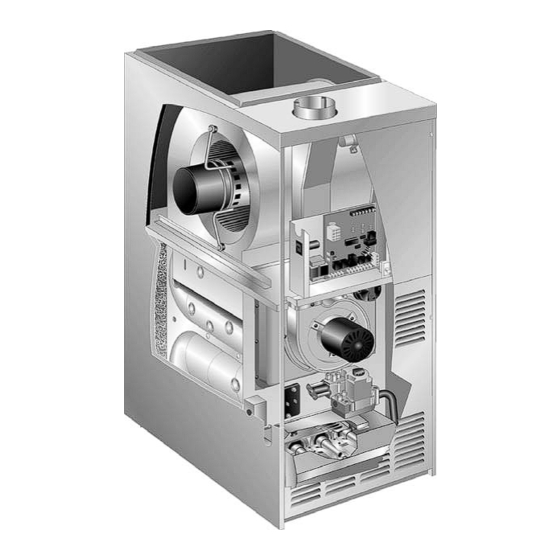
- Page 7 G60DFV(X) PARTS ARRANGEMENT Variable Speed Blower Motor Blower Assembly Secondary Limit (not shown) Internal Flue Pipe Assembly Gasket Circuit Power Choke Breaker (1HP Only) Flue Door Chase Interlock Switch Transformer Gasket Limit SureLightt Two−Stage Shield Variable Spee Integrated Control Board...
- Page 8 Board 18M99 gas valve or blower deck, before performing any service procedure. G60DFV units are equipped with the Lennox two−stage, variable speed integrated SureLight control board. The 1. Control Transformer (T1) system consists of a ignition / blower control board (figure...
- Page 9 After the 15−second pre−purge period, the SureLight ignitor warms up for 20 seconds after which the gas valve opens for a 4−second trial for ignition. The ignitor energizes during the trial until flame is sensed. If ignition is not proved during TW0−STAGE, VARIABLE SPEED INTEGRATED the 4−second period, the control will try four more times with CONTROL BOARD...
- Page 10 TABLE 1 TABLE 3 Two Stage Ignition / Blower Control Terminals SureLight Board 5 Pin Terminal Designation 120VAC Neutral PIN # Function Ignitor LINE Line 120VAC Neutral XFMR Transformer 120VAC Neutral Combustion Air Inducer High Speed Electronic Air Cleaner 120VAC Neutral Combustion Air Inducer Low Speed CIRC Indoor Blower 120VAC Neutral...
-
Page 11: Status Codes
(2) second pauses. One blink equals roughly 100 CFM. DS7−ON indicaties the DS to R" jumper has not been cut. When the jumper is cut the system will be operating with LENNOX HARMONY IIt (See Harmony Installation Instructions) or YELLOW with the CCB1 Efficiency Plus control. - Page 12 Dip Switch Settings TABLE 8 Cooling Mode Blower Speeds Switches 1 and 2 − Blower Off Delay The blower−on delay of 45 seconds is not adjustable. The blower−off delay (time Speed Switch 5 Switch 6 that the blower operates after the heating demand has 1 −...
- Page 13 D Once demand is met, motor ramps down to off. 100% CFM 100% CFM COOLING DEMAND 7−1/2 MIN G60DFV units date coded prior to 2−2006 will delay 60 seconds 100% CFM 82%CFM COOLING DEMAND Ramping Option D Ramping Option D S−...
- Page 14 Harmony II zone control board, blower is operating. The green CFM LED indicates the the CCB1 EfficiencyPlus humidity control or Lennox Signa- blower motor speed. Count the number of blinks between tureStatt. Refer to table 21 for operation sequence in ap- the two−second pauses to determine the CFM.
- Page 15 NOTE − Board 100870 provides 95 volts regulated to Board 100870 the ignitor. Beggining with the G60DFV−7, units are equipped with the Lennox two−stage, variable speed integrated SureLight Two Stage Operation / Thermostat Selection Jumper control board. The system consists of a ignition / blower The control can be utilized in two modes: SINGLE−STAGE...
- Page 16 DIAGNOSTIC LEDs INDOOR BLOWER DIP HEATING SWITCHES H= 24V HUMIDIFIER OUTPUT SWITCHES L= LENNOX SYSTEM OPERATION MONITOR 1= FUTURE USE ON−BOARD JUMPERS DIP SWITCH FUNCTIONS HTG DIP SWITCH(ES) FUNCTION T’stat Heat Stages (single or two−stage) Second Stage ON Delay (single−stage t’stat)
- Page 17 TWO−STAGE, VARIABLE SPEED INTEGRATED CONTROL BOARD FIGURE 6 Page 17...
- Page 18 TABLE 15 FLASH CODE STATUS / ERROR DESCRIPTION (X + Y) FLASH CODE DESCRIPTIONS Pulse A 1/4 second flash followed by four seconds of off time. Heartbeat Constant 1/2 second bright and 1/2 second dim cycles. LED flashes X times at 2Hz, remains off for two seconds, flashes Y times at 2Hz, remains off for four X + Y seconds, then repeats.
- Page 19 Dip Switch Settings operation during the cooling mode. The table below pro- vides the cooling mode blower speeds that will result from Heating Operation DIP Switch Settings different switch settings. Refer to blower tables at the front Switch 1 −− Thermostat Selection −− This unit may be used of this manual for corresponding cfm values.
- Page 20 Refer to table 21 (CCB1) and table 23 (SignatureStat) determine the CFM. Each blink represents approximately for operation sequence in applications including G60DFV, 100 CFM. a thermostat which features humidity control and a single−...
- Page 21 TABLE 22 G60DFV, CCB1 and Two−Speed Outdoor Unit OPERATING MODE SYSTEM DEMAND SYSTEM RESPONSE System Thermostat *Relative Humidity ****Compressor Blower CFM Comments Condition Demand (EfficiencyPlus Lights) Speed (COOL) **42%/46%/49 % of HIGH Compressor demand and indoor No demand. Acceptable Normal operation...
- Page 22 With Heat Pump − Cut W914 (R to DS) & W951 (R to O) on SureLight board Dave Lennox SignatureStat to use for this application − 51M26 1 heat / 1 cool or 51M28 − 2 heat / 2 cool for heat pumps *Dehumidification blower speed is 65% of COOL speed for 36A &...
- Page 23 With Heat Pump − Cut W914 (R to DS) & W951 (R to O) on SureLight board Dave Lennox SignatureStat to use for this application − 51M27 2 heat / 2 cool or 51M28 − 2 heat / 2 cool for heat pumps *Normal operation first stage cooling blower speed is as follows for units built before 09−2002: 65% of COOL for 36A, 36B,...
- Page 24 All G60DFV blower motors use single phase power. An external run capacitor is not used. The motor uses per- manently lubricated ball-type bearings.
- Page 25 Power Choke (L13) minutes after turning off power to the unit before attempt- A choke coil is used on G60DFV 5 ton 1 hp units. The ing to change speed taps. choke is located on the blower housing and is used to block radio frequency interference.
- Page 26 MOTOR SPEED CONTROL WITH D.C. PULSE-WIDTH MODULATION Motor speed is determined by the size of the electrical pulse sent to the motor windings. The longer the pulse, the faster the motor. OUTPUT FROM CONTROLLER TO MOTOR WINDINGS WINDINGS TURNED OFF WINDINGS TURNED ON Ç...
-
Page 27: Flame Sensor
7. Ignitor NOTE − The G60DFV(X) furnace contains electronic components that are polarity sensitive. Make sure that The SureLight ignitor is made of durable silicon nitride. Ig- the furnace is wired correctly and is properly grounded. nitor longevity is enhanced by controlling voltage to the ig- nitor. - Page 28 1.875 units use a surface type limit factory set to open at 125°F. −110 2.156" G60DFV−3 units and later use an airstream type limit factory −135 2.600" set to open at 135°. The secondary limit cannot be adjusted. 10. Flame Rollout Switches (S47) Flame rollout switch is a high temperature limit located on 13.
- Page 29 Prove Switch (S18) S18 is a dual combustion air proving switch (first and second Set Point High Set Point Low G60DFV Unit Heat Heat stage) located on the combustion air inducer orifice bracket. The switch is connected to the combustion air inducer hous- −070...
- Page 30 II−PLACEMENT AND INSTALLATION HONEYWELL VR8205 Series Gas Valve Make sure unit is installed in accordance with installation MANIFOLD HIGH FIRE PRESSURE ADJUSTMENT instructions and applicable codes. SCREW (under cap) III−START-UP A−Preliminary and Seasonal Checks 1 − Inspect electrical wiring, both field and factory installed lOW FIRE for loose connections.
- Page 31 Use of a specialty Gas Leak Detector is strongly recommended. It is available through Lennox under part number 31B2001. See Corp. WARNING 8411−L10, for further details. Do not use matches, candles, flame or any other source of Do not exceed 600 in−lbs (50 ft−lbs) torque when...
- Page 32 TABLE 29 IMPORTANT All G60DFV Units Natural Line Pressure WC" 4.5 − 10.5 11.0 − 13.0 For safety, shut unit off and remove manometer as Manifold Pressure High soon as an accurate reading has been obtained. 10.0 Heat WC" Take care to replace pressure tap plug.
- Page 33 Current passes from the sensor through the flame to When the G60DFV is running in the heating mode, the ground to complete a safety circuit. indoor blower will run on the heating speed designated by the positions of dip switches 11 and 12.
- Page 34 C−External Static Pressure B−Filters All filters are installed external to the unit. Filters should be 1 − Tap locations shown in figure 21. inspected monthly. Clean or replace the filters when neces- STATIC PRESSURE TEST 2 − Punch a 1/4" diameter hole sary to ensure that the furnace operates properly.
- Page 35 11 −NO units only − Remove the three screws that attach G60DFV(X) Internal Flue Pipe and Chase the NO insert to the corbel at the entrance to each Unit Top Cap heat exchanger section. Carefully remove the NO sert from each section. See figure 24.
- Page 36 16 −Attach the exhaust end (positive pressure) of the vacu- WARNING um cleaner to the top of the heat exchanger section. Any loose debris will be forced to the bottom of the heat The blower access panel and vent pipe must be se- exchanger section.
- Page 37 VII− Wiring and Sequence of Operation A−G60DFV with SureLight Board 18M99 Page 37...
- Page 38 B−Sequence of Operation. Single−Stage Thermostat, Two Stage Heat. Jumper E20 set at SINGLE" Sequence depends on type thermostat used. Units are 1− SureLight control energizes combustion air inducer B6 applicable for single stage or two stage thermostats. on low heat speed. Combustion air inducer runs until Both type thermostats are described below.
- Page 39 C−Flow Chart SureLight Board 18M99 HEATING SEQUENCE OF OPERATION NORMAL AND ABNORMAL HEATING MODE GAS VALVE OFF. COMBUSTION AIR INDUCER POWER ON OFF. INDOOR BLOWER OFF. CHECK FOR BROKEN IGNITOR OR OPEN IGNITER CIRCUIT. DS 1 AND DS 2 ALTERNATING FAST FLASH. CONTROL SELF−CHECK OKAY? GAS VALVE OFF.
- Page 40 HEATING SEQUENCE OF OPERATION CONTINUED THERMOSTAT CALLS FOR HEAT DS1 AND DS2 SIMULTANEOUS FAST FLASH (Refer to box A on previous page) FIRST−STAGE (LOW FIRE) PROVE GAS VALVE OFF. COMBUSTION AIR INDUCER SWITCH CLOSED WITHIN 2.5 MINUTES? OFF. INDOOR BLOWER OFF. UNIT WILL RETRY AFTER 5−MINUTE WAIT PERIOD.
- Page 41 HEATING SEQUENCE OF OPERATION CONTINUED THERMOSTAT CALLS FOR HEAT. DS1 AND DS2 SIMULTANEOUS FAST FLASH. SEE BOX A. FLAME SIGNAL ABOVE (u0.23 microamps) LOW FLAME SIGNAL (Does not affect control operation) DS1 SLOW FLASH, DS2 FAST FLASH. SINGLE−STAGE THERMOSTAT MODE TWO STAGE THERMOSTAT MODE (E20 SET AT SINGLE") (E20 SET AT TWO")
- Page 42 HEATING SEQUENCE OF OPERATION CONTINUED SEE BOX A NORMAL OPERATION DS1 AND DS2 SIMULTANEOUS SLOW FLASH. SEE BOX B THERMOSTAT CALLS FOR HEAT DS 1 AND DS 2 SIMULTANEOUS FAST FLASH GAS VALVE OFF. COMBUSTION AIR INDUCER OFF. INDOOR BLOWER ON. IS PRIMARY AND SECONDARY LIMIT DS1 SLOW FLASH, DS2 ON, AND ROLLOUT SWITCH CLOSED?
- Page 43 COOLING SEQUENCE OF OPERATION POWER ON IS POLARITY REVERSED? SIGNAL POLARITY REVERSED. DS1 FAST FLASH, DS2 SLOW FLASH. SIGNAL IMPROPER GROUND AT DS. LOW VOLTAGE SIGNAL AT DS HOLDS IS THERE IS VOLTAGE SIGNAL HOLDS UNTIL VOLTAGE RISES ABOVE 75 VOLTS. PROPER GROUND? ABOVE 75 VOLTS? UNTIL UNIT IS...
- Page 44 D−G60DFV with SureLight Board 100870 Page 44...
- Page 45 E−Sequence of Operation Single−Stage Thermostat, Two Stage Heat. Dip Switch set at SINGLE" Sequence depends on type thermostat used. G60DFV 1− SureLight control energizes combustion air inducer B6 units are applicable for single stage or two stage ther- on low heat speed. Combustion air inducer runs until mostats.
- Page 46 F−Flow Chart SureLight Board 100870 HEATING SEQUENCE OF OPERATION NORMAL AND ABNORMAL HEATING MODE POWER ON GAS VALVE OFF. COMBUSTION AIR INDUCER OFF. INDOOR BLOWER OFF. (RESET CONTROL BY CONTROL SELF−CHECK OKAY? TURNING MAIN POWER OFF.) POLARITY REVERSED. POLARITY OKAY? STATUS ERROR CODE 5 + 4.
- Page 47 HEATING SEQUENCE OF OPERATION CONTINUED THERMOSTAT CALLS FOR HEAT STATUS LED − HEARTBEAT (Refer to box A on previous page) FIRST−STAGE (LOW FIRE) PRESSURE GAS VALVE OFF. COMBUSTION AIR INDUCER SWITCH CLOSED WITHIN 2.5 MINUTES? OFF. INDOOR BLOWER OFF. UNIT WILL RETRY AFTER 5−MINUTE WAIT PERIOD.
- Page 48 HEATING SEQUENCE OF OPERATION CONTINUED THERMOSTAT CALLS FOR HEAT. STATUS LED −− HEARTBEAT. SEE BOX A. FLAME SIGNAL ABOVE (u1.40 microamps) LOW FLAME SIGNAL (Does not affect control operation) STATUS ERROR CODE 1 + 2. SINGLE−STAGE THERMOSTAT MODE TWO STAGE THERMOSTAT MODE (DIP SWITCH SET AT SINGLE") (DIP SWITCH SET AT TWO") START SECOND−STAGE RECOGNITION...
- Page 49 HEATING SEQUENCE OF OPERATION CONTINUED SEE BOX A NORMAL OPERATION. SEE BOX B THERMOSTAT CALLS FOR HEAT. RETURN TO FIRST−STAGE HEAT MODE. FIRST−STAGE CONTINUES UNTIL SECOND− STAGE PRESSURE SWITCH CAN BE PROVEN SECOND−STAGE (HIGH FIRE) HEAT or HEAT DEMAND IS SATISFIED. A FIVE (5) PRESSURE SWITCH CLOSED? MINUTE WAIT PERIOD IS INITIATED BEFORE RETRY.
- Page 50 COOLING SEQUENCE OF OPERATION POWER ON SIGNAL POLARITY REVERSED. CONTROL WILL CONTINUE TO CALL FOR COOLING IS POLARITY REVERSED? IN THIS CONDITION. STATUS ERROR CODE 5 + 4. SIGNAL IMPROPER GROUND AT LED. CONTROL WILL CONTINUE TO CALL FOR COOLING IS THERE IN THIS CONDITION.
- Page 51 CONTINUOUS LOW SPEED FAN SEQUENCE OF OPERATION MANUAL FAN SELECTION MADE AT THERMOSTAT. AFTER 2 SECOND DELAY, INDOOR BLOWER IS ENERGIZED ON CONTINUOUS FAN SPEED. THERMOSTAT CALLS FOR FIRST STAGE COOL. THERMOSTAT CALLS FOR FIRST−STAGE HEAT. INDOOR BLOWER RAMPS TO FIRST STAGE AFTER 45−SECOND DELAY, INDOOR BLOWER COOLING SPEED AFTER A 2−SECOND DELAY.
- Page 52 VIII− Field Wiring & Jumper Settings A−SureLight Board 18M99 TABLE 33 Field Wiring Applications Jumper Settings (See figure 4) Thermostat Thermostat Wiring Connections Wiring Connections W915 W914 W951 1 Heat / 1 Cool SINGLE Intact Intact Intact CONTROL OUTDOOR T’STAT TERM.
- Page 53 TABLE 33 Field Wiring Applications (Continued) Jumper Settings (See figure 4) Thermostat Thermostat Wiring Connections Wiring Connections W915 W914 W951 1 Heat / 2 Cool SINGLE Intact CONTROL OUTDOOR CCB1 with CCB1 T’STAT TERM. STRIP UNIT NOTE − Use dip switch 3 to set second−stage HSXA19 heat ON delay.
- Page 54 TABLE 33 Field Wiring Applications (Continued) Jumper Settings (See figure 4) Thermostat Thermostat Wiring Connections Wiring Connections W915 W914 W951 2 Heat / 1 Cool Intact Intact Intact CONTROL OUTDOOR T’STAT TERM. STRIP UNIT HSXB15 (LSOM) FM21 Heat Pump / 1 SINGLE Intact Intact...
- Page 55 B−SureLight Board 100870 Jumper Settings (See figure 5) W915 W914 Dehu- Two−Stage midification W951 Thermostat Wiring Connections DIP Switch 1 Cooling or Harmony Heat Pumps 1Heat / 1 Cool Intact Intact Intact CONTROL OUTDOOR T’STAT TERM. STRIP UNIT NOTE − Use DIP switch 2 to set second−stage heat ON delay.
- Page 56 Jumper Settings (See figure 5) W915 W914 Dehu- Two−Stage midification W951 Thermostat Wiring Connections DIP Switch 1 Heat Pumps Cooling or Harmony 2 Heat / 2 Cool Intact Intact CONTROL OUTDOOR T’STAT TERM. STRIP UNIT 2 Heat / 2 Cool Intact CONTROL OUTDOOR...
- Page 57 IX− Troubleshooting SureLight Board 18M99 UPON INITIAL POWER UP, REMOVE ALL THERMOSTAT DEMANDS TO THE UNIT PROBLEM: 1 UNIT FAILS TO OPERATE IN THE COOLING, HEATING, OR CONTINUOUS FAN MODE Condition Possible Cause Corrective Action / Comments 1.1.1 ACTION 1 − Check 120V main voltage. −...
- Page 58 PROBLEM 2: UNIT FAILS TO FIRE IN THE HEATING MODE, COMBUSTION AIR INDUCER DOES NOT ENERGIZE Condition Possible Cause Corrective Action / Comments ACTION 1 − Check continuity across switch(es). Switches reset automatically upon cool down. − Unit operates with a cooling or contin- 2.1.1 Rollout switch must be reset manually.
- Page 59 PROBLEM 3: UNIT FAILS TO FIRE IN THE HEATING MODE, COMBUSTION AIR BLOWER ENERGIZES, IGNITOR IS NOT ENERGIZED. Condition Possible Cause Corrective Action/Comments 3.1.1 ACTION 1 − Check that the pressure switch line − Unit operates with a cooling and Pressure switch does not close due is correctly routed.
- Page 60 PROBLEM 4: UNIT FAILS TO FIRE IN THE HEATING MODE, COMBUSTION AIR BLOWER ENERGIZES, IGNITOR IS ENERGIZED. Condition Possible Cause Corrective Action/Comments ACTION 1 − Check line pressure at the gas valve. 4.1.1 Pressure should not exceed 13" WC for both nat- −...
- Page 61 PROBLEM 5: BURNERS LIGHT WITH HEATING DEMAND BUT UNIT SHUTS DOWN PREMATURELY (CONT.) Condition Possible Cause Corrective Action/Comments ACTION 1 − Check that the manifold pressure matches value listed on nameplate. See installa- − Combustion air inducer energizes 5.3.1 tion instructions for proper procedure. with a heating demand.
- Page 62 PROBLEM 5: BURNERS LIGHT WITH HEATING DEMAND BUT UNIT SHUTS DOWN PREMATURELY (CONT.) ACTION 1 − Check that the sensor is properly lo- 5.5.1 cated. − Combustion air inducer energizes ACTION 2 − Check that the sense wire is properly Loose sensor wire connection causes with a heating demand.
- Page 63 Two Stage Variable Speed Control Board 100870 UPON INITIAL POWER UP, REMOVE ALL THERMOSTAT DEMANDS TO THE UNIT PROBLEM: 1 UNIT FAILS TO OPERATE IN THE COOLING, HEATING, OR CONTINUOUS FAN MODE Flash Code Possible Cause Corrective Action / Comments LED X + Y 1.1.1 ACTION 1 −...
- Page 64 PROBLEM 2: UNIT FAILS TO FIRE IN THE HEATING MODE, COMBUSTION AIR BLOWER DOES NOT ENERGIZE Flash Code Corrective Action / Comments Possible Cause LED X + Y ACTION 1 − Check continuity across switch(es). 2.1.1 Switches reset automatically upon cool down. Unit operates with a cooling or ACTION 2 −...
- Page 65 PROBLEM 4: UNIT FAILS TO FIRE IN THE HEATING MODE, COMBUSTION AIR INDUCER ENERGIZES, IGNITOR IS NOT ENERGIZED. Flash Code Possible Cause Corrective Action/Comments LED X + Y 4.1.1 ACTION 1 − Check for restricted vent. Remove all blockage. − Unit operates with a cooling and Prove switch does not close due to ACTION 2: Check for proper vent sizing.
- Page 66 PROBLEM 5: UNIT FIRES ON LOW FIRE, FAILS TO GO TO HIGH FIRE OPERATION Flash Code Possible Cause Corrective Action/Comments LED X + Y 5.1.1 ACTION 1 − Check for restricted vent. Remove all blockage. − Unit light s normally during low fire Prove switch does not close due to ACTION 2: Check for proper vent sizing.
- Page 67 PROBLEM 6: UNIT FAILS TO FIRE IN THE HEATING MODE, COMBUSTION AIR BLOWER ENERGIZES, IGNITOR IS ENERGIZED. Flash Code Possible Cause Corrective Action/Comments LED X + Y ACTION 1 − Check line pressure at the gas valve. 6.1.1 Pressure should not exceed 13" WC for both nat- Unit operates with a cooling and ural and propane.
- Page 68 PROBLEM 7: BURNERS LIGHT WITH HEATING DEMAND BUT UNIT SHUTS DOWN PREMATURELY (CONT.) Flash Code Possible Cause Corrective Action/Comments LED X + Y ACTION 1 − Check that the manifold pressure matches value listed on nameplate. See installa- Combustion air inducer energizes 7.3.1 tion instructions for proper procedure.
- Page 69 PROBLEM 7: BURNERS LIGHT WITH HEATING DEMAND BUT UNIT SHUTS DOWN PREMATURELY (CONT.) Flash Code Possible Cause Corrective Action/Comments LED X + Y ACTION 1 − Check that the sensor is properly lo- Combustion air inducer energizes 7.5.1 cated. with a heating demand. ACTION 2 −...
- Page 70 ICM−2 WITH TWO STAGE VARIABLE SPEED CONTROL BOARD 120V to the motor must not be interrupted. All connections for check out will be from the volt- age source below (battery or 24V) to plug J46, after disconnecting from blower control board. REMOVE PLUG FROM BOARD CHECK−OUT PROCEDURE USING BATTERY CHECK−OUT PROCEDURE USING 24V SOURCE...