
Related Manuals for Midea MPM1-10CEN1-BB6


Summary of Contents for Midea MPM1-10CEN1-BB6
- Page 1 Portable air conditioner MPM1-10CEN1-BB6 MPM1-10EEN1-BB6 MPM1-10CRN1-BB6 MPM1-10ERN1-BB6...
-
Page 2: Table Of Contents
Content CONTENT Safety precaution ........................1 1.1 Installation ............................1 1.2 Caution ............................... 1 1.3 Operational ............................1 Specification .......................... 3 Out dimension ........................5 Display ............................ 6 ... -
Page 3: Safety Precaution
Safety Precaution Safety precaution Installation For electrical work, contact the dealer, seller, a qualified electrician, or an Authorized service center. Do not disassemble or repair the product by yourself. Sharp edges could cause injury, be especially careful of the case edges and the fins on the condenser and evaporator. - Page 4 Safety Precaution Replace the all batteries in the remote control with new ones of the same type. Do not mix old and mew batteries or different types of batteries. Do not recharge or disassemble the batteries. Do not dispose of batteries in a fire. If the liquid from the batteries gets onto your skin or clothes, wash it well with clean water.
-
Page 5: Specification
Outer dimension Specification MPM1-10CEN1-BB6 MPM1-10EEN1-BB6 Model MPM1-10CRN1-BB6 MPM1-10ERN1-BB6 Nameplate marking Power supply Ph-V-Hz 1φ,115V~,60Hz 1φ,115V~,60Hz Cooling Capacity1 Btu/h 10000 10000 Cooling Power consumption1 1133 1133 Cooling Rated current1 10.0 10.0 Cooling EER2 Btu/W·h Electrical heater ------ 1465 System data Refrigerant type... - Page 6 Outer dimension a. Number of rows b. Tube pitch(a)x row pitch(b) 21X13.37 21X13.37 c. Fin spacing d. Fin type (code) Hydrophilic aluminum Hydrophilic aluminum Ф7×0.25×0.18, Ф7×0.25×0.18, etude outside diamante type inner groove tube inner groove tube facial length x height x width 372x294x26.74 372x294x26.74 g.
-
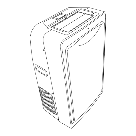
Page 7: Out Dimension
Outer dimension Out dimension... -
Page 8: Display
External view, part, display isplay LED display LCD display... -
Page 9: Refrigerant Cycle Diagram
Refrigerant cycle diagram Refrigerant cycle diagram The figure below is a brief description of the important components and their function in what is called the refrigeration system... -
Page 10: Pcb Drawing & Wiring Diagram
Installation detail PCB drawing & wiring diagram 10K Model The below picture is fit for: MPM1-10CEN1-BB6, MPM1-10CRN1-BB6, MPM1-10EEN1-BB6, MPM1-10ERN1-BB6... -
Page 11: Position Requirement For Installation
Installation detail Position requirement for installation Installation must be in a flat and spacious location where the air outlets will not be covered up. A minimum clearance of 30cm from a wall or other obstacles should be kept. The appliance shall not be used in the washroom. -
Page 12: Installation In A Double-Hung Sash Windows
Installation detail Installation in a double-hung sash windows 6.4.1 Cut the foam seal (adhesive type) to the proper length and attach it to the window stool. 6.4.2 Attach the window panel to the window stool. Adjust the length of the window panel according to the width of window, short the adjustable panel if the width of window is less than 26”. -
Page 13: Installation In A Sliding Sash Windows
Installation detail Installation in a sliding sash windows 6.5.1 Cut the foam seal to a proper length and adhesive to the window frame. 6.5.2 Attach the window panel to the window stool. Adjust the length of the sliding window panel according to the width of window, short the adjustable panel if the width of window is less than 26”. -
Page 14: Permanent Installation
Installation detail 6.5.4 Close the sliding sash securely against the window. 6.5.5 Cut the foam seal to an appropriate length and sealing the open gap between the top window sash and outer window sash. Show as below picture. Permanent installation 6.6.1 Attach one end of the duct to the exhaust air outlet of the mobile air conditioner. - Page 15 Installation detail 6.6.4 Cover the hole using the adaptor cap when not in use.
-
Page 16: Feature
Feature Feature LED display (LCD optional) air out grille Flat plane design Sliver spray 8 meters remote controller Turbo cooling function Flexible air exhaust Advanced shower system 24 hour on/off Cooling Fan only No water tank design... -
Page 17: Electronic Function
Electronic function Electronic function Terms and definitions TA: Temperature of ambient, (T1). TC: Temperature of condenser, (T3). TE: Temperature of evaporator, (T2). TS: Setting temperature by remoter controller or control plane. WL1: water level1. WL2: water level2. WL3: water level3. WL4: water level4. -
Page 18: Protection Function
Electronic function Protection function 8.4.1 Time delay safety control (3 minutes). When the compressor is stopped by the remote controller, it restarts after 3 minutes when the remote controller is turn ON. When the setting temperature is reached during cooling operation, the compressor stop and it will not start for 3 minutes. - Page 19 Electronic function 8.4.4 Water full protection. There are four switches on the base-pan water tank. S1, S2, S3, S4. As you see the below graph. If the water level exceed WL1, S1 activity, the Pump 1 that in charge of shower system start to work.
-
Page 20: Cooling Operation
Electronic function 8.4.5 Malfunction LCD or LED display Malfunction Water full protection. Drainage protection. T3 sensor malfunction. T2 sensor malfunction. T1 sensor malfunction. Cooling operation 8.5.1 At cooling mode, the range of work is 17’C~30’C (62’F ~88’F). 8.5.2 The fan setting: AUTO, low, middle, high, turbo. 8.5.3 The action of compressor at cooling mode: The inner fan motor will start when the unit into cooling mode, the outer fan motor work status... -
Page 21: Auto Mode
Electronic function If the inner fan is at middle wind and TA-TS≥-1'C, the fan motor turn to low fan and continue running 1 minute at lease. 8.5.7 The ionizer and timer are available at cooling mode. Auto mode 8.6.1 At auto mode, the range of work is 17’C~30’C (62’F ~88’F). 8.6.2 At auto mode, the inner fan speed is only judge by the TA and TS, people can’t set it. -
Page 22: Heating Mode
Electronic function Heating mode 8.9.1 8.9.2 At heating mode, the setting temperature range is 17’C~30’C. (62’F~88’F) 8.9.3 At heating mode, the action of the electric heater: 8.9.4 The inner fan speed can by select at heating mode----Auto, low, middle, and high. The outer fan is off and compressor is off at heating mode. -
Page 23: Basic Test Procedure
Basic test procedure Basic test procedure Defective compressor Compressors are single phase, 115 or 230/208 volt, depending on the model unit. All compressor motors are permanent split capacitor type using only a running capacitor across the start and run terminal. All compressors are internally spring mounted and externally mounted on rubber isolators. -
Page 24: Sealed Refrigeration System Repairs
Basic test procedure If test shows: A. Below normal high side pressure. B. Above normal low side pressure. C. Low temperature difference across coil. The compressor valves are faulty - replace the compressor. 9.1.4 Terminal overload (external) Some compressors are equipped with an external overload which is located in the compressor terminal box adjacent to the compressor body the overload is wired in series with the common motor terminal. - Page 25 Basic test procedure Acetylene Welder Electronic Halogen Leak Detector (G.E. Type H-6 or equivalent.) Accurate refrigerant charge measuring device such as: a. Balance Scales - 1/2 oz. accuracy b. Charging Board - 1/2 oz. accuracy High Pressure Gauge - (0 - 400 lbs.) Low Pressure Gauge - (30 - 150 lbs.) Vacuum Gauge - (0 - 1000 microns) 9.2.2...
-
Page 26: Fan Motor
Basic test procedure Restart unit several times after allowing pressures to stabilize. Pinch off process tubes, cut and solder the ends. Remove pinch off tool, and leak check the process tube ends. 9.2.4 Special procedure in the case of compressor motor burnout. Recover all refrigerant and oil from the system. -
Page 27: Capacitor
Basic test procedure Apply "live" test cord probes on each of the remaining wires from the speed switch or system switch to test intermediate speeds. Capacitor A run capacitor is wired across the auxiliary and main winding of a single phase permanent split capacitor motor such as the compressor and fan motor. -
Page 28: Characteristic Of Temperature Sensor
Characteristic of temperature sensor Characteristic of temperature sensor Resistance Resistance Resistance Temp.℃ Temp.℃ Temp.℃ KΩ KΩ KΩ 62.2756 14.6181 4.3874 58.7079 13.918 4.2126 56.3694 13.2631 4.0459 52.2438 12.6431 3.8867 49.3161 12.0561 3.7348 46.5725 11.5 3.5896 10.9731 3.451 41.5878 10.4736 3.3185 39.8239 3.1918 37.1988... -
Page 29: Trouble Shooting
Trouble shooting Trouble shooting PROBLEM POSSIBLE CAUSE REMEDY Check the power supplier if the power supplier is supplied Power failure to the unit. Check the power cord and correct if damaged. No power display Transformer (Discharge Check resistance between the two input/output lines on on panel or any transformer before transformer. - Page 30 Trouble shooting Loose screws Tighten them. Replace the motor if knocking sounds continue when Worn bearings running or loose, or the motor hums or noise appears to be internal while running. Voltage Check voltage. Call Supply Authority if not within limits. Check the wire connections, if loose, repair or replace the terminal.
- Page 31 Trouble shooting Regulate the flow if capillary tube and make the Capillary tube evaporating temperature appropriate if the evaporator is frosted. Replace if blocked. Repair joint if leaking. The inlet and outlet valve of the compressor is damaged, making the low pressure connected with the high pressure. Compressor The refrigerating system can not produce high pressure and low pressure.
-
Page 32: Exploded View & Spare-Part
Exploded view & spare-part Exploded view & spare-part 12.1 Exploded view of unit... -
Page 33: Exploded View Of Accessory Part
Exploded view & spare-part 12.2 Exploded view of accessory part... -
Page 34: Spare Part List
Exploded view & spare-part 12.3 Spare part list Model name UL-KC30Y1-M1(B6)(MPM1-10CR-BB6) Compressor EH135X1CY-1DZDU2(Toshiba) Fan motor (inner) YDK62-4AS Fan motor (outer) YDK65-4AS Name Quantity Factory code E. part installation plane assembly 2332549085 Installation plane assembly 2122549014 Comp. capacitor 2240109021 Holder of capacitor 2120010010 Chassis assembly 2112549128... - Page 35 Exploded view & spare-part Drainage tube 2112549129 E. part aseembly 2332539006 21.1 E. part box 2112549075 21.2 Main PCB assembly 2132549020 21.3 Cpacitor 2240110105 21.4 Transformer 2230090122 21.5 Main connect PCB 2132549019 Cpacitor 2240110104 Room sensor 2230130110 Evap. Sensor 2242049075 Cond.