Table of Contents
Advertisement
Service Manual
N series
N portable (AHAM
standard)
N portable (ASHRAE
standard)
N1 portable (AHAM
standard)
N1 portable (ARI
standard)
Website: www.mideaaircon.com
AIR CONDITIONER
Portable Type
MPN-05CRN1-BH2(H)
MPN-08CRN1-BH2(H)
MPN-12CRN1-BH9(H)
MPN-05CRN1-BH9
MPN-08CRN1-BH9
MPN-085CRN1-BH9
MPN-10CRN1-BH9
MPN-12CRN1-BH9
MPN-14CRN1-BI6
MPN1-08CRN1-BH2(H)
MPN1-09CRN1-BH2(H)
MPN1-10CRN1-BH2(H)
MPN1-12CRN1-BH9(H)
MPN1-08CRN1-BH9
MPN1-10CRN1-BH9
MPN1-12CRN1-BH9
MPN1-14CRN1-BI6
US-KC15Y1/N1-N(H2H)
US-KC23Y1/N1-N(H2H)
US-KC35Y1/N1-N(H9H)
US-KC15Y1/N1-N(H9)
US-KC23Y1/N1-N(H9)
US-KC25Y1/N1-N(H9)
US-KC30Y1/N1-N(H9)
US-KC35Y1/N1-N(H9)
US-KC41Y1/N1-N(I6)
US-KC23Y1/N1-N1(H2H)
US-KC26Y1/N1-N1(H2H)
US-KC30Y1/N1-N1(H2H)
US-KC35Y1/N1-N1(H9H)
US-KC23Y1/N1-N1(H9)
US-KC30Y1/N1-N1(H9)
US-KC35Y1/N1-N1(H9)
US-KC41Y1/N1-N1(I6)
N1 series
Advertisement
Table of Contents

Related Manuals for Midea N series


Summary of Contents for Midea N series
- Page 1 Website: www.mideaaircon.com Service Manual AIR CONDITIONER Portable Type N series N1 series MPN-05CRN1-BH2(H) US-KC15Y1/N1-N(H2H) N portable (AHAM MPN-08CRN1-BH2(H) US-KC23Y1/N1-N(H2H) standard) MPN-12CRN1-BH9(H) US-KC35Y1/N1-N(H9H) MPN-05CRN1-BH9 US-KC15Y1/N1-N(H9) MPN-08CRN1-BH9 US-KC23Y1/N1-N(H9) MPN-085CRN1-BH9 US-KC25Y1/N1-N(H9) N portable (ASHRAE standard) MPN-10CRN1-BH9 US-KC30Y1/N1-N(H9) MPN-12CRN1-BH9 US-KC35Y1/N1-N(H9) MPN-14CRN1-BI6 US-KC41Y1/N1-N(I6) MPN1-08CRN1-BH2(H) US-KC23Y1/N1-N1(H2H)
-
Page 2: Table Of Contents
CONTENT Safety precaution ....................1 Installation ............................ 1 Caution ............................1 Operational ............................ 1 Out dimension ......................2 Display ........................3 Refrigerant cycle diagram ..................4 PCB drawing & wiring diagram ................. 5 Specification ......................6 Installation detail....................7 Position requirement for installation ....................7 Preparation work.......................... -
Page 3: Safety Precaution
Safety precaution Installation For electrical work, contact the dealer, seller, a qualified electrician, or an Authorized service center. Do not disassemble or repair the product by yourself. Sharp edges could cause injury, be especially careful of the case edges and the fins on the condenser and evaporator. -
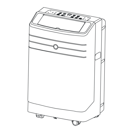
Page 4: Out Dimension
Out dimension... -
Page 5: Display
Display Rem ote signal rec eptor (The model has no (Some m ode ls ha ve t he auto swing feature sig nal receptor on th e fro nt panel , Fi g.2) wit hou t t his butt on) Fig.4 ) and DOWN( ) button... -
Page 6: Refrigerant Cycle Diagram
Refrigerant cycle diagram The figure below is a brief description of the important components and their function in what is called the refrigeration system... -
Page 7: Pcb Drawing & Wiring Diagram
PCB drawing & wiring diagram T hi s s ym bo l in di ca te s th e e le me nt i s o pt io na l, th e a ct ua l sh ap e sh al l p re va il... -
Page 8: Specification
Specification Model System Design Amps Watts Cooling Amount Air Flow (Cool) (Cool) Market model Compressor Pressure Btu/H Btu/H.W oz/g Psig /H(CFM) MPN-05CRN1-BH2(H) 5000 39A121AA&54KA R410A 10.2/290 550/340 360/310/270 MPN-08CRN1-BH2(H) 8000 39A191AD&5JKB R410A 11.3/320 550/340 360/310/270 MPN-12CRN1-BH9(H) 12000 11.9 1340 44A281BG&FJKC R410A 15.2/430 550/340... -
Page 9: Installation Detail
Installation detail Position requirement for installation Installation must be in a flat and spacious location where the air outlets will not be covered up. A minimum clearance of 30cm from a wall or other obstacles should be kept. The appliance shall not be used in the washroom. -
Page 10: Installation In A Double-Hung Sash Windows
Installation in a double-hung sash windows 7.3.1 Cut the foam seal (adhesive type) to the proper length and attach it to the window stool. 7.3.2 Attach the window panel to the window stool. Adjust the length of the window panel according to the width of window, short the adjustable panel if the width of window is less than 26”. -
Page 11: Installation In A Sliding Sash Windows
7.3.4 Close the window sash securely against the window. 7.3.5 Cut the foam seal to an appropriate length and sealing the open gap between the top window sash and outer window sash. Show as below picture. Installation in a sliding sash windows 7.4.1 Cut the foam seal to a proper length and adhesive to the window frame. - Page 12 7.4.3 Cut the foam seal (adhesive type) to the proper length attach it on the top of window. Show as below picture. 7.4.4 Close the sliding sash securely against the window. 7.4.5 Cut the foam seal to an appropriate length and sealing the open gap between the top window sash and outer window sash.
-
Page 13: Feature
Feature single louver flat appearance,Simple and generous Straight condenser , low cost、 High efficiency duct inside(After the lower right panel ) High heat exchanger designed Turbo cooling function Flexible air exhaust Advanced shower system Follow me function 24 hour on/off Cooling Fan only No water tank design... -
Page 14: Basic Test Procedure
Double louver flat appearance,Simple and generous Straight condenser , low cost、 High-efficiency duct inside(After the lower right panel ) High heat exchanger designed Turbo cooling function Flexible air exhaust Advanced shower system Follow me function 24 hour on/off Cooling Fan only No water tank design Basic test procedure Defective compressor... - Page 15 contact as a good connection is a must) and the other probe in turn to each compressor terminal (see Figure 2.) If a reading is obtained, the compressor is grounded and must be replaced. 9.1.3 Checking the compressor efficiency The reason for compressor inefficiency is normally due to broken or damaged suction and/or discharge valves, reducing the ability of the compressor to pump refrigerant gas.
-
Page 16: Sealed Refrigeration System Repairs
compressor overload is open and the compressor must be replaced. Sealed refrigeration system repairs 9.2.1 Equipment require 1. Voltmeter 2. Ammeter 3. Ohmmeter 4. E.P.A. Approved Refrigerant Recovery System. 5. Vacuum Pump (capable of 200 microns or less vacuum.) 6. Acetylene Welder 7. -
Page 17: Fan Motor
NOTE: If the entire charge will not enter the high side, allow the remainder to enter the low side in small increments while operating the unit. 12. Restart unit several times after allowing pressures to stabilize. Pinch off process tubes, cut and solder the ends. -
Page 18: Characteristic Of Temperature Sensor
capacitor motor such as the compressor and fan motor. A single capacitor can be used for each motor or a dual rated capacitor can be used for both. The capacitor's primary function is to reduce the line current while greatly improving the torque characteristics Resistance Resistance... -
Page 19: Trouble Shooting
Trouble shooting PROBLEM POSSIBLE CAUSE REMEDY Check the power supplier if the power supplier is supplied to Power failure the unit. Check the power cord and correct if damaged. No power display Check resistance between the two input/output lines on on panel or any Transformer (Discharge transformer. - Page 20 intermittently Test capacitor. Replace if not within +/-10% of manufacture's rating. Check bearings. Replace the motor if the blower wheel cannot rotate freely. Pay attention to any change from high speed to low speed. Replace the motor if the speed does not change. The amount of the refrigerant is too much, making the Refrigerant compressor load too big.
- Page 21 Determine if the unit is properly sized for the area to be cooled Unit undersized or heated. Condenser and Evaporator Clean or replace if restricted. shaded pole motor failure Check and replace if the motor is failure. Check the fan capacitor and replace if not within +/-10% of Fan motor manufactures rating.
- Page 22 Part Name BOM code Front panel 201125190041 assembly Window for receiving remote 201125190043 controller signal Receiving board 201325290014 assembly Front panel 201125190044 Cover of Air-out frame 201125190039 assembly Panel(Mid) 201125190042 Display box 2033252A0019 assembly display board 201325490127 assembly E-part box 201225590019 cover E-Part box...
- Page 23 Base of control 201225590020 Capacitor 202401100019 Capacitor 202401100122 Transformer 202300900193 Inside fan scroll 201125190148 assembly Bottom holder 5.11 1 of indoor 201125190055 Volute Shell Net cover for 5.12 201225190010 Air out frame Cover of 5.13 indoor Volute 201125190054 Shell Cross flow fan 5.14 201100200113 assembly...
- Page 24 Fixing joint for 201125490271 water drain Air discharger 201125690024 Outdoor wind discharging 201125190159 pipe Air Outlet 201125190130 Tie-in Window 201125090001 sealing board I Window sealing board 201125090002 Evaporator 201525390078 Remote 2033550A3695 contrller Compressor 201402000490 Condenser 201525390089 Exploded View & Parts Listing: MPN1-08CRN1-BH9 Part Name BOM code Front panel assembly...
- Page 25 Receiving board 201325290014 assembly Front panel 201125190044 Cover of Air-out 201125190039 frame assembly Panel(Mid) 201125190042 Display box assembly 2033252A0019 display board 2013254A0011 assembly control panel 201125190157 E-part box cover 201225590019 E-Part box assembly 203325190028 Capacitor clamp 201225590021 Compressor capacitor 202401090005 Main control board 201325190032 Installation board for...
- Page 26 Outdoor centrifugal 201100100702 Outdoor volute shell 201125190051 cover Fan motor 202400400969 Rear panel assembly 201125190062 Drain stopper 202725490002 Fixing joint for water 201125490271 drain Air discharger 201125690024 Outdoor wind 201125190159 discharging pipe Air Outlet Tie-in 201125190130 Window sealing 201125090001 board I Window sealing 201125090002 board II...
- Page 27 Window for receiving remote 201125590042 controller signal E-Part box 203325390081 assembly Installation board for Main 201125190038 control board Main control 201325190034 board Transformer 202300900193 Capacitor clamp 201225590021 Base of control 201225590020 Compressor 202401000810 capacitor Capacitor,Fan 202401100122 Motor Capacitor,Fan 202401100019 Motor Chassis 2011251A0112 assembly...
- Page 28 6.18 Louver motor 202400200039 Cross flow fan 6.19 201100200114 assembly 6.20 Fan motor 202400400978 indoor frame 201125290031 assembly Rear panel 201125290032 assembly Fixing joint for 201125490271 water drain Drain stopper 202725490002 Drain stopper 202725490013 Air discharger 201125690024 Outdoor wind 201125190159 discharging pipe Air Outlet 201125190130...