Table of Contents
Advertisement
Specifications
lGENERAL
Power Supply:
Power Consumption:
Power Consumption in Standby Mode:
Dimensions (W×H×D):
Mass:
Operating Temperature Range:
Operating Humidity Range:
lAMPLIFIER SECTION
RMS Output Power: Dolby Digital Mode
lTotal RMS Dolby Digital mode power:
At 1 kHz and total harmonic of 10%
lFront Ch:
lCenter Ch:
lSurround Ch:
At 100 Hz and total harmonic of 10%
lSubwoofer Ch:
PMPO Output Power:
DIN Output Power: Dolby Digital Mode:
lTotal DIN Dolby Digital mode power:
At 1 kHz and total harmonic of 1%
AC 110 to 240 V, 50/60 Hz
Main unit 105 W
approx. 1 W
430×60×342 mm
Main unit 3 kg
+5°C to +35°C
5% to 90% RH (no
condensation)
330 W
55 W / Channel (5 Ω)
55 W / Channel (5 Ω)
55 W / Channel (5 Ω)
55 W / Channel (5 Ω)
2800 W
150 W
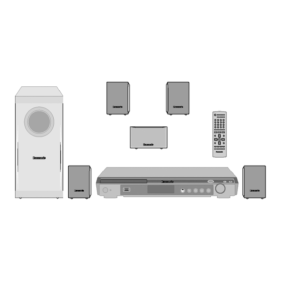
DVD Home Theater Sound System
SA-PT150GC
SA-PT150GCP
SA-PT150GCS
SA-PT150GCT
SA-PT150GS
Colour
(S).......................Silver Type
lFront Ch:
lCenter Ch:
lSurround Ch:
At 100 Hz and total harmonic of 1%
lSubwoofer Ch:
lFM TUNER, TERMINALS SECTION
Preset Memory:
Frequency Modulation (FM)
Frequency range:
Sensitivity:
S/N 26 dB:
Antenna terminals:
Mic Jack:
Sensitivity:
Terminal:
lUSB SECTION
USB Port:
USB standard:
Media file format support:
© 2007 Matsushita Electric Industrial Co., Ltd. All
rights
reserved.
distribution is a violation of law.
ORDER NO. MD0705010CE
25 W / Channel (5 Ω)
25 W / Channel (5 Ω)
25 W / Channel (5 Ω)
25 W / Channel (5 Ω)
FM 30 stations
87.50-108.00 MHz
(50-kHz step)
1.8 µV (IHF)
1.4 µV
75 Ω (unbalanced)
0.7 mV (1.2 kΩ)
Mono, 6.3 mm jack (1 system)
USB 2.0 full speed
MP3 (*.mp3)
WMA (*.wma)
JPEG (*.Jpg, *.JPEG)
MPEG4 (*.asf)
Unauthorized
copying
and
Advertisement
Table of Contents
Troubleshooting

Related Manuals for Panasonic SA-PT150GCP


Summary of Contents for Panasonic SA-PT150GCP
-
Page 1: Specifications
ORDER NO. MD0705010CE DVD Home Theater Sound System SA-PT150GC SA-PT150GCP SA-PT150GCS SA-PT150GCT SA-PT150GS Colour (S).......Silver Type Specifications 25 W / Channel (5 Ω) lFront Ch: lGENERAL 25 W / Channel (5 Ω) Power Supply: AC 110 to 240 V, 50/60 Hz lCenter Ch: 25 W / Channel (5 Ω) - Page 2 SA-PT150GC / SA-PT150GCP / SA-PT150GCS / SA-PT150GCT / SA-PT150GS USB device file system: FAT12 lTerminal: Pin jack (Y: green, P : blue, FAT16 : red) (1 system) FAT32 Note: USB Port power: 500 mA (Max) 1. Specifications are subject to change without notice.
- Page 3 SA-PT150GC / SA-PT150GCP / SA-PT150GCS / SA-PT150GCT / SA-PT150GS CONTENTS Page Page 1 Safety Precautions 1.2. Before Repair and Adjustment (Using SMPS Module 1.1. GENERAL GUIDELINES P.C.B.) 1.3. Protection Circuitry...
-
Page 4: Table Of Contents
SA-PT150GC / SA-PT150GCP / SA-PT150GCS / SA-PT150GCT / SA-PT150GS 1.4. Safety Parts Information 11.3. Checking & Repairing Main P.C.B. 1.5. Caution for AC Cord 11.4. Checking & Repairing SMPS Module P.C.B. 2 Prevention of Electro Static Discharge (ESD) to 11.5. Checking & Repairing DVD Module P.C.B. -
Page 5: Safety Precautions
SA-PT150GC / SA-PT150GCP / SA-PT150GCS / SA-PT150GCT / SA-PT150GS 1 Safety Precautions 1.1. GENERAL GUIDELINES 1. When servicing, observe the original lead dress. If a short circuit is found, replace all parts which have been overheated or damaged by the short circuit. -
Page 6: Safety Parts Information
SA-PT150GC / SA-PT150GCP / SA-PT150GCS / SA-PT150GCT / SA-PT150GS The function of this circuitry is to prevent circuitry damage if, for example, the positive and negative speaker connection wires are “shorted”, or if speaker systems with an impedance less than the indicated rated impedance of the amplifier are used. -
Page 7: Caution For Ac Cord
SA-PT150GC / SA-PT150GCP / SA-PT150GCS / SA-PT150GCT / SA-PT150GS 1.5. Caution for AC Cord (For Saudi Arabia and Kuwait) WARNING: DO NOT CONNECT EITHER WIRE TO THE EARTH TERMINAL WHICH IS MARKED WITH THE LETTER ("GS" area code model only) -
Page 8: Prevention Of Electro Static Discharge (Esd) To
SA-PT150GC / SA-PT150GCP / SA-PT150GCS / SA-PT150GCT / SA-PT150GS 2 Prevention of Electro Static Discharge (ESD) to Electrostatically Sensitive (ES) Devices Some semiconductor (solid state) devices can be damaged easily by static electricity. Such components commonly are called Electrostatically Sensitive (ES) Devices. Examples of typical ES devices are integrated circuits and some field-effect transistors and semiconductor "chip"... -
Page 9: Precaution Of Laser Diode
SA-PT150GC / SA-PT150GCP / SA-PT150GCS / SA-PT150GCT / SA-PT150GS 3 Precaution of Laser Diode CAUTION : This product utilizes a laser diode with the unit turned on, invisible laser radiation is emitted from the pickup lens. Wavelength : 662nm/785nm Maximum output radiation power from pickup : 100µW/VDE Laser radiation from pickup unit is safety level, but be sure the followings: 1. -
Page 10: Service Caution Based On Legal Restrictions
SA-PT150GC / SA-PT150GCP / SA-PT150GCS / SA-PT150GCT / SA-PT150GS 4 About Lead Free Solder (PbF) 4.1. Service caution based on legal restrictions 4.1.1. General description about Lead Free Solder (PbF) The lead free solder has been used in the mounting process of all electrical components on the printed circuit boards used for this equipment in considering the globally environmental conservation. -
Page 11: Handling Precautions For Traverse Unit
SA-PT150GC / SA-PT150GCP / SA-PT150GCS / SA-PT150GCT / SA-PT150GS 5 Handling Precautions for Traverse Unit The laser diode in the optical pickup unit may break down due to static electricity of clothes or human body. Special care must be taken avoid caution to electrostatic breakdown when servicing and handling the laser diode. - Page 12 SA-PT150GC / SA-PT150GCP / SA-PT150GCS / SA-PT150GCT / SA-PT150GS...
- Page 13 SA-PT150GC / SA-PT150GCP / SA-PT150GCS / SA-PT150GCT / SA-PT150GS 6 Accessories Antenna wire Remote control Speaker label AC cord (For GC/GCP/GCS/GCT areas) Video cable AC cord (For GS area only) AC plug adaptor...
-
Page 14: Operation Procedures
SA-PT150GC / SA-PT150GCP / SA-PT150GCS / SA-PT150GCT / SA-PT150GS 7 Operation Procedures 7.1. Remote Control Key Buttons Operations Television operations Adjust the television volume Switch the main unit on or off Select the source DVD: DVD/CD EXT-IN: AUX, USB Change the television’s video input mode Show the current disc’s playback... -
Page 15: Main Unit Key Buttons Operations
SA-PT150GC / SA-PT150GCP / SA-PT150GCS / SA-PT150GCT / SA-PT150GS 7.2. Main Unit Key Buttons Operations Standby/on switch [ /I] Press to switch the unit from on to standby mode or vice versa. In standby mode, the unit is still consuming a small amount of power. -
Page 16: About Divx Vod Content
SA-PT150GC / SA-PT150GCP / SA-PT150GCS / SA-PT150GCT / SA-PT150GS 7.3. About DivX VOD Content DivX Video-on-Demand (VOD) content is encrypted for If you purchase DivX VOD content using a registration copyright protection. In order to play DivX VOD content on code different from this unit’s code, you will not be able... -
Page 17: Usb Connection And Operation
SA-PT150GC / SA-PT150GCP / SA-PT150GCS / SA-PT150GCT / SA-PT150GS 7.4. USB Connection and Operation Optional Optional USB connection and operation USB connection and operation Adjust the volume of the main unit. The USB connectivity enables you to connect and play tracks or files f rom USB mass storage class devices. -
Page 18: Audio And Video Connections
SA-PT150GC / SA-PT150GCP / SA-PT150GCS / SA-PT150GCT / SA-PT150GS 7.5. Audio and Video Connections 7.5.1. Television with Video In Terminal 7.5.2. Television with Component Video In Terminals 7.5.3. Audio Connection for Video Cassette Recorder or Television... - Page 19 SA-PT150GC / SA-PT150GCP / SA-PT150GCS / SA-PT150GCT / SA-PT150GS 7.5.4. Connection for Set Top Box...
-
Page 20: Disc Information
Closing the session will also work. MPEG4 data recorded with the Panasonic SD multi cameras or DVD video recorders [conforming to SD VIDEO specifications (ASF standard)/MPEG4 (Simple Profi le) video system/G.726 audio system]. -
Page 21: Tips For Making Data Discs
You can play MPEG4 data [conforming to SD VIDEO speci c fi ations (ASF standard)/MPEG4 (Simple Pro le) video system/G.726 audio system] recorded with Panasonic SD multi cameras or DVD video rec orders with this unit. The recording date may differ from that of the actual date. -
Page 22: Service Mode Summary Table
SA-PT150GC / SA-PT150GCP / SA-PT150GCS / SA-PT150GCT / SA-PT150GS 8 Self-Diagnosis and Special Mode Setting 8.1. Service Mode Summary Table The service modes can be activated by pressing various button combination on the main unit and remote control unit. Below is the summary for the various modes for checking:... -
Page 23: Service Mode Table
SA-PT150GC / SA-PT150GCP / SA-PT150GCS / SA-PT150GCT / SA-PT150GS 8.2.1. Service Mode Table 1 Item Key Operation FL Display Mode Name Description Front Key Jitter check Jitter check. In STOP (no disc) mode, (Display 1) Jitter rate is measured and displayed. - Page 24 SA-PT150GC / SA-PT150GCP / SA-PT150GCS / SA-PT150GCT / SA-PT150GS 8.2.2. Service Mode Table 2 Key Operation Item FL Display Mode Name Description Front Key (Display 1) DVD laser DVD laser drive current measurement. In STOP (no disc) mode, drive current...
- Page 25 SA-PT150GC / SA-PT150GCP / SA-PT150GCS / SA-PT150GCT / SA-PT150GS 8.2.3. Service Mode Table 3 Item Key Operation FL Display Mode Name Description Front Key Micro-processor Micro-processor firmware version In STOP (no disc) (Display 1) firmware version display & EEPROM checksum display.
- Page 26 SA-PT150GC / SA-PT150GCP / SA-PT150GCS / SA-PT150GCT / SA-PT150GS Product Region TV Broadcasting Model Series Country Region Signal System Region Display Code OSD Menu Language System (Default) (Default) English, Spanish, Canadian P, PC, PX USA, Canada, PX NTSC NTSC (*A)
- Page 27 SA-PT150GC / SA-PT150GCP / SA-PT150GCS / SA-PT150GCT / SA-PT150GS 8.2.4. Service Mode Table 4 Item Key Operation FL Display Mode Name Description Front Key DVD Module P.C.B. firmware version In STOP (no disc) Module P.C.B. is displayed on the FL Display.
- Page 28 SA-PT150GC / SA-PT150GCP / SA-PT150GCS / SA-PT150GCT / SA-PT150GS 8.2.5. Service Mode Table 5 Item Key Operation FL Display Mode Name Description Front Key Timer 1 check Timer 1 check In STOP (no disc) (Display 1) Laser operation timer is measured mode, press [STOP] separately for DVD laser and CD laser.
- Page 29 SA-PT150GC / SA-PT150GCP / SA-PT150GCS / SA-PT150GCT / SA-PT150GS 8.2.6. Optical Pick-up Self-Diagnosis The optical pickup self-diagnosis function and tilt adjustment check function have been included in this unit. When repairing, use the following procedure for effective self-diagnosis and tilt adjustment. Be sure to use the self-diagnosis function before replacing the optical pickup when "NO DISC"...
-
Page 30: Dvd Self Diagnostic Function-Error Code
SA-PT150GC / SA-PT150GCP / SA-PT150GCS / SA-PT150GCT / SA-PT150GS 8.3. DVD Self Diagnostic Function-Error Code 8.3.1. Mechanism Error Code Table Error Diagnosis Contents Description of error Automatic FL Display Remarks Code H01 Tray loading error The tray opening and closing is... - Page 31 SA-PT150GC / SA-PT150GCP / SA-PT150GCS / SA-PT150GCT / SA-PT150GS 8.3.2. DVD Module Error Code Table Error Diagnosis Contents Description of error Automatic FL Display Remarks Code U702 DVD/DVI I2C The communication error of I2C Press [ STOP] on communication error when connecting it with DVD/ main unit for next error.
- Page 32 SA-PT150GC / SA-PT150GCP / SA-PT150GCS / SA-PT150GCT / SA-PT150GS 8.3.3. Power Supply Error Code Table Error Diagnosis Contents Description of error Automatic FL Display Remarks Code F61 The abnormalities In normal operation, when DCDET2 Press [ STOP] on in an output or power goes to "L" (Low) (Not during POWER main unit for next error.
-
Page 33: Sales Demonstration Lock Function
SA-PT150GC / SA-PT150GCP / SA-PT150GCS / SA-PT150GCT / SA-PT150GS 8.3.5. USB Error Code Table Error Diagnosis Contents Description of error Automatic FL Display Remarks Code F650 USB device: Devices Devices other than the mass storage Press [ STOP] on other than mass class are connected. -
Page 34: Service Precautions
SA-PT150GC / SA-PT150GCP / SA-PT150GCS / SA-PT150GCT / SA-PT150GS 8.5. Service Precautions 8.5.1. Recovery after the DVD player is repaired · When the FLASH ROM IC or DVD Module P.C.B. is replaced, carry out the recovery processing to optimize the drive. -
Page 35: Assembling And Disassembling
SA-PT150GC / SA-PT150GCP / SA-PT150GCS / SA-PT150GCT / SA-PT150GS 9 Assembling and Disassembling “ATTENTION SERVICER” Be careful when disassembling and servicing. Some chassis components may have sharp edges. Special Note: 1. This section describes the disassembly procedures for all the major printed circuit boards and main components. -
Page 36: Disassembly Flow Chart
SA-PT150GC / SA-PT150GCP / SA-PT150GCS / SA-PT150GCT / SA-PT150GS · SMPS Module P.C.B. Replacement: 1. This model uses SMPS Module P.C.B. to provide the necessary supply voltages for the unit. 2. It is advisable to replace the SMPS Module P.C.B. once upon detecting of non-working conditions. Do not attempt to repair or replace it by components. -
Page 37: Main Components And P.c.b. Locations
SA-PT150GC / SA-PT150GCP / SA-PT150GCS / SA-PT150GCT / SA-PT150GS 9.2. Main Components and P.C.B. Locations... -
Page 38: Disassembly Of Top Cabinet
SA-PT150GC / SA-PT150GCP / SA-PT150GCS / SA-PT150GCT / SA-PT150GS 9.3. Disassembly of Top Cabinet Step 1 Remove 4 screws. Step 2 Remove 3 screws at the rear panel Step 3 Lift up and remove the top cabinet. Step 2 Insert the gear jig into the tray open/ close hole. -
Page 39: Disassembly Of Front Panel
SA-PT150GC / SA-PT150GCP / SA-PT150GCS / SA-PT150GCT / SA-PT150GS Note: You can return the tray by turning the gear jig clockwise. Step 6 Detach USB shield wire from the connector (CN8000) on USB P.C.B. 9.5. Disassembly of Front Panel Step 7 Remove the front panel. -
Page 40: Disassembly Of Mic P.c.b
SA-PT150GC / SA-PT150GCP / SA-PT150GCS / SA-PT150GCT / SA-PT150GS 9.8. Disassembly of Mic P.C.B. · Follow (Step 1) to (Step 3) of Item 9.3. Step 2 Remove 4 screws from Volume P.C.B.. · Follow (Step 1) to (Step 4) of Item 9.4. -
Page 41: Disassembly Of Rear Panel
SA-PT150GC / SA-PT150GCP / SA-PT150GCS / SA-PT150GCT / SA-PT150GS Step 1 Remove 2 screws from the DVD mechanism unit. Step 2 Detach FFC cable from the connectors (CN2001) on Main P.C.B. and (CS901) on Tray Loading P.C.B. 9.10. Disassembly of Rear panel ·... - Page 42 SA-PT150GC / SA-PT150GCP / SA-PT150GCS / SA-PT150GCT / SA-PT150GS 9.13. Disassembly of USB Relay P.C.B. · Follow (Step 1) to (Step 3) of Item 9.3. · Follow (Step 1) to (Step 4) of Item 9.4. · Follow (Step 1) to (Step 4) of Item 9.11.
- Page 43 SA-PT150GC / SA-PT150GCP / SA-PT150GCS / SA-PT150GCT / SA-PT150GS Step 4 Detach FFC cable from the connectors (CN2 & CN3) on SMPS Module P.C.B., (CN2001,CN2005, CN2006 & CN2007) Step 2 Remove 2 screws from the digital amp IC (IC5100). on Main P.C.B. and (CS901) on Tray Loading P.C.B.
-
Page 44: Disassembly Of Smps Module
SA-PT150GC / SA-PT150GCP / SA-PT150GCS / SA-PT150GCT / SA-PT150GS Step 2 Remove 1 screw from the regulator IC (IC2903). Step 2 Detach FFC cable from the connectors (CN2 & CN3) on Step 3 Remove the regulator IC (IC2903) from the heatsink SMPS Module P.C.B. -
Page 45: Disassembly Procedure
SA-PT150GC / SA-PT150GCP / SA-PT150GCS / SA-PT150GCT / SA-PT150GS 10 Assembly and Disassembly of DVD Mechanism Unit 10.1. Disassembly Procedure Step 4 Remove the traverse unit. 10.1.1. Disassembly of Traverse Unit (with Middle Chassis) Step 1 Slide the lever (A) in the arrow direction (to the opposite side) till it stops. - Page 46 SA-PT150GC / SA-PT150GCP / SA-PT150GCS / SA-PT150GCT / SA-PT150GS l(Assembly of the tray unit) Step 2 Raise the mecha chassis vertically. Step 1 Insert a part of the tray into the unit sliding over the Step 3 Slide the lever in the arrow direction till it stops and pull groove on the mecha chassis.
- Page 47 SA-PT150GC / SA-PT150GCP / SA-PT150GCS / SA-PT150GCT / SA-PT150GS Step 4 Remove the belt. Step 5 Unlock the tab and remove the pulley gear. 10.1.3. Disassembly of Loading Section Step 6 Remove the relay gear. Step 1 Spread the tabs at the both sides and push out the drive arm.
-
Page 48: Disassembly Of Traverse Unit
SA-PT150GC / SA-PT150GCP / SA-PT150GCS / SA-PT150GCT / SA-PT150GS Step 9 Pull the lever (B) at the bottom side in the direction of arrow and remove the change lever. 10.1.5. Disassembly of Traverse Unit Step 1 Spread the tabs to push in the pin in the direction of arrows. - Page 49 SA-PT150GC / SA-PT150GCP / SA-PT150GCS / SA-PT150GCT / SA-PT150GS Step 3 Remove the middle chassis. Step 4 Remove the traverse unit.
-
Page 50: Service Position
SA-PT150GC / SA-PT150GCP / SA-PT150GCS / SA-PT150GCT / SA-PT150GS 11 Service Position 11.3. Checking & Repairing Main P.C.B. 11.1. Checking & Repairing Panel Step 1 Remove the top cabinet. P.C.B. Step 2 Remove the DVD lid. Step 1 Remove the top cabinet. -
Page 51: Module P.c.b
SA-PT150GC / SA-PT150GCP / SA-PT150GCS / SA-PT150GCT / SA-PT150GS 11.5. Checking & Repairing DVD Module P.C.B. · Follow (Step 1) to (Step 14) of Item 11.3. Step 1 Turn over the DVD mechanism unit according to the diagram shown below. -
Page 52: Measurements And Adjustments
SA-PT150GC / SA-PT150GCP / SA-PT150GCS / SA-PT150GCT / SA-PT150GS 12 Measurements and Adjustments 12.1. Service Tools and Equipment Application Name Number Tilt adjustment DVD test disc DVDT-S20 [SPG] TORX screw driver (T6) Available on sales route. (T6) or RFKZ0185 [SPG]... -
Page 53: Optical Adjustment
SA-PT150GC / SA-PT150GCP / SA-PT150GCS / SA-PT150GCT / SA-PT150GS 12.4. Optical adjustment 12.4.1. Optical pickup tilt adjustment Measurement point Adjustment point Mode Disc Tangential adjustment screw T01 (inner periphery) play DVDT-S20 [SPG] Tilt adjustment screw T30 (center periphery) T43 (outer periphery) play... - Page 54 SA-PT150GC / SA-PT150GCP / SA-PT150GCS / SA-PT150GCT / SA-PT150GS 13 Abbreviations INITIAL/LOGO ABBREVIATIONS ERROR TORQUE CONTROL ERROR TORQUE CONTROL INITIAL/LOGO ABBREVIATIONS REFERENCE A0~UP ADDRESS ENCSEL ENCODER SELECT ACLK AUDIO CLOCK ETMCLK EXTERNAL M CLOCK (81MHz/40.5MHz) AD0~UP ADDRESS BUS ETSCLK EXTERNAL S CLOCK (54MHz)
- Page 55 SA-PT150GC / SA-PT150GCP / SA-PT150GCS / SA-PT150GCT / SA-PT150GS INITIAL/LOGO ABBREVIATIONS INITIAL/LOGO ABBREVIATIONS READ ENABLE VBLANK V BLANKING RFENV RF ENVELOPE COLLECTOR POWER SUPPLY RF PHASE DIFFERENCE OUTPUT VOLTAGE (CD-ROM) REGISTER SELECT VCDCONT VIDEO CD CONTROL (TRACKING RSEL RF POLARITY SELECT...
-
Page 56: Voltage And Waveform Chart
SA-PT150GC / SA-PT150GCP / SA-PT150GCS / SA-PT150GCT / SA-PT150GS 14 Voltage and Waveform Chart 14.1. DVD Module P.C.B. IC8001 Ref No. MODE CD PLAY IC8001 Ref No. MODE CD PLAY IC8001 Ref No. MODE CD PLAY IC8001 Ref No. MODE... - Page 57 SA-PT150GC / SA-PT150GCP / SA-PT150GCS / SA-PT150GCT / SA-PT150GS IC8691 IC8695 IC9003 Ref No. MODE CD PLAY IC9005 Ref No. MODE CD PLAY Q8321 Q8325 Q8331 Q8335 Q8341 Ref No. MODE CD PLAY Q8551 Q8552 Q8561 Q8562 Ref No. MODE CD PLAY Ref No.
-
Page 58: Main P.c.b
SA-PT150GC / SA-PT150GCP / SA-PT150GCS / SA-PT150GCT / SA-PT150GS 14.2. Main P.C.B. IC2004 Ref No. MODE CD PLAY STANDBY IC2018 Ref No. MODE CD PLAY STANDBY IC2018 Ref No. MODE CD PLAY STANDBY IC2018 Ref No. MODE CD PLAY STANDBY IC2018 Ref No. -
Page 59: Panel P.c.b
SA-PT150GC / SA-PT150GCP / SA-PT150GCS / SA-PT150GCT / SA-PT150GS 14.3. Panel P.C.B. Ref No. IC6901 MODE CD PLAY -24.4 -24.4 -24.4 -19.6 -19.8 STANDBY -24.4 -24.4 -24.4 -14.9 -19.6 -12.5 IC6901 Ref No. MODE CD PLAY -24.4 -24.4 -24.3 -17.2 -14.8... -
Page 60: Waveform Chart
SA-PT150GC / SA-PT150GCP / SA-PT150GCS / SA-PT150GCT / SA-PT150GS 14.5. Waveform Chart 14.5.1. Waveform 1 WF No. IC2018-13 (PLAY) WF No. IC2018-15 (PLAY) WF No. IC2102-79,80,81,82 83,84 (PLAY) 200Vp-p(5msec/div) 3.4Vp-p(50nsec/div) 1.4Vp-p(200usec/div) 2Vp-p(200usec/div) WF No. IC2102-96 (PLAY) WF No. IC2102-100 (PLAY) WF No. - Page 61 SA-PT150GC / SA-PT150GCP / SA-PT150GCS / SA-PT150GCT / SA-PT150GS 14.5.2. Waveform 2 WF No. IC8251-12,15,17 (PLAY) WF No. IC8251-14 (PLAY) WF No. IC8421-16,19,20,21 WF No. IC8421-15 (PLAY) 22,26,27 (PLAY) 3.4Vp-p(200usec/div) 0.1Vp-p(200usec/div) 3.4Vp-p(200usec/div) 2Vp-p(200usec/div)
-
Page 62: Illustration Of Ic's, Transistors And Diodes
SA-PT150GC / SA-PT150GCP / SA-PT150GCS / SA-PT150GCT / SA-PT150GS 15 Illustration of IC's, Transistors and Diodes RFKWMHC0B320 C1AB00001731 (6p) C0ABBB000230 (8p) (GC/GCP/GS) C0HBB0000057 (44p) C1BB00001061 (16p) C0CBCBD00018 (8p) RFKWMHC0D320 C1AB00002463 (100p) C0DBZYE00002 (8p) C3ABPG000145 (54p) (GCS/GCT) C9ZB00000461 (32p) C0EBA0000029 (4p) -
Page 63: Wiring Connection Diagram
SA-PT150GC / SA-PT150GCP / SA-PT150GCS / SA-PT150GCT / SA-PT150GS 16 Wiring Connection Diagram CP2010 JK2002 PANEL P.C.B. TUNER EXTENT P.C.B. CN2002 Z6900 (SOLDER SIDE) (SOLDER SIDE) VIDEO OUT CN2010 CN6001 COMPONENT VIDEO OUT SENSOR TO TUNER PACK UNIT H6004 VR6800 VOLUME P.C.B. - Page 64 SA-PT150GC / SA-PT150GCP / SA-PT150GCS / SA-PT150GCT / SA-PT150GS...
-
Page 65: Block Diagram
SA-PT150GC / SA-PT150GCP / SA-PT150GCS / SA-PT150GCT / SA-PT150GS 17 Block Diagram 17.1. System Control FL6901 IC2018 C2CBYY000438 CN6001 CN2007 FL DISPLAY SYSTEM CONTROL FROM CN6001 CN2007 AMP & POWER IC6901 VREF C0HBB0000057 DISPLAY DRIVER S901 PLAY CS901 H2004 TRAY CLOSE... -
Page 66: Dvd (Servo)
SA-PT150GC / SA-PT150GCP / SA-PT150GCS / SA-PT150GCT / SA-PT150GS 17.2. DVD (Servo) : CD HEAD SIGNAL LINE : DVD RF SIGNAL LINE : TRACKING ERROR SIGNAL LINE : DVD HEAD SIGNAL LINE : MOTOR DRIVE SIGNAL LINE : FOCUS ERROR SIGNAL LINE... -
Page 67: Dvd (Audio)
SA-PT150GC / SA-PT150GCP / SA-PT150GCS / SA-PT150GCT / SA-PT150GS 17.3. DVD (Audio) : DVD RF SIGNAL LINE : DVD AUDIO SIGNAL LINE : MAIN SIGNAL LINE : USB SIGNAL LINE IC8421 IC8001 C0FBBK000050 MN2DS0018MP AUDIO DAC DV5.0 LSI OPTICAL PIC-UP UNIT... - Page 68 SA-PT150GC / SA-PT150GCP / SA-PT150GCS / SA-PT150GCT / SA-PT150GS 17.4. DVD (Video) : DVD VIDEO SIGNAL LINE : MAIN SIGNAL LINE IC8001 IC2801 MN2DS0018MP C9ZB00000461 DV5.0 LSI VIDEO BUFFER IC2802 C1AB00001731 VIDEO BUFFER BIAS Q8331 Y/PY/G FP8101 CN2001 CY IN...
- Page 69 SA-PT150GC / SA-PT150GCP / SA-PT150GCS / SA-PT150GCT / SA-PT150GS 17.5. Audio :MAIN SIGNAL LINE :FM SIGNAL LINE :AUX, MIC SIGNAL LINE IC2102 C1AB00002463 AUDIO SIGNAL PROCESSOR JK1001 21PIN JACK RECOUTL LINEOUT L RECOUTR LINEOUT R TV LCH INL3 TV RCH...
-
Page 70: Amp & Power
SA-PT150GC / SA-PT150GCP / SA-PT150GCS / SA-PT150GCT / SA-PT150GS 17.6. Amp & Power :MAIN SIGNAL LINE IC5100 AN17831A SPEAKERS POWER FRONT L CH2 + FR0NT +L FRONT +LOUT OUTPUT JK5000 IC8111 CH2 INPUT FRONT L FRONT -LOUT C0CBCBD00018 JK5000 +3.3V DC-DC CONVERTER... -
Page 71: Schematic Diagram Notes
SA-PT150GC / SA-PT150GCP / SA-PT150GCS / SA-PT150GCT / SA-PT150GS 18 Schematic Diagram Notes : DVD Video signal line : CD Head signal line · This schematic diagram may be modified at any time with the development of new technology. : DVD Head signal line... - Page 72 SA-PT150GC / SA-PT150GCP / SA-PT150GCS / SA-PT150GCT / SA-PT150GS...
-
Page 73: Schematic Diagram
SA-PT150GC / SA-PT150GCP / SA-PT150GCS / SA-PT150GCT / SA-PT150GS 19 Schematic Diagram 19.1. DVD Module Circuit SCHEMATIC DIAGRAM - 1 : CD HEAD SIGNAL LINE : DVD RF SIGNAL LINE : DVD AUDIO SIGNAL LINE : FOCUS ERROR SIGNAL LINE... -
Page 74: Dvd Module Circuit
SA-PT150GC / SA-PT150GCP / SA-PT150GCS / SA-PT150GCT / SA-PT150GS SCHEMATIC DIAGRAM - 2 DVD MODULE CIRCUIT : +B SIGNAL LINE : DVD AUDIO SIGNAL LINE : DVD VIDEO SIGNAL LINE : MAIN SIGNAL LINE : USB SIGNAL LINE FP8101 VGND... - Page 75 SA-PT150GC / SA-PT150GCP / SA-PT150GCS / SA-PT150GCT / SA-PT150GS SCHEMATIC DIAGRAM - 3 DVD MODULE CIRCUIT : +B SIGNAL LINE : MOTOR DRIVE SIGNAL LINE : DVD RF SIGNAL LINE : DVD AUDIO SIGNAL LINE TO DVD MODULE SECTION (1/4)
- Page 76 SA-PT150GC / SA-PT150GCP / SA-PT150GCS / SA-PT150GCT / SA-PT150GS SCHEMATIC DIAGRAM - 4 : CD HEAD SIGNAL LINE : MOTOR DRIVE SIGNAL LINE : DVD RF SIGNAL LINE DVD MODULE CIRCUIT : +B SIGNAL LINE : DVD HEAD SIGNAL LINE...
- Page 77 SA-PT150GC / SA-PT150GCP / SA-PT150GCS / SA-PT150GCT / SA-PT150GS 19.2. Main Circuit SCHEMATIC DIAGRAM - 5 :-B SIGNAL LINE MAIN CIRCUIT :+B SIGNAL LINE :MAIN SIGNAL LINE :AUX / MIC SIGNAL LINE R7107 IC7100 C1BB00001061 ECHO_MUTE DIGITAL DELAY ECHO_LV2 SW+5V...
- Page 78 SA-PT150GC / SA-PT150GCP / SA-PT150GCS / SA-PT150GCT / SA-PT150GS SCHEMATIC DIAGRAM - 6 :-B SIGNAL LINE MAIN CIRCUIT :+B SIGNAL LINE :MAIN SIGNAL LINE :FM SIGNAL LINE :DVD VIDEO SIGNAL LINE :AUX / MIC SIGNAL LINE R2427 CHASSIS VREF W4055...
- Page 79 SA-PT150GC / SA-PT150GCP / SA-PT150GCS / SA-PT150GCT / SA-PT150GS SCHEMATIC DIAGRAM - 7 :-B SIGNAL LINE MAIN CIRCUIT :+B SIGNAL LINE :MAIN SIGNAL LINE :FM SIGNAL LINE :AUX / MIC SIGNAL LINE :DVD VIDEO SIGNAL LINE Q2801 B1GBCFJJ0051 C2808 TO MAIN...
- Page 80 SA-PT150GC / SA-PT150GCP / SA-PT150GCS / SA-PT150GCT / SA-PT150GS SCHEMATIC DIAGRAM - 8 :-B SIGNAL LINE MAIN CIRCUIT :+B SIGNAL LINE :MAIN SIGNAL LINE TO MAIN IC5100 SECTION (2/4) AN17831A POWER FR+_OUT M+9V 300mA +9.1V C5124 FR-_OUT SW+5V 15mA C5105...
- Page 81 SA-PT150GC / SA-PT150GCP / SA-PT150GCS / SA-PT150GCT / SA-PT150GS 19.3. Tuner Extent, Panel & Volume Circuit SCHEMATIC DIAGRAM - 9 :+B SIGNAL LINE TUNER EXTENT CIRCUIT PANEL CIRCUIT :FM SIGNAL LINE :+B SIGNAL LINE :-B SIGNAL LINE CP2010 CN2010 FL6901...
- Page 82 SA-PT150GC / SA-PT150GCP / SA-PT150GCS / SA-PT150GCT / SA-PT150GS 19.4. Mic, USB Relay, USB, Tray Loading & Optical Pickup Unit Circuit SCHEMATIC DIAGRAM - 10 :-B SIGNAL LINE MIC CIRCUIT USB RELAY CIRCUIT :USB SIGNAL LINE :+B SIGNAL LINE :MIC SIGNAL LINE...
- Page 83 SA-PT150GC / SA-PT150GCP / SA-PT150GCS / SA-PT150GCT / SA-PT150GS SCHEMATIC DIAGRAM - 11 OPTICAL PICKUP UNIT CIRCUIT (FOR REFERENCE ONLY) TO ACT TO HFM GND(Im) DVD MODULE CIRCUIT (FP8531) VREF2(RF-) PIN(DVD) IN SCHEMATIC LD(CD) DIAGRAM - 4 LD GND LD(DVD)
- Page 84 SA-PT150GC / SA-PT150GCP / SA-PT150GCS / SA-PT150GCT / SA-PT150GS...
-
Page 85: Printed Circuit Board
SA-PT150GC / SA-PT150GCP / SA-PT150GCS / SA-PT150GCT / SA-PT150GS 20 Printed Circuit Board 20.1. DVD Module P.C.B. DVD MODULE P.C.B (REPX0562A...GC/GS/GCP) (REPX0562B...GCS/GCT) FP8531 (TO OPTICAL PICKUP UNIT) C8258 C8256 R8263 C8262 C8530 LB8530 R8261 C8257 IC8251 C8254 C8572 R8533 RX8534... - Page 86 SA-PT150GC / SA-PT150GCP / SA-PT150GCS / SA-PT150GCT / SA-PT150GS 20.2. Main P.C.B. MAIN P.C.B. (REPX0581D...GCS/GCT, REPX0581E...GC/GS, REPX0581F...GCP) C2809 W2258 L2801 W2282 Q2801 CN2002 W4017 C2810 W2032 JK2002 C2807 C2169 R2160 R2803 W2268 C2162 R2161 C2826 IC2801 VIDEO OUT W2267 IC2802...
- Page 87 SA-PT150GC / SA-PT150GCP / SA-PT150GCS / SA-PT150GCT / SA-PT150GS 20.3. Panel, Volume & Tuner Extent P.C.B. PANEL P.C.B. (REPX0581D...GCS/GCT) (REPX0581E...GC/GS) (REPX0581F...GCP) W6513 FL6901 W6012 C6917 W6002 W6011 R6916 R6919 W6001 C6916 R6914 W6004 S6800 C6905 W6010 C6918 C6906 (POWER) W6003...
- Page 88 SA-PT150GC / SA-PT150GCP / SA-PT150GCS / SA-PT150GCT / SA-PT150GS 20.4. Mic, USB, USB Relay & Tray Loading P.C.B. (REPX0581D...GCS/GCT) USB P.C.B. MIC P.C.B. (REPX0581D...GCS/GCT) (REPX0581E...GC/GS) (REPX0581E...GC/GS) (REPX0581F...GCP) (REPX0581F...GCP) VOLUME CN8000 JK6802 VA8002 CN8001 R6081 VR6081 (TO USB) VA8001 R6701 R6708...
-
Page 89: Basic Troubleshooting Guide
SA-PT150GC / SA-PT150GCP / SA-PT150GCS / SA-PT150GCT / SA-PT150GS 21 Basic Troubleshooting Guide 21.1. Basic Troubleshooting Guide for Traverse Unit (DVD Module P.C.B) Problems Checking Points Checking Components 1) Distorted picture or a) Check SDRAM address, IC8051 abnormal sound is head... -
Page 90: Basic Troubleshooting Guide For Smps/Main/Panel
SA-PT150GC / SA-PT150GCP / SA-PT150GCS / SA-PT150GCT / SA-PT150GS 21.2. Basic Troubleshooting Guide for SMPS/MAIN/PANEL Problems Checking Points Checking Components 1) No power supply to unit a) Check AC cord connection (open/short) b) Check fuse F1 on SMPS Module P.C.B. -
Page 91: Overall Block Diagram For Pt
SA-PT150GC / SA-PT150GCP / SA-PT150GCS / SA-PT150GCT / SA-PT150GS 22 Overall Block Diagram for PT150 22.1. SC-PT150 Simplified Block... -
Page 92: Terminal Function Of Ics
SA-PT150GC / SA-PT150GCP / SA-PT150GCS / SA-PT150GCT / SA-PT150GS 23 Terminal Function of ICs 23.1. IC2018 (C2CBYY000438): Terminal Name Function System Control IC 55 NC No Connection 56 NC No Connection Terminal Name Function 57 NC No Connection 58 NC... -
Page 93: Exploded Views
SA-PT150GC / SA-PT150GCP / SA-PT150GCS / SA-PT150GCT / SA-PT150GS 24 Exploded Views... - Page 94 SA-PT150GC / SA-PT150GCP / SA-PT150GCS / SA-PT150GCT / SA-PT150GS...
- Page 95 SA-PT150GC / SA-PT150GCP / SA-PT150GCS / SA-PT150GCT / SA-PT150GS 24.1. Cabinet Parts Location...
- Page 96 SA-PT150GC / SA-PT150GCP / SA-PT150GCS / SA-PT150GCT / SA-PT150GS...
- Page 97 SA-PT150GC / SA-PT150GCP / SA-PT150GCS / SA-PT150GCT / SA-PT150GS 24.2. Packaging...
-
Page 98: Replacement Parts List
SA-PT150GC / SA-PT150GCP / SA-PT150GCS / SA-PT150GCT / SA-PT150GS 25 Replacement Parts List Notes: · Important safety notice: Components identified by mark have special characteristics important for safety purpose. Furthermore, special parts which have purposes of fire-retardant (resistors), high-quality sound (capacitors), low-noise (resistors), etc. -
Page 99: Component Parts List
SA-PT150GC / SA-PT150GCP / SA-PT150GCS / SA-PT150GCT / SA-PT150GS 25.1. Component Parts List Ref. Part No. Part Name & Description Remarks XTN26+6GFJ SCREW Ref. Part No. Part Name & Description Remarks XTV2+6GFJ PCB SCREW XWG6FFJ WASHER CABINET AND CHASSIS RMC0387... - Page 100 SA-PT150GC / SA-PT150GCP / SA-PT150GCS / SA-PT150GCT / SA-PT150GS Ref. Part No. Part Name & Description Remarks Ref. Part No. Part Name & Description Remarks Q3008 B1ABGC000005 TRANSISTOR S6806 EVQ21405R SW SELECTOR Q3009 B1ABCF000176 TRANSISTOR Q5740 B1BACG000023 TRANSISTOR CONNECTORS Q5741...
- Page 101 SA-PT150GC / SA-PT150GCP / SA-PT150GCS / SA-PT150GCT / SA-PT150GS Ref. Part No. Part Name & Description Remarks Ref. Part No. Part Name & Description Remarks LB8428 ERJ2GE0R00X CHIP RESISTOR K2CQ2CA00002 AC CORD LB8429 ERJ2GE0R00X CHIP RESISTOR K2CQ2CA00007 AC CORD LB8430...
- Page 102 SA-PT150GC / SA-PT150GCP / SA-PT150GCS / SA-PT150GCT / SA-PT150GS Ref. Part No. Part Name & Description Remarks Ref. Part No. Part Name & Description Remarks R2078 ERJ3GEYJ472V 4.7K 1/16W R2407 ERJ3GEYJ182V 1.8K 1/16W R2079 ERJ3GEYJ103V 10K 1/16W R2411 ERJ3GEY0R00V 0 1/16W...
- Page 103 SA-PT150GC / SA-PT150GCP / SA-PT150GCS / SA-PT150GCT / SA-PT150GS Ref. Part No. Part Name & Description Remarks Ref. Part No. Part Name & Description Remarks R2999 ERJ3GEYJ223V 22K 1/16W R6934 ERJ3GEYJ470V 47 1/16W R3003 ERJ3GEYJ822V 8.2K 1/16W R6936 ERJ3GEYJ100V 10 1/16W...
- Page 104 SA-PT150GC / SA-PT150GCP / SA-PT150GCS / SA-PT150GCT / SA-PT150GS Ref. Part No. Part Name & Description Remarks Ref. Part No. Part Name & Description Remarks R8554 ERJ2GEJ680X 68 1/32W W2201 ERJ6GEY0R00V CHIP RESISTOR [M]GC/G R8555 ERJ2GEJ2R2X 2.2 1/32W W2202 ERJ3GEY0R00V...
- Page 105 SA-PT150GC / SA-PT150GCP / SA-PT150GCS / SA-PT150GCT / SA-PT150GS Ref. Part No. Part Name & Description Remarks Ref. Part No. Part Name & Description Remarks W6102 ERJ3GEY0R00V CHIP JUMPER [M]GC/G C2264 ECJ1VB1H221K 220P 50V C2265 ECJ1VB1H102K 1000P 50V W6502 ERJ6GEY0R00V...
- Page 106 SA-PT150GC / SA-PT150GCP / SA-PT150GCS / SA-PT150GCT / SA-PT150GS Ref. Part No. Part Name & Description Remarks Ref. Part No. Part Name & Description Remarks C2901 ECA1CM471B 470 16V C6906 ECJ1VC1H101K 100P 50V C2903 ECJ1VB1H103K 0.01 50V C6909 ECJ1VB1H103K 0.01 50V...
- Page 107 SA-PT150GC / SA-PT150GCP / SA-PT150GCS / SA-PT150GCT / SA-PT150GS Ref. Part No. Part Name & Description Remarks Ref. Part No. Part Name & Description Remarks C8254 ECJ0EF1C104Z 0.1 16V C8602 ECJ0EB1C153K 0.015 16V C8255 F2G1C220A037 22 16V C8606 ECJ0EF1C104Z 0.1 16V...