Honda EU 1000i Owner's Manual
Honda generator owner's manual
Hide thumbs
Also See for EU 1000i:
- Owner's manual (96 pages) ,
- Quick start manual (1 page) ,
- Information (28 pages)
Table of Contents
Advertisement
Quick Links
Advertisement
Table of Contents

Related Manuals for Honda EU 1000i


Summary of Contents for Honda EU 1000i
- Page 2 The engine exhaust from this product contains chemicals known to the State of California to cause cancer, birth defects or other reproductive harm. The generator is a potential source of electrical shock if misused. Do not expose the generator to moisture, rain or snow. Do not let the generator get wet, and do not operate it with wet hands.
- Page 3 Congratulations on your selection of a Honda generator. We are certain you will be pleased with your purchase of one of the finest generators on the market. We want to help you get the best results from your new generator and to operate it safely.
- Page 4 A FEW WORDS ABOUT SAFETY Your safety and the safety of others are very important. And using this generator safely is an important responsibility. To help you make informed decisions about safety, we have provided operating procedures and other information on labels and in this manual.
-
Page 5: Table Of Contents
SAFETY Safety Label Locations Safety Information COMPONENT IDENTIFICATION CONTROLS Engine Switch Recoil Starter Fuel Tank Cap Vent Lever Choke Lever Output Indicator Light Overload Indicator Light Oil Alert System Ground Terminal EcoThrottle Switch Parallel Operation Outlets DC Receptacle DC Circuit Protector GENERATOR USE Connections to a Building Electrical System Ground System... - Page 6 MAINTENANCE The Importance of Maintenance Maintenance Safety Emission Control System Information Air Index Maintenance Schedule Engine Oil Change Air Cleaner Service Spark Plug Service Spark Arrester Maintenance TRANSPORTING/STORAGE Storage Procedure TROUBLESHOOTING WIRING DIAGRAM INITIAL USE INSTRUCTIONS SPECIFICATIONS TECHNICAL & CONSUMER INFORMATION Customer Service Information Distributor’s Limited Warranty Emission Control System Warranty...
-
Page 7: Safety
SAFETY SAFETY LABEL LOCATIONS These labels warn you of potential hazards that can cause serious injury. Read them carefully. If a label comes off or becomes hard to read, contact your Honda generator dealer for a replacement. -
Page 9: Safety Information
SAFETY INFORMATION Honda generators are designed to give safe and dependable service if operated according to instructions. Read and understand this owner’s manual before operating your generator. You can help prevent accidents by being familiar with your generator’s controls, and by observing safe operating procedures. - Page 10 Electric Shock Hazards The generator produces enough electric power to cause a serious shock or electrocution if misused. Using a generator or electrical appliance in wet conditions, such as rain or snow, or near a pool or sprinkler system, or when your hands are wet, could result in electrocution.
-
Page 11: Component Identification
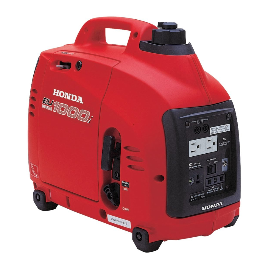
COMPONENT IDENTIFICATION PARALLEL OPERATION OUTLETS AC RECEPTACLES ECOTHROTTLE SWITCH GROUND TERMINAL OIL ALERT INDICATOR LIGHT OVERLOAD INDICATOR LIGHT OUTPUT INDICATOR LIGHT DC RECEPTACLE DC CIRCUIT PROTECTOR FUEL TANK CAP VENT LEVER CHOKE LEVER FUEL TANK CAP RECOIL STARTER GRIP LEFT SIDE MAINTENANCE COVER ENGINE SWITCH... - Page 12 SPARK PLUG MAINTENANCE COVER SPARK PLUG MUFFLER AIR CLEANER FRAME SERIAL NUMBER Record the frame serial number for your future reference. Refer to this serial number when ordering parts, and when making technical or warranty inquiries (see page Frame serial number: Date purchased:...
-
Page 13: Controls
ENGINE SWITCH To start and stop the engine. Switch position: OFF: To stop the engine. To start and run the engine. ENGINE SWITCH RECOIL STARTER To start the engine, pull the starter grip lightly until resistance is felt, then pull briskly. Do not allow the starter grip to snap back against the engine. -
Page 14: Fuel Tank Cap Vent Lever
FUEL TANK CAP VENT LEVER The fuel tank cap is provided with a vent lever to seal the fuel tank. The vent lever must be in the ON position for the engine to run. When the engine is not in use, leave the vent lever in the OFF position to reduce the possibility of fuel leakage. -
Page 15: Output Indicator Light
OUTPUT INDICATOR LIGHT The output indicator light (green) is illuminated when the generator is operating normally. It indicates that the generator is producing electrical power at the receptacles. OVERLOAD INDICATOR LIGHT If the generator is overloaded (in excess of 1,000 VA), or if there is a short circuit in a connected appliance, the overload indicator light (red) will go ON. -
Page 16: Oil Alert System
OIL ALERT SYSTEM The Oil Alert system is designed to prevent engine damage caused by an insufficient amount of oil in the crankcase. Before the oil level in the crankcase can fall below a safe limit, the Oil Alert indicator light comes on and the Oil Alert system automatically will stop the engine (the engine switch will remain in the ON position). -
Page 17: Ecothrottle Switch
ECOTHROTTLE SWITCH The EcoThrottle system automatically reduces engine speed when all loads are turned off or disconnected. When appliances are turned on or reconnected, the engine returns to the proper speed to power the electrical load. If high electrical loads are connected simultaneously, turn the EcoThrottle switch to the OFF position to reduce voltage changes. -
Page 18: Dc Receptacle
DC RECEPTACLE The DC receptacle should ONLY be used for charging 12-volt automotive type batteries. DC CIRCUIT PROTECTOR The DC circuit protector automatically shuts off the DC battery charging circuit when the DC charging circuit is overloaded, when there is a problem with the battery, or when the connections between the battery and the generator are improper. -
Page 19: Generator Use
CONNECTIONS TO A BUILDING ELECTRICAL SYSTEM Connections for standby power to a building electrical system must be made by a qualified electrician. The connection must isolate the generator power from utility power, and must comply with all applicable laws and electrical codes. Improper connections to a building electrical system can allow electrical current from the generator to backfeed into the utility lines. -
Page 20: Ac Applications
AC APPLICATIONS Before connecting an appliance or power cord to the generator: Make sure that it is in good working order. Faulty appliances or power cords can create a potential for electrical shock. If an appliance begins to operate abnormally, becomes sluggish or stops suddenly, turn it off immediately. -
Page 21: Ac Operation
AC OPERATION Start the engine and make sure the output indicator light (green) comes on (see page Plug in the appliance. Most motorized appliances require more than their rated wattage for startup. OUTPUT INDICATOR LIGHT (GREEN) OVERLOAD INDICATOR LIGHT (RED) If the generator is overloaded (in excess of 1,000 VA), or if there is a short circuit in a connected appliance, the overload indicator light (red) will go ON. -
Page 22: Ac Parallel Operation Applications
AC PARALLEL OPERATION APPLICATIONS Follow the instructions included with the parallel operation kit. Before connecting an appliance or power cord to the generator: Make sure that it is in good working order. Faulty appliances or power cords can create a potential for electrical shock. If an appliance begins to operate abnormally, becomes sluggish or stops suddenly, turn it off immediately. - Page 23 Limit operation requiring maximum power to 30 minutes. Maximum power in parallel operation is: 2.0 kVA For continuous operation, do not exceed the rated power. Rated power in parallel operation is: 1.8 kVA In either case, the total power requirements (VA) of all appliances connected must be considered.
-
Page 24: Ac Parallel Operation
AC PARALLEL OPERATION Connect the parallel operation kit between the two EU1000i generators following the instructions supplied with the kit. Start the generators and make sure the output indicator lights (green) come on (see page Plug in the appliance following the instructions provided with the parallel operation kit. -
Page 25: Dc Operation
DC OPERATION The DC receptacle should ONLY be used for charging 12-volt automotive type batteries. When using the DC output, turn the EcoThrottle position. Connecting the battery charging cable (optional equipment): Before connecting the battery charging cable to a battery that is installed in a vehicle, disconnect the vehicle battery ground cable from the negative ( ) battery terminal. -
Page 26: Disconnecting The Battery Charging Cable
Do not start the vehicle while the battery charging cable is connected and the generator is running. The vehicle or the generator may be damaged. An overloaded DC circuit, excessive current draw by the battery, or a wiring problem will trip the DC circuit protector (PUSH button extends out). -
Page 27: Ecothrottle System
ECOTHROTTLE SYSTEM With the switch in the ON position, engine speed is automatically lowered when loads are reduced, turned OFF or disconnected. When appliances are turned ON or reconnected, the engine returns to the proper speed to power the electrical load. In the OFF position, the EcoThrottle system does not operate. -
Page 28: High Altitude Operation
HIGH ALTITUDE OPERATION At high altitude, the standard carburetor air/fuel mixture will be too rich. Performance will decrease, and fuel consumption will increase. A very rich mixture will also foul the spark plug and cause hard starting. Operation at an altitude that differs from that at which this engine was certified, for extended periods of time, may increase emissions. -
Page 29: Pre-Operation Check
ENGINE OIL Engine oil is a major factor affecting engine performance and service life. Non-detergent and 2-stroke engine oils will damage the engine and are not recommended. Check the oil level BEFORE EACH USE with the generator on a level surface and the engine stopped. - Page 30 Remove the oil filler cap and wipe the dipstick clean. Check the oil level by inserting the dipstick into the filler neck without screwing it in. If the level is low, fill to the upper limit of the oil filler neck with the recommended oil.
-
Page 31: Refueling
REFUELING Fuel tank capacity: 0.61 US gal (2.3 ) With the engine stopped, remove the fuel tank cap and check the fuel level. Refill the fuel tank if the fuel level is low. Gasoline is highly flammable and explosive. You can be burned or seriously injured when handling fuel. Stop the engine and keep heat, sparks, and flame away. -
Page 32: Fuel Recommendations
FUEL RECOMMENDATIONS Use unleaded gasoline with a pump octane rating of 86 or higher. This engine is certified to operate on unleaded gasoline. Unleaded gasoline produces fewer engine and spark plug deposits and extends exhaust system life. Never use stale or contaminated gasoline or an oil/gasoline mixture. Avoid getting dirt or water in the fuel tank. - Page 33 Oxygenated Fuels Some conventional gasolines are being blended with alcohol or an ether compound. These gasolines are collectively referred to as oxygenated fuels. To meet clean air standards, some areas of the United States and Canada use oxygenated fuels to help reduce emissions.
-
Page 34: Starting The Engine
STARTING THE ENGINE STARTING THE ENGINE Make sure that all appliances are disconnected from the AC receptacles. Turn the vent lever to the ON position. To start a cold engine, move the choke lever to the CLOSED position. To restart a warm engine, leave the choke lever in the OPEN position. Turn the engine switch to the ON position. -
Page 35: Stopping The Engine
STOPPING THE ENGINE To stop the engine in an emergency, simply turn the engine switch to the OFF position. Under normal conditions, use the following procedure. Unplug appliances from the generator receptacles. Turn the engine switch to the OFF position. The fuel valve will automatically close. -
Page 36: Maintenance
MAINTENANCE THE IMPORTANCE OF MAINTENANCE Good maintenance is essential for safe, economical, and trouble-free operation. It will also help reduce air pollution. Improper maintenance, or failure to correct a problem before operation, can cause a malfunction in which you can be seriously hurt or killed. -
Page 37: Maintenance Safety
MAINTENANCE SAFETY Some of the most important safety precautions follow. However, we cannot warn you of every conceivable hazard that can arise in performing maintenance. Only you can decide whether or not you should perform a given task. Failure to properly follow maintenance instructions and precautions can cause you to be seriously hurt or killed. -
Page 38: Emission Control System Information
EMISSION CONTROL SYSTEM INFORMATION Source of Emissions The combustion process produces carbon monoxide, oxides of nitrogen, and hydrocarbons. Control of hydrocarbons and oxides of nitrogen are very important because, under certain conditions, they react to form photochemical smog when subjected to sunlight. Carbon monoxide does not react in the same way, but it is toxic. - Page 39 Problems That May Affect Emissions If you are aware of any of the following symptoms, have your engine inspected and repaired by your servicing dealer. Hard starting or stalling after starting. Rough idle. Misfiring or backfiring under load. Afterburning (backfiring). Black exhaust smoke or high fuel consumption.
-
Page 40: Air Index
AIR INDEX An Air Index Information hang tag/label is applied to engines certified to an emission durability time period in accordance with the requirements of the California Air Resources Board. The bar graph is intended to provide you, our customer, the ability to compare the emissions performance of available engines. -
Page 41: Maintenance Schedule
MAINTENANCE SCHEDULE REGULAR SERVICE PERIOD (3) ITEM Perform at every indicated month or o per ati ng h our int erv al, whichever comes first. Engine oil Check level Change Air cleaner Check Clean Spark plug Check-adjust Replace Spark arrester Clean Valve clearance Check-adjust... -
Page 42: Engine Oil Change
ENGINE OIL CHANGE Drain the used oil while the engine is warm. Warm oil drains quickly and completely. Turn the engine switch and vent lever to the OFF position to reduce the possibility of fuel leakage. Loosen the cover screw and remove the left-side maintenance cover (see page 27 ). - Page 43 Wash your hands with soap and water after handling used oil. Improper disposal of engine oil can be harmful to the environment. If you change your own oil, please dispose of it properly. Put it in a sealed container, and take it to a recycling center. Do not discard it in a trash bin, dump it on the ground, or pour it down a drain.
-
Page 44: Air Cleaner Service
AIR CLEANER SERVICE A dirty air cleaner will restrict air flow to the carburetor. To prevent carburetor malfunction, service the air cleaner regularly. Service more frequently when operating the generator in extremely dusty areas. Using gasoline or flammable solvent to clean the air filter can cause a fire or explosion. - Page 45 Remove the rubber air guide from the air cleaner case. Clean the air guide and the air cleaner case with a moist rag, then reinstall the air guide. Reinstall the air filter. Make sure that the seal rubber is set in the groove of the air cleaner cover.
-
Page 46: Spark Plug Service
SPARK PLUG SERVICE In order to service the spark plug, you will need a spark plug wrench (commercially available). Recommended spark plugs: To ensure proper engine operation, the spark plug must be properly gapped and free of deposits. An incorrect spark plug can cause engine damage. If the engine has been running, the muffler will be very hot. - Page 47 Visually inspect the spark plug. Discard it if the insulator is cracked or chipped. Measure the spark plug electrode gap with a wire-type feeler gauge. Correct the gap, if necessary, by carefully bending the side electrode. The gap should be: 0.024 0.028 in (0.60 0.70 mm) −...
-
Page 48: Spark Arrester Maintenance
SPARK ARRESTER MAINTENANCE If the generator has been running, the muffler will be very hot. Allow it to cool before proceeding. The spark arrester must be serviced every 100 hours to maintain its efficiency. Clean the spark arrester as follows: Remove the four 5 mm screws, and remove the muffler protector. - Page 49 Use a brush to remove carbon deposits from the spark arrester screen. Inspect the screen for breaks or tears and replace it if necessary. Check the muffler gasket; replace if damaged. Reinstall the muffler gasket, the spark arrester, the muffler and the muffler protector in the reverse order of removal.
-
Page 50: Transporting/Storage
TRANSPORTING/STORAGE TRANSPORTING If the generator has been used, allow it cool for at least 15 minutes before loading the generator on the transport vehicle. A hot engine and exhaust system can burn you and can ignite some material. To prevent fuel spillage when transporting, the generator should be secured upright in its normal operating position, with the engine switch OFF and the fuel tank cap vent lever turned fully counterclockwise to the ‘‘OFF’’position. -
Page 51: Storage Procedure
Storage Procedure Drain the gasoline. Remove the fuel tank cap, and empty the fuel tank into an approved gasoline container using a commercially available hand siphon. Reinstall the fuel tank cap. Loosen the cover screw and remove the left-side maintenance cover. Loosen the carburetor drain screw. - Page 52 Change the engine oil (page 40). Remove the spark plug, and pour about a tablespoon of clean engine oil into the cylinder. Crank the engine several revolutions to distribute the oil, then reinstall the spark plug. Reinstall the spark plug cap on the spark plug securely. Reinstall the spark plug maintenance cover.
-
Page 53: Troubleshooting
When the engine will not start: Is there fuel in the tank? Is there enough oil in the engine? Is the spark plug in good condition? If the engine still does not start, take the generator to an authorized Honda generator dealer. - Page 54 Appliance does not operate: Is the output indicator light ON? I s t h e o v e r l o a d indicator light ON? Check the electrical ap- pliance or equipment for any defects. No electricity at the DC receptacle: Is the DC circuit protector Take the generator to an authorized Honda generator...
-
Page 55: Wiring Diagram
WIRING DIAGRAM... -
Page 56: Initial Use Instructions
INITIAL USE INSTRUCTIONS ADDING ENGINE OIL The generator is shipped Loosen the cover screw and remove the maintenance cover. MAINTENANCE COVER With the generator in a level position, remove the oil filler cap/ dipstick. Add enough SAE 10W-30 API service category SJ or later oil to bring the oil level to the upper limit of the oil filler neck. - Page 57 ADDING FUEL Add fuel to the generator in a well-ventilated area. Never refuel the engine inside a building where gasoline fumes may reach flames or sparks. Keep gasoline away from appliance pilot lights, barbecues, electric appliances, power tools, etc. Spilled fuel is not only a fire hazard, it causes environmental damage.
- Page 58 After refueling, tighten the fuel tank cap securely. Keep the vent OFF for storage or transport, and ON to run the generator. VENT LEVER Move the generator at least 10 feet (3 meters) away from the fueling source and site before starting the engine. After initial fueling (or anytime the generator is run completely out of fuel), starting the engine may require additional pulls of the starter rope.
-
Page 59: Specifications
SPECIFICATIONS Dimensions Model Power product description code Length Width Height Dry weight Engine Model Engine Type Displacement 〔 Bore × Stroke 〕 Compression Ratio Engine Speed Cooling System Ignition System Oil Capacity Fuel Tank Capacity Spark Plug Generator Model Type Rated voltage Rated frequency AC output Rated Ampere... -
Page 60: Technical & Consumer Information
General Manager can help. Almost all problems are solved in this way. If you are dissatisfied with the decision made by the dealership’s management, contact the Honda Power Equipment Customer Relations Office. You can write to: American Honda Motor Co., Inc. -
Page 61: Distributor's Limited Warranty
To Obtain Warranty Service: You must take the Honda generator and proof of original retail purchase date, at your expense, to any Honda Power Equipment dealer in the United States, Puerto Rico, or the U.S. Virgin Islands who is authorized to service that product, during the dealer’s normal business hours. -
Page 62: Emission Control System Warranty
Emission Control System Warranty Your new Honda Power Equipment engine complies with the U.S. EPA, Environment Canada and State of California emission regulations. American Honda Motor Co., Inc. provides the emission warranty coverage for engines in the United States, and its territories. - Page 63 You are responsible for presenting your power equipment engine to a Honda Power Equipment dealer as soon as a problem exists. The warranty repairs should be completed in a reasonable amount of time, not to exceed 30 days.
- Page 64 Alpharetta, Georgia 30005-8847 Telephone: (770) 497-6400 Warranty Coverage: Honda power equipment engines manufactured after January 1, 1995 and sold in the State of California, U.S. EPA certified engines manufactured on or after September 1, 1996 and sold in all of the...
- Page 65 To Obtain Warranty Service: You must take your Honda Power Equipment engine or the product on which it is installed, along with your sales registration card or other proof of original purchase date, at your expense, to any Honda Power Equipment dealer who is authorized by Honda to sell and service that Honda product during his normal business hours.
- Page 66 Disclaimer of Consequential Damage and Limitation of Implied Warranties: AMERICAN HONDA MOTOR CO., INC. AND HONDA CANADA INC. D I S C L A I M A N Y R E S P O N S I B I L I T Y F O R I N C I D E N T A L O R CONSEQUENTIAL DAMAGES SUCH AS LOSS OF TIME OR THE USE OF THE POWER EQUIPMENT, OR ANY COMMERCIAL LOSS DUE TO THE FAILURE OF THE EQUIPMENT;...
-
Page 67: Index
COMPONENT IDENTIFICATION CONTENTS CONTROLS Choke Lever DC Circuit Protector DC Receptacle EcoThrottle System Engine Switch Fuel Tank Cap Vent Lever Ground Terminal Oil Alert System Output Indicator Light Overload Indicator Light Parallel Operation Outlets Recoil Starter CUSTOMER SERVICE INFORMATION GENERATOR USE AC Applications AC Operation AC Parallel Operation... - Page 68 PRE-OPERATION CHECK Engine Oil Fuel Recommendations Refueling SAFETY Safety Information Safety Label Locations SPECIFICATIONS STARTING THE ENGINE STOPPING THE ENGINE TECHNICAL & CONSUMER INFORMATION Customer Service Information Distributor’s Limited Warranty Emission Control System Warranty TRANSPORTING/STORAGE Storage Procedure TROUBLESHOOTING WIRING DIAGRAM .
- Page 69 MEMO...
- Page 70 MEMO...