Honda EU10i Owner's Manual
Hide thumbs
Also See for EU10i:
- Owner's manual (262 pages) ,
- Fitting and operating instructions (4 pages) ,
- Owner's manual (230 pages)
Table of Contents
Advertisement
Advertisement
Table of Contents

Related Manuals for Honda EU10i


Summary of Contents for Honda EU10i
- Page 2 Honda EU10i OWNER’S MANUAL MANUEL DE L’UTILISATEUR BEDIENUNGSANLEITUNG MANUAL DE EXPLICACIONES The‘‘e-SPEC’’mark symbolizes environmentally responsible technologies applied to Honda power equipment, which contains our wish to ‘‘preserve nature for generations to come.’’...
- Page 3 All information in this publication is based on the latest product information available at the time of approval for printing. Honda Motor Co., Ltd. reserves the right to make changes at any time without notice and without incurring any obligation.
-
Page 4: Table Of Contents
Carburetor Modification for High Altitude Operation GENERATOR USE ................25 STOPPING THE ENGINE ..............37 MAINTENANCE ................39 TRANSPORTING/STORAGE ............46 TROUBLESHOOTING ............... 48 SPECIFICATIONS ................50 WIRING DIAGRAM ................52 MAJOR Honda DISTRIBUTOR ADDRESSES ........ . 56... -
Page 5: Safety Instructions
SAFETY INSTRUCTIONS IMPORTANT SAFETY INFORMATION Honda generators are designed for use with electrical equipment that has suitable power requirements. Other uses can result in injury to the operator or damage to the generator and other property. Most injuries or property damage can be prevented if you follow all instructions in this manual and on the generator. - Page 6 Carbon Monoxide Hazards Exhaust contains poisonous carbon monoxide, a colorless, odorless gas. Breathing exhaust can cause loss of consciousness and may lead to death. If you run the generator in an area that is confined, or even partially enclosed area, the air you breathe could contain dangerous amount of exhaust gas.
- Page 7 Fire and Burn Hazards Do not use the generator in areas with a high risk of fire. When installed in ventilated rooms, additional requirements for fire and explosion protection shall be observed. The exhaust system gets hot enough to ignite some materials. Keep the generator at least 1 meter (3 feet) away from buildings and other equipment during operation.
- Page 8 Do not throw it in the trash or pour it on the ground. An improperly disposed battery can hurt the environment. Always confirm local regulations for battery disposal. Contact your Honda servicing dealer for a replacement.
-
Page 9: Safety Label Locations
Read the labels and safety notes and precautions described in this manual carefully. If a label comes off or becomes hard to read, contact your Honda dealer for a replacement. For European model: G, GW, B, F, W types... - Page 10 Honda generator is designed to give safe and dependable service if operated according to instructions. Read and understand the Owner’s Manual before operating the generator. Failure to do so could result in personal injury or equipment damage. Exhaust contains poisonous carbon monoxide, a colorless, odorless gas.
- Page 11 Stop the engine before refueling. Gasoline is extremely flammable and explosive under certain conditions. Refuel in a well ventilated area with the engine stopped. Keep away from cigarette, smoke and sparks when refueling the generator. Always refuel in a well ventilated location. Wipe up spilled gasoline at once.
- Page 12 U type...
-
Page 13: Ce Mark And Noise Label Locations
CE mark and noise label locations G, GW, B, F, W types NOISE LABEL CE MARK Manufacturer and address Performance class IP code Dry mass (weight) -
Page 14: Component Identification
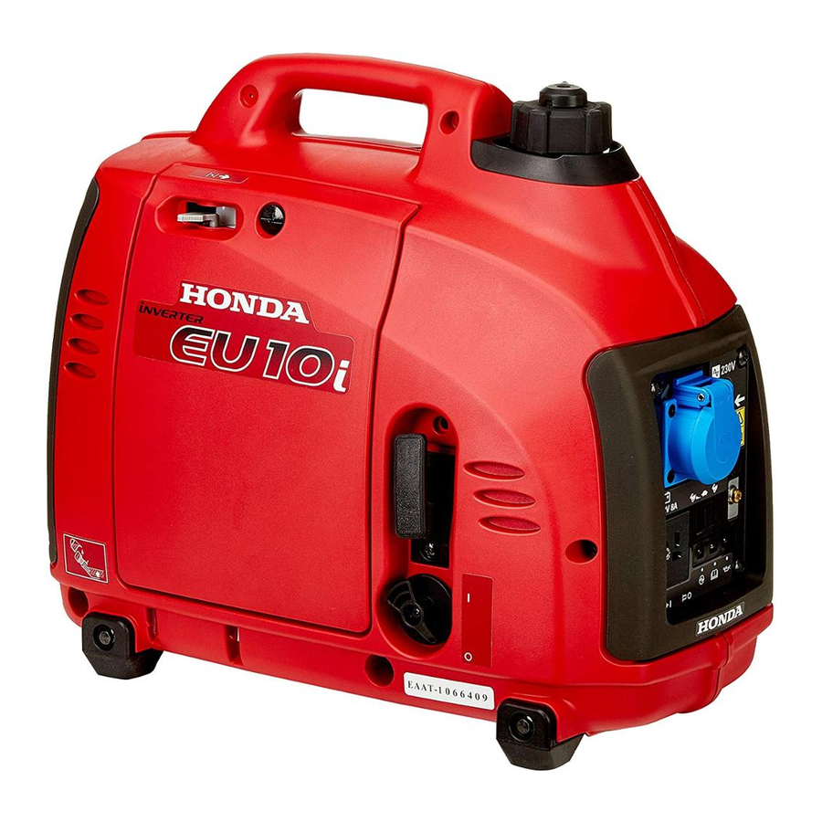
COMPONENT IDENTIFICATION FUEL CAP VENT LEVER CHOKE LEVER FUEL FILLER CAP CONTROL PANEL LEFT SIDE MAINTENANCE COVER STARTER GRIP ENGINE SWITCH FRAME SERIAL NUMBER SPARK PLUG MAINTENANCE COVER MUFFLER Record the frame serial number in the space below. You will need this serial number when ordering parts. -
Page 15: Control Panel
CONTROL PANEL G, GW, B, F, W types AC RECEPTACLE PARALLEL OPERATION SOCKETS ECO THROTTLE SWITCH GROUND TERMINAL OIL ALERT INDICATOR LIGHT OVERLOAD INDICATOR LIGHT OUTPUT INDICATOR LIGHT DC RECEPTACLE DC CIRCUIT PROTECTOR... - Page 16 U type AC RECEPTACLE...
- Page 17 Eco Throttle ECO: Engine speed is kept at idle automatically when the electrical appliance is disconnected and it returns to the proper speed by the electrical load when electrical appliance is connected. This position is recommended to minimize the fuel consumption while in operation. Eco Throttle system does not operate sufficiently if the electrical appliance requires the momentary electric power.
-
Page 18: Pre-Operation Check
PRE-OPERATION CHECK Be sure to check the generator on a level surface with the engine stopped. Check the engine oil level. Using non detergent oil or 2-stroke engine oil could shorten the engine’s service life. Recommended oil Use 4-stroke motor oil that meets or exceeds the requirements for API service category SE or later (or equivalent). - Page 19 Loosen the cover screw and remove the left side maintenance cover. (see page Remove the oil filler cap, and wipe the dipstick with a clean rag. Check the oil level by inserting the dipstick in the filler hole without screwing it in.
- Page 20 Check the fuel level. Check the fuel level. Refill the fuel tank if the fuel level is low. After refueling, tighten the fuel filler cap securely. Use automotive unleaded gasoline with a Research Octane Number of 91 or higher (a Pump Octane Number of 86 or higher). Never use stale or contaminated gasoline or an oil/gasoline mixture.
- Page 21 Gasolines Containing Alcohol If you decide to use a gasoline containing alcohol (gasohol), be sure its octane rating is at least as high as that recommended by Honda. There are two types of ‘‘gasohol’’: one containing ethanol, and the other containing methanol.
- Page 22 Check the air cleaner. Check the air cleaner element to be sure it is clean and in good condition. Loosen the cover screw and remove the left side maintenance cover. Press the latch tab on the top of the air cleaner body, remove the air cleaner cover, check the element.
-
Page 23: Starting The Engine
STARTING THE ENGINE Before starting the engine disconnect any load from the AC receptacle. Turn the fuel cap lever fully clockwise to the ON position. Turn the fuel cap vent lever to the OFF position when transporting the generator. FUEL CAP VENT LEVER Turn the engine switch to the ON position. - Page 24 Move the choke lever to the CLOSED position. Do not use the choke when the engine is warm or the air temperature is high. CHOKE LEVER CLOSED CLOSED Pull the starter grip lightly until you feel resistance, then pull the starter grip briskly toward in the direction of the arrow as shown below.
- Page 25 Move the choke lever to the OPEN position as the engine warms up. CHOKE LEVER OPEN If the engine stops and will not restart, check the engine oil level (see pages ) before troubleshooting in other areas.
- Page 26 High altitude performance can be improved by specific modifications to the carburetor. If you always operate your generator at altitudes above 1,500 meters (5,000 feet), have your authorized Honda servicing dealer perform this carburetor modification. This engine, when operated at high altitude with the carburetor modifications for high altitude use, will meet each emission standard throughout its useful life.
-
Page 27: Generator Use
GENERATOR USE Be sure to ground the generator when the connected equipment is grounded. Do not connect to a building’s electrical system unless an isolation switch has been installed by a qualified electrician. Connections for standby power to a building’s electrical system must be made by a qualified electrician and must comply with all applicable laws and electrical codes. - Page 28 Do not exceed the current limit specified for any one receptacle. Do not connect the generator to a household circuit. This could cause the damage to the generator or to electrical appliances in the house. Do not modify or use the generator for other purposes than it is intended for.
- Page 29 AC applications Start the engine and make sure the green output indicator comes on. Confirm that the appliance to be used is switched off, and plug in the appliance. PLUG OUTPUT INDICATOR OVERLOAD INDICATOR LIGHT (GREEN) LIGHT (RED) Substantial overloading that continuously lights the overload indicator light (red) may damage the generator.
- Page 30 When an electric motor is started, both the Overload indicator (red) and the Output indicator (green) may go on simultaneously. This is normal if the Overload indicator (red) goes off after about five (5) seconds. If the Overload indicator (red) stays on, consult your Honda generator dealer.
- Page 31 Parallel operation Please read the item ‘‘GENERATOR USE’’ before connecting any equipment to be used. Use only a special cable for parallel operation (sold separately). PARALLEL OPERATION SOCKETS SPECIAL CABLE FOR PARALLEL OPERATION (SOLD SEPARATELY) Make sure that the electrical rating of the tool or appliance does not exceed that of the generator.
- Page 32 Never connect the different generator models and types. Never connect a cable other than the special cable for parallel operation. Connect and remove the special cable for parallel operation with the engine stopped. For single operation, the special cable for parallel operation must be removed.
- Page 33 Be sure to ground the generator when the connected equipment is grounded. GROUND TERMINAL GROUND TERMINAL Start each engine according to ‘‘STARTING THE ENGINE’’. When the output indicator light (green) does not light and the overload indicator light (red) lights instead, set the engine switch to STOP, stop the engine once, and then start the engine again.
- Page 34 Switch on the equipment to be used. The output indicator light (green) will light. In case of normal operation In case of overload operation or short-circuit OVERLOAD INDICATOR LIGHT OUTPUT INDICATOR LIGHT (RED) (GREEN) In case of overload operation (refer to page ) or when trouble occurs for the equipment being used, the output indicator light (green) will go out, the overload indicator light (red) will light...
- Page 35 When equipment requiring a large starting power, like a motor etc., is used, the overload indicator light (red) and the output indicator light (green) may light together for a short time (about 4 sec), but this is no abnormality. After start of the equipment, the overload indicator light (red) will go out and the output indicator light (green) will stay lit.
- Page 36 DC Application The DC receptacle may be used for charging 12 volt automotive-type batteries only. In DC operation, turn the eco throttle switch to the OFF position. Connect the charging cable to the DC receptacle of the generator and then to the battery terminals. CHARGING CABLE (SOLD SEPARATELY: G, B, F, W types) To prevent the possibility of creating a spark near the battery,...
- Page 37 Batteries produce explosive gases: If ignited, and explosion can cause serious injury or blindness. Provide adequate ventilation when charging. CHEMICAL HAZARD: Battery electrolyte contains sulfuric acid. Contact with eyes or skin, even through clothing, may cause severe burns. Wear a faceshield and protective clothing. Keep flames and sparks away, and do not smoke in the area.
- Page 38 Oil Alert system The Oil Alert system is designed to prevent engine damage caused by an insufficient amount of oil in the crankcase. Before the oil level in the crankcase falls below a safe limit, the Oil Alert system will automatically shut down the engine (the engine switch will remain in the ON position).
-
Page 39: Stopping The Engine
STOPPING THE ENGINE To stop the engine in an emergency, turn the engine switch to the OFF position. IN NORMAL USE: Switch off the connected equipment and pull the inserted plug. PLUG Turn the engine switch to the OFF position. ENGINE SWITCH... - Page 40 Turn the fuel cap vent lever fully counterclockwise to the OFF position. FUEL CAP VENT LEVER Be sure the fuel cap vent lever and the engine switch are OFF when stopping, transporting and/or storing the generator. When parallel operation has been executed, pull the special cable for parallel operation.
-
Page 41: Maintenance
Every 2 years (Replace if necessary) (2) Service more frequently when used in dusty areas. These items should be serviced by your Honda servicing dealer, unless you have the proper tools and are mechanically proficient. Refer to the Honda shop manual for service procedures. - Page 42 CHANGING OIL Drain the oil while the engine is still warm to assure rapid and complete draining. Make sure to turn the engine switch and the fuel cap vent lever OFF before draining. Loosen the cover screw and remove the left side maintenance cover. Remove the oil filler cap.
- Page 43 AIR CLEANER SERVICE A dirty air cleaner will restrict air flow to the carburetor. To prevent carburetor malfunction, service the air cleaner regularly. Service more frequently when operating the generator in extremely dusty areas. Do not use gasoline or low flash point solvents for cleaning. They are flammable and explosive under certain conditions.
- Page 44 SPARK PLUG SERVICE RECOMMENDED SPARK PLUG: CR4HSB (NGK) U14FSR-UB (DENSO) To ensure proper engine operation, the spark plug must be properly gapped and free of deposits. Remove the spark plug maintenance cover. SPARK PLUG MAINTENANCE COVER Remove the spark plug cap. Clean any dirt from around the spark plug base.
- Page 45 Visually inspect the spark plug. Discard it if the insulator is cracked, chipped, or fouled. Clean the spark plug with a wire brush if it is to be reused. Measure the plug gap with a feeler gauge. Correct as necessary by carefully bending the side electrode. The gap should be: 0.6 0.7 mm (0.024 0.028 in) 0.6 0.7 mm...
- Page 46 SPARK ARRESTER MAINTENANCE (Equipped type) If the generator has been running, the muffler will be very hot. Allow it to cool before proceeding. The spark arrester must be serviced every 100 hours to maintain its efficiency. Remove the four 5 mm screws, and remove the muffler protector. MUFFLER PROTECTOR 5 mm SCREW Remove the three 6 mm bolts, and remove the muffler, the spark...
- Page 47 Use a brush to remove carbon deposits from the spark arrester screen. Inspect the spark arrester screen for holes or tears. Replace if necessary. Check the muffler gasket; replace if damaged. Reinstall the muffler gasket, the spark arrester, the muffler and the muffler protector in the reverse order of removal.
-
Page 48: Transporting/Storage
TRANSPORTING/STORAGE To prevent fuel spillage when transporting or during temporary storage, the generator should be secured upright in its normal operating position, with the engine switch OFF. The fuel cap vent lever is turned fully counterclockwise to the OFF position. When transporting the generator: Do not overfill the tank (there should be no fuel in the filler neck). - Page 49 Turn the engine switch to the ON position, and loosen the carburetor drain screw and drain the gasoline from the carburetor into a suitable container. With the drain screw loosened remove the spark plug cap, and pull the starter grip 3 to 4 times to drain the gasoline from the fuel pump.
-
Page 50: Troubleshooting
(see pages Is the spark plug Clean, readjust in good gap and dry the condition? spark plug. Replace it if necessary (see pages If the engine still does not start, take the generator to an authorized Honda dealer. - Page 51 Appliance does not operate: Is the output indicator ON? Take the Is the Overload generator to an indicator ON? authorized Honda dealer. Check the Take the electrical NO DEFECTS generator to an appliance or authorized equipment for Honda dealer. any defects.
-
Page 52: Specifications
SPECIFICATIONS Dimensions and Weight Model EU10i Description code EZGA Length 451 mm (17.8 in) Width 242 mm (9.5 in) Height 379 mm (14.9 in) Dry weight 13 kg (29 lbs) Engine Model GXH50 Engine type 4-stroke, overhead valve, single cylinder Displacement 49.4 cm (3.01 cu-in) - Page 53 Noise EU10i Model G, GW, B, F, W Type 72 dB Sound pressure level (Lp ) According to 98/37/EC Microphone point CONTROL PANEL Center 1.60 m 1.0 m 87 dB Guaranteed sound power level (L Tested by 2000/14/EC ‘‘the figures quoted are emission levels and are not necessarily safe working levels.
-
Page 54: Wiring Diagram
WIRING DIAGRAM AC Noise Filter AC, NF BLACK ACOR AC Output Receptacle YELLOW Capacitor BLUE Composite Socket GREEN Control Panel Block DC, D DC Diode WHITE DC, NF DC Noise Filter BROWN DCOR DC Output Receptacle LIGHT GREEN DC, W DC Winding GRAY EcoSw... - Page 55 G, GW, B, F, W type...
- Page 56 U type...
- Page 57 RECEPTACLE Type Shape G, GW...
-
Page 58: Major Honda Distributor Addresses
MAJOR Honda DISTRIBUTOR ADDRESSES For further information, please contact Honda Customer Information Centre at the following address or telephone number: AUSTRIA CYPRUS FRANCE Honda Motor Europe (North) Alexander Dimitriou & Sons Ltd. HONDA RELATIONS CLIENTS Hondastraße 1 162, Yiannos Kranidiotis Avenue... - Page 59 381 11 3820 301 info hondapower.pl http://www.hondasrbija.co.yu LITHUANIA PORTUGAL SLOVAKIA REPUBLIC JP Motor Ltd Honda Portugal, S.A. Honda Slovakia, spol. s r.o. Kubiliaus str. 6 Abrunheira Prievozská 6 - 821 09 Bratislava 08234 Vilnius 2714-506 Sintra Slovak Republic Tel. : 370 5 276 5259 Tel.
- Page 60 SPAIN & TURKEY AUSTRALIA Las Palmas province Anadolu Motor Uretim Ve Honda Australia Motorcycle (Canary Islands) Pazarlama AS (ANPA) and Power Equipment Pty. Ltd Greens Power Products, S.L. Esentepe mah. Anadolu 1954-1956 Hume Highway Avda. Ramon Ciurans, 2 Cad. No: 5...