Table of Contents
Advertisement
Quick Links
Advertisement
Table of Contents

Related Manuals for Yamaha Nexo NXAMP4X4


Summary of Contents for Yamaha Nexo NXAMP4X4
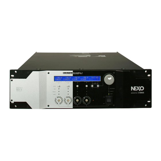
- Page 1 NXAMP4X1 & NXAMP4X4 Powered TDcontrollers User Manual v1.7 (LOAD2_52)
-
Page 3: Fcc Information (U.s.a.)
FCC INFORMATION (U.S.A.) 1. IMPORTANT NOTICE: DO NOT MODIFY THIS UNIT! Compliance with FCC regulations does not guarantee that interference will not This product, when installed as indicated in the instructions contained in this occur in all installations. If this product is found to be the source of interference, manual, meets FCC requirements. -
Page 4: Power Supply/Power Cord
Water warning Power supply/Power cord • Do not expose the device to rain, use it near water or in damp or wet conditions, or • Only use the voltage specified as correct for the device. The required voltage is place containers on it containing liquids which might spill into any openings. printed on the name plate of the device. -
Page 5: Important Notice For The United Kingdom
XLR-type connectors are wired as follows (IEC60268 standard): pin 1: ground, pin 2: hot (+), and pin 3: cold (-). Use only Neutrik NL4 plugs for connecting Speakon connectors. NEXO-SA cannot be held responsible for damage caused by improper use or modifications to the device or data that is lost or destroyed. •... -
Page 6: Table Of Contents
TABLE OF CONTENT TABLE OF CONTENT FCC INFORMATION (U.S.A.) ............................3 IMPORTANT SAFETY INSTRUCTIONS......................... 3 PRECAUTIONS..................................3 ..............................4 OWER SUPPLY OWER CORD .................................... 4 O NOT OPEN ..................................4 ATER WARNING ............................4 F YOU NOTICE ANY ABNORMALITY ..............................4 OWER SUPPLY OWER CORD .................................... - Page 7 TABLE OF CONTENT (1) P ..................................13 OWER SWITCH (2) A ..............................13 MPLIFIER INDICATORS (3) LCD ..................................14 DISPLAY (4) E ...................................14 NCODER (5) N (A & B)............................14 AVIGATION BUTTONS (6) V ................................14 OLUME INDICATORS (7) M .................................14 UTE BUTTONS (8) S ................................14 ELECT BUTTONS (9) C...
- Page 8 TABLE OF CONTENT (1) ..............................33 ATCHING AND ROUTING & (2) ............................33 ELAY POLARITY INVERSION ................................. 33 ACTORY SET UP DELAY ................................33 SER SET UP DELAY & F ............................... 33 QUALISATION ILTERING (3)............................33 UBSONIC AND FILTERING (3) ....................... 34 QUALISING WIDEBAND ACOUSTICAL RESPONSE EQ (4)..............................
- Page 9 TABLE OF CONTENT (1) E ™ IN P ..............................60 THERSOUND (2) E ™ .........................61 THERSOUND NETWORK TATUS (3) E ™ OUT P ...............................61 THERSOUND (4) R ES100 .................................61 EMOTE PORT ™ ........................61 ARIOUS THERSOUND DEVICES DESCRIPTION ES100 ..........................62 DIRECTIONAL DEVICES ES100 ...........................62 DIRECTIONAL...
- Page 10 TABLE OF CONTENT ..............................79 ELECTING CABINET FAMILY ..............................79 ELECT YOUR CABINET SET TECHNICAL SPECIFICATIONS............................. 80 THERMAL DISSIPATION AND CURRENT DRAWN ....................81 DIMENSIONS ..................................82 APPLICATION NOTE: DRIVING THE SUB FROM THE AUX SEND..............83 MAIN ?............. 83 HAT IS THE PHASE RELATION BETWEEN THE OUTPUT OF YOUR MAIN...
-
Page 11: Nxamp Versus Nx242: What's New
NXAMP VERSUS NX242: WHAT’S NEW? NXAMP versus NX242: What’s new? The NXAMP Powered TDcontroller has been designed in order to provide ascendant compatibility with its predecessor – the NX242 Digital TDcontroller. What’s remaining the same? DSP core The DSP used in the NXAMP are from the same family (same core) than the one used in NX242 and on the NXTENSION board. -
Page 12: Computing Resources
NXAMP VERSUS NX242: WHAT’S NEW? Computing resources The DSP resources have been multiply by 3.5 between the NX242ES4 and the NXAMP (so it means by 7 between the NX242 and the NXAMP). This will ensure that the NXAMP will have enough DSP resources to deal with many years of algorithm improvements. Other key components like CPU speed, memory quantities and so on have been also upgraded. -
Page 13: Quick Start
QUICK START Quick Start This section will allow you to quickly understand the basic functions of this product. If you already know the previous NEXO digital TDcontrollers, such as NX241 or NX242, you may be able to use the NXAMP Powered TDcontroller quickly as it has been designed with a similar user interface. -
Page 14: Lcd Display
QUICK START amplifier to be brought back from Stand-by to power on mode through remote control. The last LED, ‘Amp Protect’ reflects the protection status of the amplifier. If this LED is lit, it signifies that the amplifier is reducing or muting one or several outputs due to malfunctions as overheating, output DC, short circuitry …... -
Page 15: Channel Indicators
QUICK START (9) Channel indicators For each channel, you have three LEDs indicator. The ‘Sense’ LED will light to green when a certain level of current is detected on the output, meaning that a cabinet is connected and that some signal is flowing to it. The ‘Protect’ LED will light to yellow if the TDcontroller is applying a VCEQ protection on that channel (see further for details). -
Page 16: Back Panels Description
QUICK START Back panels description (1) Mains connectors This is the mains input for the NXAMP. There is one mains plug on NXAMP4X1 and two mains plug on NXAMP4X4. • On NXAMP4X1, the plug is a Powercon 20A for the 100 ~ 120 Volts model (ref. NXAMP4X1U) and a standard IEC 3 pin for the 220 Volts model (ref. -
Page 17: Expansion Slot
QUICK START (3) Expansion slot This slot is used for extra audio inputs and remote control. See further in the manual for details about the available options. Since July 2009, all NXAMP4x1s and NXAMP4x4s are shipped with an expansion card fitted in, the NX-DFLT card. -
Page 18: Rear End Mounting Holes
QUICK START (7) Rear end mounting holes If the NXAMP is to be rack mounted and transported frequently, be sure to support the rear end of the unit with mounting hardware that matches the size of the rack used. Basic functions Reset You can reset the unit without powering off by simultaneously depressing buttons A, B &... -
Page 19: Using The Amplifier Without The Tdcontroller Functionality
QUICK START Using the amplifier without the TDcontroller functionality If you want to use the amplifier without the TDcontroller, just choose the “FLAT mode” setup. In this mode, no EQ and no protection is applied to the cabinets. Please note that the amplifier will still have 2.2 ms analog input to analog output latency in that mode (i.e. -
Page 20: What's Inside The Carton Box
WHAT’S INSIDE THE CARTON BOX What’s inside the carton box WARNING ! The shipping weight of the NXAMP4X1 (U or C version) is nearly 21 Kg (46 lb). The shipping weight of the NXAMP4X4 (U or C version) is nearly 30 Kg (66 lb). Because of the large size of the carton box it is recommended to manipulate the box with two persons. -
Page 21: Setting-Up Advice
SETTING-UP ADVICE Setting-Up Advice Earth connection WARNING! THIS APPLIANCE MUST BE EARTHED. The green and yellow wire of the mains cord must always be connected to an installation safety earth or ground. The earth is essential for personal safety as well as the correct installation of the system, and is internally connected to all exposed metal surfaces. -
Page 22: Mounting The Nxamp In A Rack (Grounding, Shielding & Safety Issues)
SETTING-UP ADVICE Mounting the NXAMP in a rack (Grounding, shielding & safety issues) The NXAMP Powered TDcontroller is intended for rack mounting. The only accessible part during use shall be the front panel of the unit. Any space above or under the TDcontroller shall be obstructed with a blank panel. -
Page 23: Using The Nxamp Without A Rack
SETTING-UP ADVICE With NXAMP4X1, because of this layout, it is not possible to use some rack rails with 2 holes per rack unit (see picture bellow), because you will loose ½ U of rack space on the top and bottom of the amplifier. Thus continuous rack rails or with 4 holes per rack unit should be used. -
Page 24: Analogue Input Signal Cables
SETTING-UP ADVICE The immunity (this word describes the ability to cope with electromagnetic disturbance generated by other items and natural phenomena) requirements that we have considered exceed those applicable to the “Commercial and light industrial environment” of the product family EMC standard for immunity. In order to provide a further safety margin, we recommend that you do not operate the Powered TDcontrollers in the presence of electromagnetic interference exceeding half of the limits found in this standard. -
Page 25: Nxamp Power Outputs Wiring
SETTING-UP ADVICE This technique prevents noise currents flowing on the return path of the signal. (Note that this is only acceptable for a short cable). NXAMP power outputs wiring NEXO recommends the exclusive use of multi-conductor cables to connect the system: the cable kit is compatible with all the cabinets, and there is no possible confusion between LF, MF and HF sections. -
Page 26: General Description
GENERAL DESCRIPTION GENERAL DESCRIPTION Global architecture NXAMP4X1 Global architecture The diagram bellow shows the global architecture of the NXAMP4X1 amplifier. NXAMP4X4 Global architecture The diagram bellow shows the global architecture of the NXAMP4X4 amplifier. PAGE 26 OF 91... -
Page 27: Power Supply Block
GENERAL DESCRIPTION Power Supply Block Power Supply is certainly the most important part of an amplifier. Most of the time, the Power supply is limiting the power of an amplifier, more than the amplifying circuit itself. • On NXAMP4X1, two large power supplies are used, one for channel (1 and 2) and the other for channel (3 and 4). -
Page 28: Analog Input Block
GENERAL DESCRIPTION design ensures high efficiency and low noise. Moreover, because the two converters work in opposite phase, some noise is cancelled; this is preferable for both sound quality and EMC (Electro magnetic compatibility). Analog Input block After linking the two XLRs for each channel, the analog input block has an EMC filter and a precision input buffer that will remove the common noise on the input signal. -
Page 29: Power Amplifier Blocks
On the pure amplification side, it utilizes custom transistor (thin chip and small thermal resistance), and the well known Yamaha EEEngine technology, that offers the sonic quality of the conventional class AB amplifier with the efficiency of the class D. -
Page 30: User Interface Block
GENERAL DESCRIPTION You can see with the gray line on the above drawing that unused pins on output speakon are shorted together, but are not connected to ground. Therefore be careful as very high voltage might be present on these unused pins. User interface block The user interface block has already been described through the front panel description in the first part of this document. -
Page 31: Expansion Slot Block
ES monitor by Auvitran application, and 4 channels of 24 bits 48 KHz audio). NEXO expansion slot form factor is not compatible with the Yamaha mini-YGDAI form factor. Thus, Yamaha mini-YGDAI card cannot be fitted inside NXAMP Powered TDcontroller. -
Page 32: Block Diagram Description
BLOCK DIAGRAM DESCRIPTION Block diagram description The block diagram bellow shows the global signal path inside the DSPs, for one channel (identical for all the channels): The detail of each block numbered is given bellow. PAGE 32 OF 91... -
Page 33: Patching And Routing (1)
BLOCK DIAGRAM DESCRIPTION Patching and routing (1) Basically, any combination of the four XLR analog inputs (numbered A to D on the back panel) can be patched to each channel of the amplifier. If an expansion board is fitted, the four added digital input (numbered A to D also) can be mixed as well. -
Page 34: Equalising Wideband Acoustical Response (3)
BLOCK DIAGRAM DESCRIPTION The high pass filters are also extremely important as they optimise excursion at very low frequency which is a very important safety factor. (Therefore do not use set-ups which are not designed for the cabinet you are using). Equalising wideband acoustical response (3) This wideband equaliser section achieves the correction required to obtain a flat system response, as the cabinets are acoustically designed for maximum efficiency on the whole... -
Page 35: Protections
BLOCK DIAGRAM DESCRIPTION The NXAMP TDcontroller will limit the user gain adjustment to a group of channel in specific case such as cardioids setups (for example on CD18 setup, gain is linked between front and rear loudspeaker). Protections Each channel has its own simulation and protection process. Each audio channel contains a combination of controlled gain stages (let's call them VCA’s as in our analogue circuitry). -
Page 36: Hf Displacement Control (12)
BLOCK DIAGRAM DESCRIPTION particular area (this is block (10)). As with displacement VCEQ, another set of mechanical stress VCEQ is needed for band-pass cabinets (this is block (11)). HF displacement control (12) In case of passive setups, a channel will deal with several loudspeakers after passing through the passive filter of the cabinet. -
Page 37: Interchannel Regulation (19)
BLOCK DIAGRAM DESCRIPTION The so-called Physiologic Dynamic Control (see block diagram) is intended to avoid unwanted effects as a result of a too long attack time constant. By anticipating the operation of the temperature limiter, it prevents a high level Audio signal appearing suddenly then being kept up for a period, which is long enough to trigger the temperature limiter. -
Page 38: Menu Description
MENU DESCRIPTION MENU DESCRIPTION The diagram bellow shows the internal structure of the menus accessible by the user from the front panel. Follow the arrow corresponding to the “A” or “B” button for each menu to enter the next one. NXAMP Startup Nothing pressed A+B pressed... -
Page 39: Adjusting Volume
MENU DESCRIPTION Repressing A & B buttons while the NXAMP is starting (this last 2 seconds). At the end of the boot time, the above screen should appear, while the amplifier part itself starts up (this last around 18 seconds, and ends when you hear the output relays moving and see the “Amp Protect”... -
Page 40: Adjusting Delay
MENU DESCRIPTION The volume setting for each channel can always be clearly seen from the front panel surrounding LED (white/blue) around each mute button. The position of the LED gives the value of the volume, like it would be for a traditional analog volume pot. The picture bellow gives the attenuation value for each LED. -
Page 41: Adjusting Gain
MENU DESCRIPTION corresponding “select” button. The channel name on screen will then be put between bracket (see on the picture above, channel 2 is selected). Then turn the wheel to change the delay setting (maximum delay is 66.6 meters). You can select multiple channels by pressing several “select” buttons at the same time. When a selected channel reaches the maximum value, it will cease to increase by continuing to turn the wheel, but other selected channels may still increase the setting: be careful not to change a gap between two channel settings when selecting multiple channels... -
Page 42: Adjusting Array Eq
MENU DESCRIPTION Adjusting Array EQ The Array EQ of each channel can be adjusted from the Array EQ menu. Bellow is a picture of this menu. The Array EQ value can be read on the top of the LCD screen for each channel (unit is dB). To change the Array EQ for a given channel, select the channel first by pressing the corresponding “select”... -
Page 43: Headroom Concept
MENU DESCRIPTION bracket (see on the picture above, channel 2 is selected). Then turn the wheel to change the headroom setting (from – 12 dB to 0 dB). You can select multiple channels by pressing several “select” buttons at the same time. When a selected channel reaches the maximum value, it will cease to increase by continuing to turn the wheel, but other selected channels may still increase the setting: be careful not to change a gap between two channel settings when selecting multiple channels... -
Page 44: Options Menu
MENU DESCRIPTION In the same time, the output (analog or digital) gains of all the channels are automatically adjusted to keep the same overall gain from inputs to outputs of the NXAMP. Advantage of reducing the headroom is that it adapts the resolution of the converters to the scale of the analog input signal, thus improving background noise and reducing distortion. -
Page 45: System Config
MENU DESCRIPTION System config This menu allows changing between several speaker setups inside a same family or even through any family, even if this last solution is not recommended. Same family means that same cabinet are connected to same outputs of the amplifier. Mainly this menu is for comparing quickly to setup (Wideband and Crossover for example) without restarting the amplifier. -
Page 46: Input Patch
MENU DESCRIPTION Input Patch By default and depending on the selected speaker setup selected, some or all of the four inputs will be patched to the outputs. For example, 4 independent channels setups (like 4 x PS15) will use each analog input patched to each output, but 4 way active setups (like Alpha) will use only one analog input patched to all the outputs. - Page 47 MENU DESCRIPTION Now that one of the channels is selected, you can see the inputs available on the top line of the screen. Bellow screen is if analog inputs have been selected in the previous menu. On the back of the amplifier, you can see Analog Input A, Analog Input B, and so on. These inputs are named “XLR_A”...
-
Page 48: Save/Recall User Setups
MENU DESCRIPTION You can toggle the status of the input which is blinking by depressing the “B” button. If the brackets appear around this input, the patch is ON, if it is clear, then the patch is OFF. You can go from one input to the other by turning the wheel. Note: Of course several inputs can be patched to one output. - Page 49 MENU DESCRIPTION Once the button “Save” has been pressed, you will be requested to enter the name for that user setup (default name is USERSET followed by the setup number). Starting from the first character, turn the wheel to choose a letter, and then depress the “select 4” (for “Next”) button to go to the next letter.
-
Page 50: Security
MENU DESCRIPTION Once the button “Recall” has been pressed, a confirmation step is added. Choose “Yes” to go on with recalling (this is button “Select 4”), or “No” to go back to the previous screen. If the selected user setup is recalling a different speaker setup that the one currently in use, another confirmation message will be displayed. - Page 51 MENU DESCRIPTION When the remote controls are LOCKED, the user can monitor the unit but cannot change settings through the network. However, the MUTE buttons are still working. This feature is enabled through the same password. When this menu is entered, the following display will appear: Local : FREE Remote :...
-
Page 52: Gpio Mode
MENU DESCRIPTION GPIO Mode This menu allows choosing the way the GPIO are handled by the NXAMP Powered TDcontroller. There are currently 5 modes of GPIO which are described bellow. To change the current GPIO mode, press Edit (“Select 4” button) and turn the wheel up or down to the selected GPIO mode. - Page 53 MENU DESCRIPTION If GPInput1 is High, Channel 1 will be muted. If GPInput1 is Low, Channel 1 will be unmuted. Front Panel mute/Unmute is still working. If GPInput2 is High, Channel 2 will be muted. If GPInput2 is Low, Channel 2 will be unmuted.
- Page 54 This mode is intended to be used with momentary "High" signals (like push buttons). It is recommended to use the Yamaha CP4SW remote control panel for DME. Connect the button 1 to 4 to the GPI 1 to 4, and each LED to GPO 1 to 4. Here is the detail:...
- Page 55 This mode is intended to be used with momentary "High" signals (like push buttons). It is recommended to use the Yamaha CP4SW remote control panel for DME. Connect the button 1 to 4 to the GPI 1 to 4, and each LED to GPO 1 to 4. Here is the detail:...
-
Page 56: Miscellaneous Options
MENU DESCRIPTION GPOutput1 is ON when setup 1 has been recalled. GPOutput2 is ON when setup 2 has been recalled. GPOutput3 is ON when setup 3 has been recalled. GPOutput4 is ON when setup 4 has been recalled. GPOutput5 reflects the GPInput1 (with a small delay and without glitches). GPOutput6 reflects the GPInput2 (with a small delay and without glitches). -
Page 57: Installation Recommendations
INSTALLATION RECOMMENDATIONS Installation Recommendations Audio Chain Recommendations About « Loudspeaker Management Devices » The NXAMP’s factory delay presets are optimised to provide the best possible crossover between the MAIN SYSTEM and SUB systems. Optimum results are always obtained for strictly identical signals feeding simultaneously all the NEXO NXAMP Digital TDcontrollers. -
Page 58: Geometrical Alignment
INSTALLATION RECOMMENDATIONS We recommend that the system is adjusted so that arrivals from MAIN SYSTEM array and SUB speakers are coincident at a fairly distant listening position (typically further than the mixing position). Geometrical alignment In the example below, r being the smaller distance from MAIN SYSTEM array to listener position, and r being the smaller distance from SUB to listener position, the distance... - Page 59 INSTALLATION RECOMMENDATIONS If the MAIN SYSTEM phase reading appears to be superior to the SUB phase reading, then MAIN SYSTEM will have to be delayed with a value close to the one given by the geometrical alignment. If SUB appears to be in advance to MAIN SYSTEM, then SUB will have to be delayed with a value close to the one given by the geometrical alignment.
-
Page 60: Nxes104 Expansion Board And Remote Control
The NXES104 is designed to fit the NEXO’s slot form factor that can be located on the back panel of the NXAMP Powered TDcontrollers. NB: This slot features an 80-pins internal connector that is not compatible with the Yamaha mini-YGDAI slot. -
Page 61: Ethersound Network Status Leds
NXES104 EXPANSION BOARD AND REMOTE CONTROL ™ (2) Ethersound network Status LEDs These four LEDs reflect the status of the Ethersound™ links. The two LEDs next to the IN port shows that data is received from the IN port (when the top one, marked “Rx” blinks) or are send through the IN port (when the bottom one, marked “Tx”... -
Page 62: Mono-Directional, Non Es100 Devices
NXES104 EXPANSION BOARD AND REMOTE CONTROL Mono-directional, non ES100 devices Simplest Ethersound™ devices are mono-directional, non ES100: These devices features two ports (ES IN and ES OUT) and can be only connected to mono-directional networks (64 channels of 24bits/48 KHz). Do not use them in a bidirectional part of an Ethersound network or in a network where ES100 functions are used. -
Page 63: Ethernet Additional Hardware
NXES104 EXPANSION BOARD AND REMOTE CONTROL Ethernet Additional hardware Hubs A hub (also known as repeater) is a central connection point for computers on a star- topology-based network. Any data it receives is broadcasted to all ports, and then only the computer that is ‘listening’... -
Page 64: Ethernet Cables
NXES104 EXPANSION BOARD AND REMOTE CONTROL Ethernet cables Cables used within the EtherSound network are straight cables. The cable used to connect directly the remote control PC to the Primary Master or to any of the “Remote ES100 port” is a crossover cable. The following paragraphs describe the main twisted pair cable types used. - Page 65 NXES104 EXPANSION BOARD AND REMOTE CONTROL WARNING! Do not use FTP cabling for live application. STP stands for Shielded Twisted Pair: Screen is made of copper braid. SFTP stands for Overall Braid + Foil Shielded Twisted Pair: Foil screen and braid shield. For all these cables, transmission characteristics are the same.
-
Page 66: Fiber Optic
NXES104 EXPANSION BOARD AND REMOTE CONTROL Fiber Optic Fiber Optic is similar to twisted pair but does not conduct electricity. It is used in situations where a network may suffer from environmental conditions (e.g. lightning), such as in LAN connections between buildings. Fiber optic is also very valuable where electronic emissions or electro-magnetic interferences may have an impact on the network, e.g. -
Page 67: Compatibility Issues
NXES104 EXPANSION BOARD AND REMOTE CONTROL NEXO provides in each revision of the NXAMP firmware the last version of the ESmonitor software that has been successfully tested with this firmware. It is recommended to use this specific version of the ESmonitor software. Please refer to the ESmonitor User Manual provided by Auvitran as a pdf file when installing the ESmonitor application on your computer. -
Page 68: Virtual Front Panel
NXES104 EXPANSION BOARD AND REMOTE CONTROL Here is now the full control page when using ESmonitor v3.8 or above and LOAD2_52. (1) Virtual front panel This virtual front panel is a copy of the NXAMP user interface. You can see the LCD display and the front panel LEDs status. -
Page 69: Standby Button
NXES104 EXPANSION BOARD AND REMOTE CONTROL (3) Standby button Pressing this button will put the NXAMP in standby mode: the large power supplies used by the power amplifiers are turned off, and the controller is put in a low power mode. Once in standby, the control page of the NXAMP in ESmonitor will become gray and all the controls are non working. -
Page 70: Input Patch
NXES104 EXPANSION BOARD AND REMOTE CONTROL Select the group you wish to put the NXAMP in. You can group NXAMP4x1 and NXAMP4x4 into the same group. One NXAMP can be part of several groups (for example you can do a group with all units, and some smaller ones for specific applications). -
Page 71: Output Meters
NXES104 EXPANSION BOARD AND REMOTE CONTROL (8) Output meters For each channel there are two output meters; the left one is showing the output voltage (V), whether the right one is showing the output current (A). (9) Mute button Click on this button to mute or unmute individually a channel. (10) Volume control This button can set up the volume for each channel of the NXAMP. -
Page 72: Overmute
NXES104 EXPANSION BOARD AND REMOTE CONTROL error will be displayed here. If the unit is in standby, it will be also shown here. (16) Overmute The “Mute all” button acts as an “Overmute” button: When pressed, the four channels of the unit will be muted, but the individual mute status of each channel is preserved. -
Page 73: Notes
NXES104 EXPANSION BOARD AND REMOTE CONTROL (17) Notes In this textbox you can take some notes of your choice. The text is saved on the computer, not on the NXAMP itself. (18) Location This textbox is foreseen to enter the physical location of the unit. The text is saved on the computer not on the NXAMP itself. -
Page 74: Cabinet Setup
NXES104 EXPANSION BOARD AND REMOTE CONTROL (22) Cabinet Setup Pressing the “Set” button in this control displays the list of the setups available into the memory of the NXAMP. By default only the setup from the same family are displayed. NB: First time you press the “Set”... -
Page 75: Nxwin4 Software For Nxamp Firmware Upgrade
NXWIN4 SOFTWARE FOR NXAMP FIRMWARE UPGRADE NXwin4 software for NXAMP firmware upgrade Please check regularly on NEXO website (www.nexo-sa.com) for NXAMP Powered TDcontroller firmware upgrade. These upgrades are freely downloadable and can improve: • NEXO’s setup for cabinets (including new setups for new products). •... -
Page 76: Ethersound™ Upgrade
NXWIN4 SOFTWARE FOR NXAMP FIRMWARE UPGRADE Ethersound™ upgrade To upgrade from the Ethersound™ port you will need: • A computer running Windows XP with NXwin4 installed • A RJ-45 Ethernet 100 base TX full duplex port • A crossover cat5 network cable. Connect the computer to the NXAMP Locate the serial port or the one of the usable Ethersound™... - Page 77 NXWIN4 SOFTWARE FOR NXAMP FIRMWARE UPGRADE NB: Even if you plan to use the serial port for upgrade, your computer must have an Ethernet port for the software to set up correctly. Then through the start menu, double-click on Programs> Nexo> Firmware Update> NXwin4.
-
Page 78: Put The Nxamp In Download Mode
NXWIN4 SOFTWARE FOR NXAMP FIRMWARE UPGRADE Put the NXAMP in download mode That means power the unit “ON” while having the ‘mute 1’ button down. (1) Hold the mute 1 button down, and keep it down. (2) Turn ON the NXAMP Powered TDcontroller. The NXAMP screen will display the revision of the boot loader, and then the following message will appear: Begin the upgrade... -
Page 79: Using The Controller After A Firmware Update
NXWIN4 SOFTWARE FOR NXAMP FIRMWARE UPGRADE At the end of the download the NXAMP will start up normally, displaying the new firmware revision. Using the controller after a firmware update Choosing a cabinet setup After the download of a new firmware, the NXAMP powered TDcontroller will be by default in FLAT mode, it means that the audio flows from the inputs to the outputs without treatment. -
Page 80: Technical Specifications
TECHNICAL SPECIFICATIONS TECHNICAL SPECIFICATIONS POWER SPECIFICATIONS FOR NXAMP Powered TDcontroller Number of channels 4 channels, 3 channels (2 non bridged + 1 bridged) or 2 channels (2 bridged) NXAMP4X1 NXAMP4X4 Max. output power (8 Ω) 600 W (non bridged) 1900 W (non bridged) 1800 W (2 channels bridged) 6600 W (2 channels bridged) Max. -
Page 81: Thermal Dissipation And Current Drawn
THERMAL DISSIPATION AND CURRENT DRAWN Thermal dissipation and current drawn Test signal: Pink Noise, bandwidth limited 22Hz to 22 kHz. All channels driven. Thermal Line Current (A) Watts Dissipation NXAMP4X1 Dissipated 120V 230V Btu/h kcal/h Idle 8ohms/ch 11.1 1337 1/8out 4ohms/ch 16.7 2023... -
Page 82: Dimensions
DIMENSIONS Dimensions NXAMP4X1 front view dimensions NXAMP4X4 front view dimensions NXAMP4X1 and NXAMP4X4 top view dimensions PAGE 82 OF 91... -
Page 83: Application Note: Driving The Sub From The Aux Send
APPLICATION NOTE: DRIVING THE SUB FROM THE AUX SEND Application Note: Driving the Sub from the AUX send It is quite common to use the AUX send of a mixing desk to drive the Sub section of a PA system. This gives the mixing engineer more flexibility to set the level of its subbass relative to the main PA, apply special effects, use a different EQ on the Sub…However, it also rises some serious issues for the performance &... -
Page 84: Precautions & Check
APPLICATION NOTE: DRIVING THE SUB FROM THE AUX SEND Consider the simple example of the AUX signal passing through a digital device (without processing) that is adding a delay of 2ms due to its conversion time. The AUX is then sent to a CD12 sub while the MAIN is send to the S850 rig. - Page 85 APPLICATION NOTE: DRIVING THE SUB FROM THE AUX SEND Never add additional low pass filtering on the SUB. (Or high pass to the main system) Inverting polarity on one channel should always result in a massive difference near the crossover point. If the sound is more or less the same the system is no longer aligned. PAGE 85 OF 91...
-
Page 86: Appendix A: List Of Supported Presets (Load2_52)
APPENDIX A: LIST OF SUPPORTED PRESETS (LOAD2_52) Appendix A: List of Supported presets (LOAD2_52) Please see the LOAD2_52_setups.pdf included in the documentation to see a complete list of presets supported in LOAD 2_52 by the NXAMP. Please refer to the documentation enclosed with the firmware if the one loaded in your NXAMP is not LOAD 2_52. -
Page 87: Appendix B: How Is Measured The Amplifier Power
APPENDIX B: HOW IS MEASURED THE AMPLIFIER POWER? Appendix B: How is measured the amplifier power? This part of the document describes the setup we have used to measure the power available on the NXAMP Powered TDcontroller outputs for each load (8, 4 and 2 Ohms). General description of the setup The drawing bellow shows the setup used to measure the output power: Audio Generator... -
Page 88: Precision Of The Measurement
APPENDIX B: HOW IS MEASURED THE AMPLIFIER POWER? measure directly the output voltage on the screen. Precision of the measurement • All the measurement tools (Digital scope and distortion analyzer) have been recently calibrated (less than one year). • We’ve made some measurements on some batch of NXAMP to have a clear idea of the precision of the amplifier itself, from one unit to the other (small differences in the manufacturing of the custom transformer of the larges power supplies are the main factor for having different power capability). -
Page 89: Usable Mains Cord In Europe
USABLE MAINS CORD IN EUROPE Usable mains cord in Europe The SEMKO (CE) certification in Europe is based on the assumption that the user will use one of the following mains cord to use NXAMP4X4 or NXAMP4X1. Please choose one from the list bellow. -
Page 90: Rohs Certificate
ROHS CERTIFICATE ROHS certificate PAGE 90 OF 91... -
Page 91: User Notes
USER NOTES User Notes Nexo S.A. Parc d’Activité de la Dame Jeanne F-60128 PLAILLY Tel: +33 3 44 99 00 70 Fax: +33 3 44 99 00 30 E-mail: info@nexo.fr www.nexo-sa.com PAGE 91 OF 91...