Table of Contents
Advertisement
Quick Links
Advertisement
Table of Contents

Related Manuals for Panasonic AJ-PD500P


Summary of Contents for Panasonic AJ-PD500P
-
Page 1: Operating Instructions
Register now!! Operating Instructions Memory Card Recorder Before operating this product, please read the instructions carefully and save this manual for future use. • AVCHD capability is available when the optional AVCHD Codec board AJ-YCX500G is installed. ENGLISH M1013KT0 -PS VQT5C69A(E) -
Page 2: Read This First! (For Aj-Pd500P)
Operation at a voltage other than 120 V AC may grounding of the power outlet, please consult a require the use of a different AC plug. Please qualified electrician. contact either a local or foreign Panasonic authorized service center for assistance in selecting WARNING: an alternate AC plug. -
Page 3: Important Safety Instructions
Read this first! (For AJ-PD500P) (continued) IMPORTANT SAFETY INSTRUCTIONS 1) Read these instructions. 2) Keep these instructions. 3) Heed all warnings. 4) Follow all instructions. 5) Do not use this apparatus near water. 6) Clean only with dry cloth. 7) Do not block any ventilation openings. Install in accordance with the manufacturer’s instructions. - Page 4 Read this first! (For AJ-PD500P) (continued) FCC NOTICE (U.S.A.) Declaration of Conformity Model Number: AJ-PD500P Trade Name: Panasonic Responsible Party: Panasonic Corporation of North America Two Riverfront Plaza, Newark, NJ 07102 Support contact: 1-800-524-1448 This device complies with part 15 of the FCC Rules.
-
Page 5: Read This First! (For Aj-Pd500E)
Read this first! (For AJ-PD500E) WARNING: CAUTION: This equipment must be earthed. To reduce the risk of fire or electric shock, refer To ensure safe operation, the three-pin plug must mounting of the optional interface boards to be inserted only into a standard three-pin power qualified service personnel. - Page 6 Stand-by mode. EEE Yönetmeliğine Uygundur. EEE Complies with Directive of Turkey. Manufactured by: Panasonic Corporation, Osaka, Japan Importer’s name and address of pursuant to EU rules: Panasonic Testing Centre Panasonic Marketing Europe GmbH...
- Page 7 Read this first! (For AJ-PD500E) (continued) EMC NOTICE FOR THE PURCHASER/USER OF THE APPARATUS 1. Applicable standards and operating environment (AJ-PD500E) The apparatus is compliant with: • standards EN55103-1 and EN55103-2, and • electromagnetic environments E1, E2, E3 and E4 2.
- Page 8 • Playing AVC video that was obtained from a licensed provider. For details, refer to the MPEG LA, LLC website (http://www.mpegla.com). Website URL http://pro-av.panasonic.net/ About copyrights • Copyright laws may prohibit use, except for personal pleasure, of your recorded video and audio content without permission...
-
Page 9: Table Of Contents
Contents Read this first! (For AJ-PD500P) ..... 2 Deleting Clips on the FTP Server ......60 Viewing FTP Server Clip Information ......60 Transferring Clips ............. 60 Read this first! (For AJ-PD500E) ..... 5 Transferring SD Memory Card Data ......62 Usage Precautions .........10... -
Page 10: Usage Precautions
Furthermore, please also When carrying the unit, be careful not to drop it. note that Panasonic is not liable to pay compensation for any • A strong impact may damage the unit and result in it be- damages arising from the use of this function. - Page 11 Details about user registration and the extended warranty: Please note, this is a site that is not maintained by Panasonic Canada Inc. The Panasonic Canada Inc. privacy policy does not apply and is not applicable in relation to any information submitted. This link is provided to you for convenience.
-
Page 12: Before Use
Before use, download the necessary drivers from the Panasonic website and install them on the personal computer. For the installation procedure, refer to installation manual on the Panasonic website. For the latest information on drivers, refer to the Panasonic website. Refer to (➝ “Website URL” page 8) Usage Precautions: Before Use... -
Page 13: Accessories And Options
Accessories and Options Accessories AC power cord CD-ROM • AJ-PD500P • AJ-PD500E (For the U.K.) (For areas other than the U.K.) • Operating instructions • After unpacking, dispose of the AC power cord caps and packing materials properly. Options • AVCHD codec board (AJ-YCX500G) Note: •... -
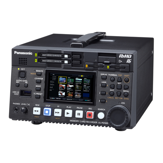
Page 14: Control Reference Guide
Control Reference Guide Controls 2 3 4 20 7 9 8 18 11 19 10 About button labels: Orange labels indicate alternate functions enabled by simultaneously pressing the [SHIFT] button. <Example> Press the [SHIFT] and [REMOTE/MODE] buttons simultaneously to execute the [MODE] button function. REMOTE, MODE button... - Page 15 Cursor control buttons PAUSE button Up/down/left/right cursor buttons: Press this button during playback to pause (STILL) play- • These buttons control the cursor movement for thumb- back to display a still image. nails, menus, etc. Press the button while playback is paused to resume play- •...
-
Page 16: Slots And Other Parts
Slots and Other Parts 3 2 6 lamp P2 memory card access lamps (➝ “How to Turn On/Off the Power” page 20) (➝ “P2 Card Access Lamp and P2 Card Status” page 22) button P2 memory card slots This button turns the power on or off. (➝... -
Page 17: I/O Connectors
I/O Connectors 14 15 10 9 TIME CODE IN/OUT Jacks REF IN jacks These jacks are for inputting HD and SD reference video TIME CODE IN: This jack is for recording an exter- signals. nal time code onto a P2 card. Note: TIME CODE OUT: This jack is for outputting the play-... - Page 18 HDMI OUT port DC IN connector Connect a monitor or TV using an HDMI cable. Connect a 12 V DC power supply. When the voltage drops to approximately 10.6 V, the unit Note: is shutdown automatically. (When the “EXT DC IN SE- •...
- Page 19 PARALLEL REMOTE connector This is a 15-pin parallel remote connector. The assignment for each port can be selected in the “PAR- ALLEL PORT PORT1-7 PORT 9-14” (➝ page 100 and page 101) menu item. Port Name Function PORT1 Command input port 1 PORT2 Command input port 2 PORT3...
-
Page 20: Preparation
Preparation How to Turn On/Off the Power Turning On the Power From the power-off state, press the [ ] button to turn on the power. After startup, the lamp lights green. ] button lamp Note: The following messages appear during startup. •... -
Page 21: Setting The Year, Month, Day, And Time
Setting the Year, Month, Day, and Time Set the clock before using the unit the first time. Time zone Time Time Area Area Press the [ ] button on the unit to turn on the difference difference power. 00:00 Greenwich +01:00 Central Europe -00:30... -
Page 22: P2 Cards
P2 Cards P2 Card Access Lamp and P2 Card Status P2 Card Access Lamp P2 Card Status Lights green Recording possible Both writing and reading are possible. Lights orange Recording target Writing and reading are enabled and currently recording target. Flashing orange Card being accessed Writing or reading is in progress. - Page 23 P2 card recording times (Example of using one 64 GB card) “LINE&FREQ” setting (recording format) “REC FORMAT” setting (codec) Recording duration 1080-59.94P, 1080-50P AVC-I100 Approx. 32 minutes AVC-G25 Approx. 110 minutes 1080-59.94i, 1080-50i AVC-I100 Approx. 64 minutes AVC-G25 Approx. 220 minutes 480-59.94i, 576-50i DVCPRO50 Approx.
-
Page 24: Handling Of Recording Data
Handling of Recording Data P2 memory cards and microP2 memory cards are semiconductor memory cards designed for the P2 series, Panasonic’s line of professional video and broadcast equipment. Recording data in the P2 format is ideally suited for com- Drive:\ puter processing because it is a file format. -
Page 25: Using Sd/Sdhc/Sdxc Memory Cards
SD: 8 MB to 2 GB SDHC: 4 GB to 32 GB SDXC: Over 32 GB Use of Panasonic SD, SDHC, and SDXC memory cards and miniSD, miniSDHC, microSD, microSDHC, and microSDXC cards is recommended. Note: When using the AVCHD option, also check “AVCHD Playback Mode” (➝ page 65). -
Page 26: Available Modes
Available Modes This unit comes with three modes: Main mode, USB device mode, and AVCHD playback mode. You can select or change the mode by selecting one of the menu items displayed when you press the MODE button. Main mode has a thumbnail screen for displaying and managing clip thumbnails and playing clips and a recording/playback screen for recording and playback. -
Page 27: Main Mode
Main Mode Recording/Playback Screen Use the recording/playback screen for the following. Adjusting the recording audio levels • Recording to P2 cards Follow the procedure below to change the volume level for re- • Playing back all cards in the order they were recorded cording. - Page 28 Canceling loop recording mode Various types of recording • Select “NORMAL” in the “RECORDING” menu item. AUTO REC Hot swap recording When a camera compatible with the function is connected via When P2 cards are inserted into both of the two P2 memory HD SDI, starting and stopping recording on the unit can be card slots or microP2 memory card slots specified in the automatically controlled using the REC START / STOP func-...
- Page 29 Proxy recording Simultaneously record video as well as time-code data and other real-time data in MPEG4 format or H.264 format to a P2 card or SD memory card separately from the main video and audio material recorded with the unit. (➝...
-
Page 30: Playing Back Clips
Note: Playing Back Clips • The setting values do not change when you turn off the pow- • If you press the multi control dial during the changing of the Playback volume levels, the default values are restored. Before you start playback, set the playback frequency, for- Variable speed playback mat, and other settings in the menu. -
Page 31: Repeat Playback
Frame-by-frame playback Repeat playback Play back playable clips repeatedly. Press [MENU]. Set the “REPEAT PLAY” (➝ page 86) menu item to “ON.” Close the menu. Press the [PLAY] button to start playback. All clips are played repeatedly. • Repeat playback continues until the [STOP] button is pressed. -
Page 32: Thumbnail Screen
Thumbnail Screen This unit has a thumbnail screen for managing clips. A “clip” consists of a set of video, audio, and additional information such as metadata, and a “shot” is a clip generated by a single normal start-to-stop recording operation. A shot that spans multiple P2 cards is handled as one clip. -
Page 33: Names And Functions Of The Parts Of The Thumbnail Screen
Names and Functions of the Parts of the Thumbnail Screen 10111213 Display status Duration The following information is displayed on the screen. Indicates the length (duration) of the clip at the cursor po- sition and the rough current playback position in relation to ALL: All clips the length of the clip. - Page 34 Proxy indicator P2 card slot and storage device or LAN status indi- Indicates that proxy data has been additionally recorded cation for the clip. Indicates the P2 card and storage device or LAN connec- tion status as shown below. Text memo indicator Indicates that text memo data has been added to the clip.
-
Page 35: Changing The Thumbnail Display
Status message Setting the thumbnails to display Displays a message indicating the processing status. For example, the “UPDATING” text message and a rotating Use the cursor buttons to align the cursor with the icon are displayed during screen updating. type of clips you want to display in the “REPOSI- Simple property indication TION”... -
Page 36: Playing Back Clips
Setting the items to display as properties Playing Back Clips Set the simplified property display items to display on the left side of a thumbnail. Playback Use the cursor buttons to align the cursor with the “PROPERTY DISP.” (➝ page 85) menu item. Press the [SET] button to open the item menu. - Page 37 • Pressing the [STOP] button during clip playback stops playback and redisplays the thumbnail screen. • When playback is stopped, the cursor moves to the clip played prior to stopping. • Video and audio playback may be disrupted between clips in different video formats (1080i, 1080p, etc.) or compres- sion formats.
-
Page 38: Selecting And Deselecting Clips
Selecting and Deselecting Clips Adding Text Memos and Shot Marks Select the clips you want to process on the thumbnail screen. A text memo can be added to a clip to mark a specific location of the clip. You can also add a shot mark to a clip to distin- guish it from other clips. -
Page 39: Copying Clips
After pressing the [SET] button to select the thumb- Align the cursor with the copy destination in the list of nail for which you want to delete the text memo, the “COPY” (➝ page 83) menu item and press the press the [SET] button in the “DELETE”... -
Page 40: Deleting Clips
Deleting Clips Repairing and Reconnecting Clips Use the following procedure to delete unnecessary clips from Repairing bad clips a P2 card. The bad indicator (yellow ) is displayed for any clip with a prob- Select the clip to delete. lem caused by, for example, a sudden power outage during re- cording. -
Page 41: Viewing And Editing The Clip Information
View the clip metadata if necessary. Viewing and Editing the Clip Informa- tion Viewing the clip metadata information The detailed information of a clip can be displayed and checked on a screen. Use the cursor buttons to align the cursor with the tar- Use the cursor buttons to align the cursor with a metadata get clip. -
Page 42: Changing Thumbnails
PROXY: Detailed information on proxy data Note: (Format, video codec, video frame • To delete the latitude and longitude, enter a blank space for rate, video bit rate, video resolution, the altitude. They cannot be deleted separately. aspect ratio, TC superimposition on •... -
Page 43: Adding Metadata To Clips During Recording
P2 card that can be item and press the [SET] button. download free of charge from the Panasonic website. For the URL, refer to “Website URL” (➝ page 8). Use the cursor buttons to align the cursor with Install P2 Viewer Plus on a PC and then create a metadata up- “COUNT RESET”... - Page 44 Checking and editing loaded metadata Metadata upload files The settings of the metadata loaded from an SD memory card can be checked. Loading a file Press the [MENU] button and select the “REC META Use the following procedure to load the metadata settings DATA”...
-
Page 45: Formatting P2 Cards And Sd Memory Cards
Formatting P2 Cards and SD Memory Checking the Card Status Cards The P2 card slot status, P2 card usage status, and other card information can be displayed and checked on the screen. Use the cursor buttons to align the cursor with “SLOT n”... -
Page 46: Manual And Automatic Cps Authentication
Write protected mark Manual and Automatic CPS mark is displayed when a P2 card is write pro- Authentication tected. P2 card status When the remaining free space is displayed, the re- maining free space on the P2 card is indicated in the Manual CPS authentication form of a bar meter and as a percentage value. -
Page 47: Connecting An External Device Via The Usb Host Port
The following storage devices can be used. BOpen the thumbnail screen. • Panasonic portable hard disk unit P2 store (AJ-PCS060G) CSelect the “CPS PASSWORD” - “LOAD” (➝ page 82) • Hard disk drives or solid state drives connected via USB 2.0/3.0. - Page 48 Storage device types and available functions The available functions depend on the type of storage device used. The storage device type is displayed below “PARTITION:” on the left side of the EXPLORE screen. (➝ “Viewing storage device information (EXPLORE screen)” page 51) Note: •...
- Page 49 • A storage device is a high-precision instrument whose read and write functions may fail if used in an unsuitable environment. Please note that Panasonic accepts no liability whatsoever for data loss or other damage, either direct or indirect, arising from a storage device failing or for some other reason.
- Page 50 Align the cursor with “YES” in the confirmation mes- Connect a storage device. A storage device that is not in the TYPE S or FAT format will sage and press the [SET] button. be formatted in the TYPE S or FAT format. (➝...
- Page 51 Viewing storage device information Copying clips to a storage device (EXPLORE screen) You can copy just the selected clips rather than the entire card to a storage device. You can display storage device information, select the display of a storage device partition or folder thumbnails, and select a partition or folder as a target for operation (in the EXPLORE Display the thumbnail screen, use the cursor buttons screen).
- Page 52 Partition information Hold down the [SET] button (for at least 1 second). The partition or folder is selected and becomes (for a TYPE S storage device or P2 Store disk) A check mark is displayed for a partition selected as an operation target. NO.: Partition number (1 - ) MODEL:...
- Page 53 Deleting the last partition Clip information The last partition of a storage device can be deleted in the Displays the clip properties. “DELETE LAST PARTITION” (➝ page 84) menu item. Storage device information When TYPE S Note: • Move the cursor to the last partition beforehand. SERIAL: P2 card serial number •...
- Page 54 Viewing clip information • Pressing the [STOP] button during clip playback stops playback and redisplays the thumbnail screen. Various metadata information can be viewed for the clips • When playback is stopped, the cursor moves to the clip stored on a storage device. The information can be displayed played prior to stopping.
- Page 55 Copying to a P2 card by clip Writing back (importing) data from a stor- You can specify a clip on a storage device and copy it to a P2 age device to a P2 card card. Display the thumbnail screen of the storage device. Importing Data from a TYPE S storage device or P2 Store by partition Select a clip to copy.
-
Page 56: Using The Unit Connected To A Network
Using the Unit Connected to a Network The network connector (1000BASE-T/100BASE-TX/10BASE-T) allows you to connect the unit to a network to transfer clips to server devices on the network. (Functions) • The FTP client function enables the unit to send and receive clips Network Settings To use the network functions, set the “NETWORK SEL”... - Page 57 Client settings To transfer clips with the FTP function, you need to set the connection destination and other settings in advance. Set the settings in the “CLIENT SERVICE” (➝ page 95) menu item. CLIENT SERVICE: Item Description Setting value Factory default setting FTP SERVER URL Name or address of connection desti-...
-
Page 58: Using Ftp Client Functions
Note: Using FTP Client Functions There is a delay of a few seconds between the updating of the LAN indicator and the actual status. To use the FTP client functions, you need to set the LAN Folder information settings and FTP client settings in advance. PATH: Path of current folder on FTP server NO.:... -
Page 59: Viewing The Thumbnails Of Clips On An Ftp Server (Ftp Thumbnail Screen)
Operations in the FTP EXPLORE screen Viewing the Thumbnails of Clips on an FTP Server (FTP Thumbnail Right cursor button: Indicates the contents of the subfolder Screen) at the cursor position. Left cursor button: Indicates the contents of the folder at the level above the current folder. -
Page 60: Deleting Clips On The Ftp Server
FTP server/folder information Viewing FTP Server Clip Information URL: URL of connected FTP server USER ID: User ID of logged in user Various metadata information can be viewed for the clips on SSH: Indicates whether SSH is set to ENABLE or DIS- an FTP server. - Page 61 The server screen appears. Writing back from an FTP server (copy) The folders on the set server are displayed. Use the cursor buttons to select the transfer destination folder. Selected clips can be written back from an FTP server on the network to a P2 card or hard disk.
-
Page 62: Transferring Sd Memory Card Data
• Whether an error is generated when the remaining capacity Transferring SD Memory Card Data of the FTP server reaches 0 depends on the FTP server. If an error is not generated, use the procedure above to stop the operation. The data in an SD memory card can be transferred to an FTP •... - Page 63 Writing back from an FTP server (import) A folder selected from an FTP server on the network can be written back to an SD memory card. Display the FTP EXPLORE screen. The folder screen of the FTP server appears. The folders on the set server are displayed. Use the cursor buttons to select the transfer source folder.
-
Page 64: Usb Device Mode
P2 cards inserted in the P2 card slots of this unit as mass storage devices. Note that a separate USB driver, which can be downloaded free of charge from the Panasonic website, needs be installed on the PC.(➝ “Website URL” page 8) -
Page 65: Avchd Playback Mode
• For the latest information not available in the Operating Instruc- card to “LOCK”. tions, visit the support page on the Panasonic website. (➝ “Website URL” page 8) • The unit supports SD memory cards formatted in the FAT12 and... -
Page 66: Operating The Avchd Thumbnail Screen
Displaying the menu Operating the AVCHD Thumbnail Press the [MENU] button when thumbnails are displayed. Screen 2) 3) Switching to AVCHD playback mode Use the following procedure to switch to AVCHD playback mode. Press the [MODE] button. The mode selection menu appears. 4) 5) 6) Thumbnail display status (➝... - Page 67 Various indicators THUMBNAIL MODE: Select the clips to display. : Shot mark Indicates the presence of a shot mark. However, the unit ALL: Displays all clips. cannot record shot marks. SAME Displays the clips in the same playback format. AaA: Resume playback indicator FORMAT: Indicates a clip target for resume playback.
-
Page 68: Card Functions
Select “CLIP PROTECT” and press the [SET] button. CARD STATUS: Displays information on the SD memory card. CLIP PROTECT: USED SPACE: Used space YES: Protects the selected clip. (The mark is dis- FREE SPACE: Free space played.) Select a protected clip to cancel protec- tion. -
Page 69: Setting Playback
Press the [MENU] button to return to the thumbnail Setting Playback screen. Set the playback format and playback method. About clip metadata Setting the playback format The video data recorded on an SD memory card with an AVC- (PB FORMAT) CAM device may include the video and audio formats, shooter name, shooting location, and text memos. -
Page 70: Playing Back Avchd Clips
Resume playback (RESUME PLAY) Playing Back AVCHD Clips Set this to resume playback from where it was last interrupted. Playing and pausing Press the [MENU] button. Clip playback can be performed only from thumbnails. Select “PLAY SETUP” and press the [SET] button. Use the cursor buttons to move the cursor to the clip Select “RESUME PLAY”... - Page 71 AVCHD warning information (when the AJ-YCX500G AVCHD codec board (option) is in- stalled) The following shows the main warnings displayed on the LCD monitor. For details on the other displayed warnings, check the displayed messages. Message Description CANNOT BE USED DUE TO INCOMPATIBLE DATA. Cannot be used because the data standard differs.
- Page 72 Switching clips during the continuous playback of multiple clips Clips may not be able to be switched smoothly during the continuous playback of multiple clips. In AVCHD playback mode, if multiple clips are played back continuously in the following cases, the video may be paused when clips are switched.
-
Page 73: Handling Of Sd Memory Card Recording Data
Handling of SD Memory Card Recording Data Recording data in the AVCHD format is ideally suited for com- puter processing because it is a file format. It includes not only Drive: ¥ video and audio data but also various important information, and has the folder configuration shown on the right. -
Page 74: Screen Display
Screen Display OSD Display The screen display switches between “no display” ➝ “OSD display” ➝ “no display” each time you press the [Display] button. The formats, time codes, and modes are displayed as abbreviations on the playback and recording screens. Note: •... -
Page 75: Deck Information (Diag) Display
Audio level meter display TEXT MEMO display Indicates the input level during recording or recording When the “OSD TC SELECT” (➝ page 96) menu item is set standby and the audio level of the current clip during play- to other than “T&S&M,” a message is displayed when back. -
Page 76: Waveform Monitor (Wfm) Display
Waveform Monitor (WFM) Display This displays a simple waveform monitor on the screen for monitoring video. It can be displayed by setting the “WFM TYPE” (➝ page 96) menu item. WAVE: Waveform display VECTOR: Vector display Note: • Switch the output destination to display in the “OSD OUTPUT” (➝ page 96) menu item. •... -
Page 77: Time Code, User Bits, And Ctl
Time Code, User Bits, and CTL Time code Setting the Time Code and User Bits The time code is used when the time code signal generated Internal mode by the time code generator is to be recorded. The time code values are indicated on the display and in the superimposed display. - Page 78 When you finish setting the start values, press the External mode [SET] button. When the “RUN MODE” (➝ page 88) menu item is set to Press the [STOP] button to switch to stop mode. “FREE RUN,” the time code starts advancing immediately. To cancel this setting, press the [EXIT] button or [CAN- CEL] button.
-
Page 79: Setup Menu
Setup Menu Menu Operations Operate the menu as follows. Press the [SET] button. Note: • A confirmation screen is displayed for some menu items. • Use the cursor buttons to select a process and press the [SET] button. • A check mark is displayed before a set item. •... -
Page 80: Menu Structure
Menu Structure CLIP PROPERTY MENU REPOSITION DELETE FORMAT FORMAT STORAGE COPY EXPORT IMPORT REPAIR RE-CONNECT EXCH. THUMBNAIL EXPLORE AUTHENTICATE CHANGE PARTITION NAME DELETE LAST PARTITION DELETE FOLDER THUMBNAIL SETUP STORAGE COPY SETUP REC/PB REC/PB FUNCTION REC/PB SETUP PROXY SETUP TC/UB/CTL REC META DATA I/F SETUP CLOCK... - Page 81 FILE MENU SETUP DATA (SD CARD) SETUP DATA SELECT SD CARD PROPERTY FORMAT SD CARD LOAD USER DATA INITIALIZE SYSTEM SYSTEM MODE SYSTEM SETUP HOURS METER VERSION Setup Menu: Menu Structure...
-
Page 82: Menu List
Menu List CLIP PROPERTY _ is the factory default setting. Item Settings and brief function description FREQ indications Displays detailed clip information on the screen. Individual items can also be edited. For de- 59.94Hz 50Hz CLIP PROPERTY tails, refer to “Viewing and Editing the Clip Information” (➝ page 41). Displays the card status of the P2 card slots. - Page 83 Item Settings and brief function description FREQ indications After selecting the “FORMAT” menu item, format the P2 card in the P2 card slot to be spec- 59.94Hz 50Hz ified or SD memory card in the SD memory card slot. Note: FORMAT •...
-
Page 84: Thumbnail Setup
Item Settings and brief function description FREQ indications Sets or changes the names of partitions in a storage device. 59.94Hz 50Hz Note: CHANGE • The default value is the date and time when the partition was created. PARTITION NAME • This is enabled only for TYPE S storage devices. •... - Page 85 Item Settings and brief function description FREQ indications Sets the items to display in the simplified property display on the left side of the thumbnails. 59.94Hz 50Hz USER CLIP NAME: Indicates the name of a user clip START TC: Indicates the start time code. REC DATE: Indicates the date of recording.
-
Page 86: Rec/Pb
REC/PB REC/PB FUNCTION _ is the factory default setting. Item Settings and brief function description FREQ indications Selects the recording method. 59.94Hz 50Hz RECORDING NORMAL: Normal recording LOOP: Loop recording Selects whether recording and stopping is performed automatically in accordance with the 59.94Hz 50Hz record and stop signals in the HD SDI... - Page 87 REC/PB SETUP _ is the factory default setting. Item Settings and brief function description FREQ indications Selects the slots for recording. 59.94Hz 50Hz P2: Uses the P2 memory card slots (1 and 2). microP2: Uses the microP2 memory card slots (3 and 4). REC MEDIA Note: Recording is not possible for a slot that is not selected but playback is possible.
- Page 88 PROXY SETUP Note: When other than “NORMAL” is selected in the “REC/PB FUNCTION” - “RECORDING” (➝ page 86) setting menu item, proxy recording cannot be performed even if “REC MEDIA” is set to “P2” or “P2&SD.” _ is the factory default setting. Item Settings and brief function description FREQ indications...
- Page 89 Item Settings and brief function description FREQ indications Sets the time code to use when an external time code is used. 59.94Hz 50Hz EXT LTC: LTC of TIME CODE IN connector. SLTC: LTC information added to the serial signal input to the SDI IN connector. SVITC: VITC information added to the serial signal input to the SDI IN connector.
- Page 90 REC META DATA _ is the factory default setting. Item Settings and brief function description FREQ indications Loads a metadata upload file stored on an SD memory card. LOAD 59.94Hz 50Hz Sets whether to add the loaded metadata during recording. 59.94Hz 50Hz RECORD...
-
Page 91: I/F Setup
I/F SETUP CLOCK For details, refer to “Setting the Year, Month, Day, and Time” (➝ page 21). BASIC _ is the factory default setting. Item Settings and brief function description FREQ indications Sets the ID information to return to the controller. 59.94Hz 50Hz DVCPRO: DVCPRO... - Page 92 Selects the 3G-SDI output format for when “LINE&FREQ” (➝ page 105) is “1080-59.94P” or 59.94Hz 50Hz “1080-50P.” 3G-SDI OUT LEVEL-A: Selects the 3G-SDI LEVEL-A format. LEVEL-B: Selects the 3G-SDI LEVEL-B DL format. This menu is only for the AJ-PD500P Setup Menu: Menu List...
- Page 93 Item Settings and brief function description FREQ indications Selects the aspect ratio for down-conversion output. 59.94Hz 50Hz FIT-V: Changes the ratio to match the input size to the output size along the vertical axis. (The as- pect ratio is maintained.) FIT-H: DOWNCON MODE Changes the ratio to match the input size to the output size along the horizontal axis.
- Page 94 AUDIO _ is the factory default setting. Item Settings and brief function description FREQ indications Selects the audio input signal. 59.94Hz 50Hz SDI: Selects the SDI connector. INPUT SEL ANALOG: Selects the ANALOG AUDIO IN connector. AES/EBU: Selects the AES/EBU connector. INT SG: Selects the internal signal generator.
- Page 95 : -20 dB REF LEVEL FS-18 : -18 dB FS-12: -12 dB This is the factory default setting of the AJ-PD500P. This is the factory default setting of the AJ-PD500E. _ is the factory default setting. Item Settings and brief function description...
- Page 96 Item Settings and brief function description FREQ indications DHCP Automatically sets the network settings by DHCP. 59.94Hz 50Hz ENABLE: Uses DHCP (automatic assignment) DISABLE: Enter the settings without using DHCP (automatic assignment). When “DISABLE” is selected, the following menu items are displayed. Set the items. IP ADDRESS: Sets the IP address.
- Page 97 Item Settings and brief function description FREQ indications Selects the display position for the waveform monitor. 59.94Hz 50Hz RIGHT/TOP: Positioned at top right. LEFT/TOP: Positioned at top left. RIGHT/BOTTOM: Positioned at bottom right. WFM POSI LEFT/BOTTOM: Positioned at bottom left. Note: The display on the LCD monitor moves left or right only.
- Page 98 EXT DC IN _ is the factory default setting. Item Settings and brief function description FREQ indications Sets the remaining level detection type for when an external DC power supply or battery is 59.94Hz 50Hz connected to the DC IN connector. Set NEAR END and END of TYPE A and TYPE B to match EXT DC IN the battery that is to be used.
- Page 99 USER BUTTON You can assign specific functions set in menus to the [USER1] to [USER6] buttons. The settings are stored internally and retained even when the unit is turned off and on. The assigned functions and settings can be confirmed in the DIAG display. _ is the factory default setting.
- Page 100 PARALLEL PORT Registers functions to the input connectors and registers statuses to the output connectors of the PARALLEL REMOTE connec- tor. _ is the factory default setting. Item Settings and brief function description FREQ indications REC BUTTON: Performs the same operation as the [REC] button.
- Page 101 Item Settings and brief function description FREQ indications REC: 59.94Hz 50Hz Becomes active in the REC or REC PAUSE state. PLAY: Becomes active in the PLAY or REC state. Becomes active in the FF state. REW: Becomes active in the REW state. STOP: Becomes active in the STOP state.
-
Page 102: File
FILE SETUP DATA (SD CARD) Item Settings and brief function description FREQ indications Loads the file selected from the list of setup data files saved to an SD memory card to the 59.94Hz 50Hz LOAD unit. Overwrites the file selected in the list of existing files saved to an SD memory card with the 59.94Hz 50Hz SAVE... - Page 103 INITIALIZE Item Settings and brief function description FREQ indications Restores all menu settings to the factory default states. 59.94Hz 50Hz LOAD FACTORY If this is selected, the “SYSTEM RESTART” confirmation message appears. DATA Select “YES” to restart the system automatically. Saves the menu settings as user data to the memory of the unit.
- Page 104 Writing setup data to the user area Use the cursor buttons to move the cursor to the “SAVE USER DATA” (➝ page 103) menu item and then press the [SET] button. A confirmation message appears. Move the cursor to “YES” in the confirmation mes- sage and then press the [SET] button.
-
Page 105: System
The audio recording bit rate is 24 bit when the recording format is AVC-LongG50, or AVC-LongG25 and 16 bit when the recording format is DVCPRO HD, DVCPRO50, DVCPRO, or DV, regardless of the setting of the setting item. This is the factory default setting of the AJ-PD500P. This is the factory default setting of the AJ-PD500E. - Page 106 Item Settings and brief function description FREQ indications Sets whether HD SDI output has the phase advanced 90H in relation to the SD reference 59.94Hz input when there is an SD reference input. 0H: Outputs with the same phase as the SD reference. HD SYS H 90H: Outputs with the HD SDI output phase advanced 90H from the SD reference output.
-
Page 107: List Of Compatible Input And Output Formats
List of Compatible Input and Output Formats The following shows the compatible input/output formats that can be set in the “LINE&FREQ”, “REC FORMAT”, and other menu items. Video formats “LINE&FREQ” Compression formats Sampling Quantization 1080-59.94i 720-59.94p 1080-59.94p “REC FORMAT” 1080-50i 720-50p 1080-50p AVC-Intra100... -
Page 108: Using A Keyboard
Using a Keyboard Full Keyboard Numeric Keyboard The full keyboard is displayed when metadata input or other The numeric keyboard is displayed when you only need to en- alphanumeric input is required. ter numbers. Move the cursor to the character you want to enter and press Move the cursor to the number you want to enter and press the [SET] button. -
Page 109: For Long And Trouble-Free Operation
For Long and Trouble-Free Operation Maintenance Do not use benzene or thinner for cleaning. • Benzene and thinner may deform the unit and cause the paint to peel off. • Remove any DC input and disconnect the power cord from the outlet before cleaning. •... -
Page 110: Warning System
Warning System Warning Details When an error is detected after the power is turned on or during operation, the (POWER) lamp and a beep sound notify you that an error has occurred. Note: If multiple errors occur simultaneously, the one with the highest priority is displayed. System error Card eject error Monitor display... -
Page 111: Error Codes
Error Codes Code No. Displayed message Description Operation Displayed when an error occurs in reading and writing card TURN POWER OFF Card removal E-30 data. <P2 CARD> error To continue operation, turn the power off and then back on. TURN POWER OFF System mode error E-31 System error... - Page 112 Displayed message Description Deck operation Displayed when playback was interrupted due to a clip error or other factor. [Cause] • Playback was attempted when there were no clips. CANNOT PLAY STOP • Playback was attempted for a card that cannot be used. •...
- Page 113 Displayed message Description Deck operation Displayed when a data error caused by the P2 card occurred during re- cording. It remains displayed after recording stops until the following operation is performed. CARD ERROR < > STOP Furthermore, it is displayed for 3 seconds when playback is stopped due to a P2 card error during playback.
- Page 114 Displayed message Description Deck operation Displayed when the LAN connection or disconnection failed. To continue LAN ERROR operation, turn the power off and then back on. STOP If the message is displayed again, consult with your dealer. Displayed during playback when the time code has been recorded in drop frame mode.
- Page 115 Item Message Description Measure A shot mark cannot be added to a clip that spans Insert all of the P2 cards on which the clip was record- MISSING CLIP! multiple P2 cards if all of the segments are not available. NO CARD! No P2 card or SD memory card is inserted.
- Page 116 Item Message Description Measure CANNOT ACCESS An error occurred during P2 card access. Check the P2 card. CARD! CANNOT ACCESS An error occurred while attempting to access the Check the storage device status and connection. TARGET! connection target. CANNOT COPY! The clips cannot be copied because there is no Reformat in FAT format or export the data from a P2 FORMAT STORAGE...
- Page 117 Item Message Description Measure A connection cannot be established to the net- Check that the LAN settings are correct, LAN cable is CANNOT CONNECT! work. connected properly, and network is working properly. CANNOT FIND FTP- The connection destination FTP server cannot be Check whether the URL item of FTP CLIENT is cor- SERVER! found.
-
Page 118: Updating The Firmware In This Unit
Download the update file, place the update file on an SD memory card, and then insert the SD memory card in the unit. For how to update the firmware, visit the Panasonic website(➝ “Website URL” page 8). Note: Only use SD memory cards that comply with the SD, SDHC, or SDXC standards in this unit. -
Page 119: Specifications
Specifications General Power supply: 100 - 240 V AC, 50/60 Hz, 45 W 12 V DC, 3.6 A (including options) indicates safety information. Ambient operating temperature: 0 °C to 40 °C (32 °F to 104 °F) Ambient operating humidity: 10% to 80% (non-condensing) Ambient storage temperature: -20 °C to 50 °C (–4 °F to 122 °F) Weight:... - Page 120 VIDEO DIGITAL VIDEO Sampling frequencies: AVC-Intra100/AVC-LongG50/AVC-LongG25/DVCPRO HD: (59.94 Hz) Y: 74.1758 MHz, P : 37.0879 MHz (50 Hz) Y: 74.2500 MHz, P : 37.1250 MHz AVC-Intra100/AVC-LongG25: (1080/59p) Y: 148.3516 MHz, P : 74.1758 MHz (1080/50p) Y: 148.5000 MHz, P : 74.2500 MHz DVCPRO50: Y: 13.5 MHz, P : 6.75 MHz...
- Page 121 AUDIO DIGITAL AUDIO Sampling frequency: 48 kHz (synchronized with video) Quantization: 16 bit (DVCPRO HD/DVCPRO50/DVCPRO/DV) 16/24 bit selectable (AVC-Intra 100/AVC-Intra 50) 24 bit (AVC-LongG50/AVC-LongG25) Headroom: 12/18/20 dB (selectable) De-emphasis: T1=50 µs, T2=15 µs (ON/OFF selectable) AUDIO INPUT Analog inputs (CH1, CH2): XLR ×...
-
Page 122: Index
Index Number Content protection system ............CONTRAST 3G-SDI OUT ....................................COPY 4:3 MARKER ......................................Copying Clips ....................AC IN connector ................Storage device ................Access lamp COUNTER button ................microP2 Memory Card ............Counter value ..................P2 Memory Card .............. - Page 123 Frame-by-frame playback Menu ............FREE CAP. OF PARTITION Menu operations ........................... Menu structure ................FTP client functions ................ MENU button ..................FTP EXPLORE screen ..............Metadata upload file ............... FTP server microP2 memory card access lamps ........Export ..................... microP2 memory card slots Import ............
- Page 124 Copy ....................Export ....................R CONTRAST ................... Format .................... RATE CONV..................Import ....................REC button ..................Information display ................ REC FORMAT ................Storage Precautions ..............REC MEDIA ................SYS H(HD) ..................REC META DATA ................SYS H(SD) ..................REC MODE (HD) ................
- Page 125 Warnings ..................Waveform monitor (WFM) display ..............................WFM POSI ..................WFM TYPE ..................Wide indicator ..................WIDE SEL ................... Year, Month, Day ................Index:...
- Page 126 Note for the battery symbol (bottom two symbol examples): This symbol might be used in combination with a chemical symbol. In this case it complies with the requirement set by the Directive for the chemical involved. Web Site: http://panasonic.net © Panasonic Corporation 2013...