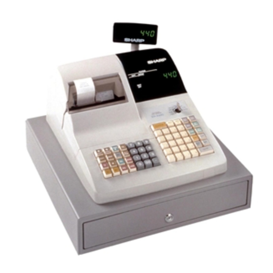
Sharp ER-A440 Service Manual
Electronic cash register
Hide thumbs
Also See for ER-A440:
- Instruction manual (130 pages) ,
- Service manual (95 pages) ,
- Programming manual (39 pages)
Advertisement
CAUTION
EXTREME CAUTION MUST BE TAKEN WHEN SERVICING THIS MACHINE. EVEN
THOUGH THE MODE SWITCH IS IN THE OFF POSITION, VOLTAGE IS STILL SUPPLIED
TO THE ENTIRE MACHINE.
WHEN WORKING ON THIS MACHINE MAKE SURE THAT THE POWER CORD IS
REMOVED FROM THE WALL OUTLET.
CHAPTER 1. SPECIFICATIONS . . . . . . . . . . . . . . . . . . . . . . . . . . . . . . . . . . 1-1
CHAPTER 2. OPTIONS . . . . . . . . . . . . . . . . . . . . . . . . . . . . . . . . . . . . . . . . . 2-1
CHAPTER 3. SERVICE (SRV) MODE . . . . . . . . . . . . . . . . . . . . . . . . . . . . . . 3-1
CHAPTER 4. HARDWARE DESCRIPTION . . . . . . . . . . . . . . . . . . . . . . . . . . 4-1
CHAPTER 5. TEST FUNCTION . . . . . . . . . . . . . . . . . . . . . . . . . . . . . . . . . . . 5-1
CHAPTER 6. DOWN LOAD FUNCTION . . . . . . . . . . . . . . . . . . . . . . . . . . . . 6-1
CHAPTER 7. SERVICE PRECAUTION . . . . . . . . . . . . . . . . . . . . . . . . . . . . . 7-1
CHAPTER 8. CIRCUIT DIAGRAM & PWB LAYOUT . . . . . . . . . . . . . . . . . . . 8-1
PARTS GUIDE
Parts marked with " " is important for maintaining the safety of the set. Be sure to replace these parts with specified ones
for maintaining the safety and performance of the set.
SERVICE MANUAL
ELECTRONIC
CASH REGISTER
MODEL
CONTENTS
SHARP CORPORATION
ER-A440
SRV Key
: LKGIM7113RCZZ
PRINTER
: DP-730
("U" & "A" version)
This document has been published to be used
for after sales service only.
The contents are subject to change without notice.
Advertisement
Table of Contents

Related Manuals for Sharp ER-A440


Summary of Contents for Sharp ER-A440
-
Page 1: Table Of Contents
SERVICE MANUAL ELECTRONIC CASH REGISTER ER-A440 MODEL SRV Key : LKGIM7113RCZZ PRINTER : DP-730 ("U" & "A" version) CAUTION EXTREME CAUTION MUST BE TAKEN WHEN SERVICING THIS MACHINE. EVEN THOUGH THE MODE SWITCH IS IN THE OFF POSITION, VOLTAGE IS STILL SUPPLIED TO THE ENTIRE MACHINE. -
Page 2: Chapter 1. Specifications
CHAPTER 1. SPECIFICATIONS 1. Appearance/Rating 1) Rating Power source AC 120 V 10% 50/60Hz Power consumption Standby: 11.5 W Maximum: 40 W (max.) Operating temperature 0°C~40°C (32°F~104°F) Operating humidity 10%~90% (RH) Physical dimensions, 420(W) 427(D) 292(H)mm including the drawer 16.5(W) 16.8(D) 11.5(H)in. -
Page 3: Mode Switch
Customer display (Pop-up display) 3. Mode switch Fig. 4-2 7 segment display (LED) No. of positions OP,X/Z Color of display Yellow Green X1/Z1 Character size 14.2 (H) 8.0 (W) mm PGM1 X2/Z2 PGM2 Display contents (SRV) Display (SRV') Description Position Amount Fig. - Page 4 Distance between dots: 0.353 mm (H) 0.353 mm (W) 4) Inking Journal near end sensor: Service route option Ink supply system: Ink ribbon Print speed: Approx. 3.0 lines/sec. Form: Cartridge/Endless ribbon Paper feed speed: Receipt – Approx. 30 lines/sec. Specification: Material –...
-
Page 5: Chapter 2. Options
CHAPTER 2. OPTIONS 1. System configuration (NOTE1) This symbol shows NEW MODEL ER-A440 ER-03RA LOCAL PURCHASE MASTER MACHINE OPTION RAM COMPUTER COMMERCIAL ER-01/02FD ER-04DW PRODUCT 3.5 inch FDD CABLE REMOTE DRAWER Fig. 1-1 2 – 1... - Page 6 2. Options NAME MODEL DESCRIPTION EXPANSION RAM CHIP ER-03RA 512K bytes RAM CHIP REMOTE DRAWER ER-04DW PRESETS LOADER ER-01FD/02FD FD unit KEY TOP KIT ER-11KT7 1 KYE TOP UNIT ER-12KT7 2 KYE TOP UNIT ER-22KT7 2 KYE TOP UNIT ER-11DK7G 1 DUMMY KYE KIT ER-51DK7G 1 DUMMY KYE KIT...
- Page 7 [key setup procedure] CHAPTER 3. SRV. RESET AND MASTER RESET MRS-2 Key position set Free key Free key setup executed complete. 1. SRV. reset (Program Loop Reset) Disable Used to return the machine back to its operational state after a lock- up has occurred.
-
Page 8: Chapter 4. Hardware Description
CHAPTER 4. HARDWARE DESCRIPTION 1. Hard ware block diagram STANDARD OPTIONAL ER-03RA:512KB RAM1 RAM2 512KB DRAWER 32KBx2 STANDARD GATE ARRAY PRINTER MPCA7 DP-730 OPERATER DISPLAY 256KB 1 LINE 7SEG 10DIG CUSTOMER DISPLAY 1 LINE 7SEG 7DIG CKDC8 SWITCH KEY BOARD RS232 1 ports Fig. - Page 9 2. Description of main LSI’s 2-1. CPU (HD6415108-10) 1) Pin configuration AVSS P57/STOP HD6415108-10 pin configuration Fig. 2-1 4 – 2...
- Page 10 2) Block diagram P27/A23 P26/A22 Data bus Port 1 P25/A21 P24/A20 P23/A19 P22/A18 P21/A17 P20/A16 EXTAL XTAL Clock Watch oscillator dog timer H8/500 CPU STBY Interruption controller 16bit free running Refresh controller timer x 2ch RFSH BREQ BACK Wait state 8bit timer controller WAIT...
- Page 11 3) Pin description SIGNAL SIGNAL SYMBOL FUNCTION SYMBOL FUNCTION NAME NAME RESET INPUT from CKDC WUTH /TOF Slip TOF signal (Nu) pull-up BUFFER /BOF Slip BOF signal (Nu) pull-up NON-MASKABLE INTERRUPT INPUT Printer (Dp-730) Reset signal from FOR SSP INTERRUPT INPUT MPCA /NEJ Near END signal jounal...
- Page 12 2-2. G.A (MPCA7) 1) Pin configuration EXINT0 EXINT1 PCUT EXINT2 FCUT EXINT3 STAMP RA15 SLRS RA16 SLMTD RA17 RA18 EXWAIT POFF WAIT INT1 HTS1 MCR1 SCK1 STH1 DAX1 RCKX IRRX UATX VRESC UARX SLTMG UASCK IRTX SLRST PHAI SDT7 SDT6 MA15 SDT5 TEST...
- Page 13 2) Block diagram A23~A0 IRLON ROS1 ROS2 Address decode RASEL RAS1 SSPRQ SSP comparison register External CS Image BAR. RAS2 Internal CS control RAS3 OPTCS IRTX IRRX I/R Control D0~D7 ASKRX Buffer TXDI SCKI RXDI HTS1 Multiplexer SCK1 serial select STH1 HTS2 SCK2...
- Page 14 3) Pin description Signal Signal Function Function name name Receipt side paper feed solenoid INT3 Interrupt signal (Nu) Journal side paper feed solenoid RXD2 8 bit serial port output to CPU PCUT Printer partial cut signal (NU) TXD2 8 bit serial port input from CPU FCUT Printer auto cut signal (NU) SCK2...
- Page 15 2-3. CKDC8 Signal Function name 1) Pin configulation 105 DAX2 — 106 MCR1 — 107 MCR2 — 108 WAIT Wait request signal 109 EXWAIT External wait control input signal 110 RA18 111 RA17 /RESETS /SHEN 112 GND — 113 RA16 LDRQ 114 RA15 CKDC8...
- Page 16 2) CKDC8 oscillation circuit SIGNAL SYMBOL FUNCTION NAME KEY RETURN 7 AVRF AVDD 4.19MHz /RESET /RES0 32. 768 KHz CKDC 8 4. 19 M Hz R164 330K VSS1 LDRQ LDRQ LORD REQUEST 32.768KHz EVENT READ CANCEL SHEN /SHEN OUT SHIFT ENABLE C106 C105 /RES1...
- Page 17 This circuit monitors +24V supply voltage. 0 page memory map The voltage at the (–) pin of the comparator IC3A is always main- 000000H tained to 5.1V by means of the zener diode ZD2, while +24V supply voltage is divided through the resistors R12, R13, and R14, and is applied to the (+) pin.
- Page 18 RAM area memory map 2) Block diagram 100000H Data bus ROS1 ROM1 NOT USE MPCA7 1C0000H RAS1 (Not use) (STANDARD) (OPTION) Address bus 1F0000H RAM1 RAS2 64K Byte RAS2 RAS3 RAM2 200000H RAS3 512K Byte Fig. 5-6 (OPTION) ROM control 280000H C80000H~CFFFFFH ROS2...
- Page 19 As the address detection system, the brake address register compari- 6. SSP circuit son system is employed though the mapping system was employed in the conventional monitor RAM. The address registerlocated in 1) Block diagram MPCA is always compared with the system address bus to monitor and generate NMI signal at a synchronized timing and togo to NMI This is the circuit employed to do the Special Service Preset(SSP).
- Page 20 3) SSP register access method Access to SSP break address register is performed through the tem- porary register as shown below: A19 A18 A17 A16 A15 A8 A7 Temporary Temporary Fig. 6-5 Enable flags can be accessed individually. Information on which brake register the SSP brake is detected in is Though enable register can be accessed individually, writing to read as binary data by reading address FFFFFFH (*1).
- Page 21 <Motor lock protection> Relation ship among RP/HP/DP When an abnormal load is applied to the mechanism, the DP (Dot Pulse) frequency is checked to prevent against the motor burn-out, the timing belt shift, and gear damage. If the following condition is The first HP after turning 1.5ms or above made, the CPU stops the motor rotation.
- Page 22 7) Caution 9. Key, display, time buzzer controls CAUTION If fuse F2 should be blown, the dot head solenoid may be shorted. Be MPCA7 sure to check the head impedance and driver breakdown. When fuse F2 is blown: HTS1 STH1 Remove F2, and perform the service resetting.
-
Page 23: Power Supply Circuit
2) Power off sequence 4) DISPLAY CONTROL When the CPU senses a service interruption, it performs necessary procedures for CPU stop. Then the CPU outputs a reset request to LED-display the CKDC5. (for operator) G1-G10 Reset request SA-SG,DP LED-display (for custmer) CKDC5 SHEN DON'T CARE... -
Page 24: Chapter 5. Test Function
1) This diagnostic program has been developed for diagnosing ma- CA/AT chine functions in the field. The program is contained within the ER-A440. The diagnostic program is stored in the external ROM which will 2) Functional description be executed by the CPU (H8/510) which requires the following... - Page 25 04 13 03 12 02 11 01 00 26 25 06 ER-A440 2266 <ER-A440 STANDARD KEY BOARD LAYOUT> 2) Functional description Keyboard test is performed with the sumcheck data of key code. 68 67 58 77 78 For sumcheck data, data are inputted to the upper upper four digits 66 55 56 57 48 38 befor the diagnostics code.
- Page 26 3) Check items 2) Functional description a) Check of the display in the test and the content of end print. State of the paper near end sensor is sensed and displayed. 4) Test termination 1 0 6 This check is terminated automatically. The test terminates with the test and message printed JOURNAL side Normal end...
- Page 27 3) Check items 3) Check items Check printing of the termination message. Description 4) Test termination Drawer open sensor detected. (Drawer opend) This check is terminated automatically. Drawer open sensor not detected. (Drawer closed) The test terminates with the test and message printed a) Check opening of the specified drawer.
- Page 28 2) Functional description [12] Standard ROM test Adujustment width of TPW at the test point TP1. 1) Key operation The pulse width of TPWW canw bwe adjusted using the 200K pot VR1. CA/AT 2) Functional description Sum check of the standard ROM (C00000H - C7FFFFH) is per- formed.
- Page 29 If a compare error is found in the check sequence from PASS1 to Display: PASS6, error print (error code E1) is performed. If there is no error found to the end of the last address, the operation is completed 5 0 0 normally.
-
Page 30: Chapter 6. Down Load Function
CHAPTER 6. DOWN LOAD 3. Location of connector pins FUNCTION ECR-ECR cable 9PIN D-SUB 9PIN D-SUB 1. General RAM data can be transmitted in the following two methods. Save the data before servicing as follows: Cable: 9 pin D-SUB – 9 pin D-SUB Fig. - Page 31 ECR-ER-02FD cable 5. Data format 25PIN D-SUB 9PIN D-SUB A single byte image of the RAM data to be transmitted is divided into a high order 4 bits and low order 4 bits and converted into ASCII ER-02FD code. Then, the image of the memory is sent in the following format: Data (128bytes) Memory top address: 0000H FFFFH...
- Page 32 7. Operational method 8. Saving/Loading of data to/From the FD unit Configuration 1) To prepare an ECR to receive data from another ECR or the ER-02FD, the memory size of the receiving unit must the same as 1) Turn off the power switch of the ER-02FD, and set the DIP or greater than the sending unit.
-
Page 33: Chapter 7. Service Precaution
CHAPTER 7. SERVICE PRECAUTION 1. Error code table When the following error codes are displayed, press the key and take a proper action according to the table below. Error Error status Action code Registration error Make a correct key entry. Misoperation error Make a correct key entry. - Page 34 8 – 1...
- Page 35 8 – 2...
- Page 36 8 – 3...
- Page 37 8 – 4...
- Page 38 8 – 5...
- Page 39 8 – 6...
- Page 40 8 – 7...
- Page 41 8 – 8...
- Page 42 8 – 9...
- Page 43 8 – 10...
- Page 44 8 – 11...
- Page 45 8 – 12...
- Page 46 8 – 13...
- Page 47 4. FRONT DISPLAY PWB 8 – 14...
- Page 48 8 – 15...
- Page 49 6. POP-UP DISPLAY PWB 8 – 16...
- Page 50 8 – 17...
- Page 51 8. PS PWB 8 – 18...
- Page 52 COPYRIGHT 1998 BY SHARP CORPORATION All rights reserved. Printed in Japan. No part of this publication may be reproduced, stored in a retrieval system, or transmitted, in any form or by any means, electronic, mechanical, photocopying, recording, or otherwise, without prior written permission of the publisher.