Table of Contents
Advertisement
Quick Links
© 2013 Char-Broil, LLC Columbus, GA 31902
PRODUCT GUIDE
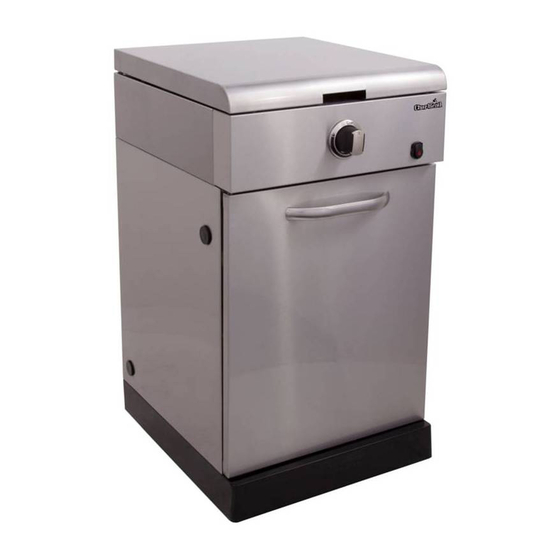
MODEL 463240613
Char-Broil Modular Stove Top Cart
IMPORTANT: Fill out the product record information below.
Serial Number
Date Purchased
For support and to register your
grill, please visit us at
www.charbroil.com
If you have questions or need
assistance during assembly,
please call 1-800-241-7548.
Printed in China
See rating label on grill for serial number.
Assembly instructions © 2013
11/20/12 • G250-001-020801
Advertisement
Table of Contents
Troubleshooting

Related Manuals for Char-Broil 463240613


Summary of Contents for Char-Broil 463240613
- Page 1 PRODUCT GUIDE MODEL 463240613 Char-Broil Modular Stove Top Cart IMPORTANT: Fill out the product record information below. Serial Number See rating label on grill for serial number. Date Purchased For support and to register your grill, please visit us at www.charbroil.com...
-
Page 2: Table Of Contents
TABLE OF CONTENTS DANGER For Your Safety ........2-3 If you smell gas: Use and Care. -
Page 3: Grease Fires
WARNING CAUTION CALIFORNIA PROPOSITION 65 Grease Fires 1. Combustible by-products produced when using this product contains chemicals known to the State • Putting out grease fires by closing the lid is not possible. Grills are well ventilated for safety reasons. of California to cause cancer, birth defects, or other reproductive harm. -
Page 4: Use And Care
LP Cylinder USE AND CARE •The LP cylinder used with your grill must meet the following requirements: DANGER •Use LP cylinders only with these required measurements: 12" (30.5cm) (diameter) x 18" (45.7 cm) (tall) with 20 lb. (9 kg.) capacity maximum. •... -
Page 5: For Your Safety
LP Cylinder Exchange Connecting Regulator to the LP Cylinder •Many retailers that sell grills offer you the option of replacing 1.LP cylinder must be properly secured onto grill. (Refer to your empty LP cylinder through an exchange service. Use only assembly section.) those reputable exchange companies that inspect, precision fill, 2.Turn all control knobs to the OFF position. - Page 6 Leak Testing Valves, Hose and Regulator 1.Turn all grill control knobs to OFF. 2.Be sure regulator is tightly connected to LP cylinder. 3.Completely open LP cylinder valve by turning hand wheel counterclockwise. If you hear a rushing sound, turn gas off immediately.
- Page 7 Safety Tips WARNING Before opening LP cylinder valve, check the coupling nut for ▲ tightness. When grill is not in use, turn off all control knobs and LP ▲ cylinder valve. For Safe Use of Your Grill and to Avoid Serious Never move grill while in operation or still hot.
- Page 8 Stove Top burner Match Lighting WARNING 1. Turn all burner control valves to the (OFF) position. 2. Open lid and leave open. Turn ON gas at LP cylinder. Turn controls and gas source or tank OFF when not 3. Place match into match holder (inside door.) in use.
-
Page 9: Spider Alert
• Stainless steel surfaces: To maintain your grill’s high quality CAUTION appearance, wash with mild detergent and warm soapy water and wipe dry with a soft cloth after each use. Baked-on grease deposits may require the use of an abrasive plastic cleaning pad. - Page 10 We suggest three ways to clean the burner tubes. Use the one Cleaning the Burner Assembly easiest for you. Follow these instructions to clean and/or replace parts of burner (A) Bend a stiff wire (a light weight coat hanger works well) assembly or if you have trouble igniting stove top.
- Page 11 NOTES...
-
Page 12: Limited Warranty
LIMITED WARRANTY This warranty only applies to units purchased from an authorized retailer. Manufacturer warrants to the original consumer-purchaser only that this product shall be free from defects in workmanship and materials after correct assembly and under normal and reasonable home use for the periods indicated below beginning on the date of purchase*. -
Page 13: Parts List
PARTS LIST Qty Description NOT Pictured TOP LID … NATURAL GAS ORIFICE KIT RUBBER BUMPER, ROUND … CASTER PIN FIREBOX … HARDWARE PACK BURNER … ASSEMBLY MANUAL, ENGLISH ELECTRODE, F/ BURNER … ASSEMBLY MANUAL, SPANISH CONTROL PANEL HOSE VALVE REGULATOR ASSEMBLY BEZEL, F/ CONTROL KNOB CONTROL KNOB IGNITER SWITCH MODULE... -
Page 14: Parts Diagram
PARTS DIAGRAM... -
Page 15: Assembly
ASSEMBLY A. Spin the casters Place bottom shelf upside down. Insert Caster Pin into the caster mounting plate to lock it in place, shown clockwise into the threads on the bottom shelf until secure. Remove the Caster Pin and repeat for remaining casters. Make sure the two locking casters are secured at the rear and the non-locking casters are secured at the front. - Page 16 Insert front brace between cart panels. Make sure door hinge pin is on the top side and facing the front. Secure front brace using two 1/4-20x1/2” screws on each side. 1/4-20x1/2" Front brace screw Right side panel Left side panel This step requires two people to lift and position stove top onto cart.
- Page 17 Connect the wire from burner electrode into the back of Electronic ignition module, positions 1. Connect the two wires [(a) and (b)] from switch wiring harness into the back of Electronic ignition module. NOTE: Switch terminals are larger than electrode terminal and should only be installed in location shown as (a),(b). Release cap and nut from electronic ignition module.
- Page 18 Attach tank exclusion wire to back panel and front brace using two #8-32x3/8" screws and #8-32 nuts. Back panel #8-32x3/8" Tank exclusion wire screw #8-32 nut #8-32 nut Note: some parts omitted for clarity of illustration Front brace #8-32x3/8" screw Attach door handle to door using two #10-24x3/8"...
- Page 19 Place cooking grate on the stove top as shown, align grate legs into matching slots in the stove top. Insert hinge pin on bottom of door into hole in bottom shelf. Press upper hinge pin in front brace, align hinge hole on top of door and release hinge pin into door.
-
Page 20: Assembly
LP CYLINDER IS SOLD SEPARATELY. Fill and leak check the cylinder before attaching to grill and regulator (see Use & Care section). Once cylinder has been filled and leak checked, place cylinder into hole in bottom shelf. Make sure cylinder valve is facing front of grill. -
Page 21: Conversion Instructions
Consumer must purchase Natural Gas Conversion Kit 4984619 to convert this grill to natural gas. Use the following instructions instead of instructions found in conversion kit Main Burner Conversion Make sure all Control Knobs are in the OFF position, LP Tank Valve is closed, Tank is disconnected from Regulator and removed from Grill. - Page 22 Pull the Burner Control Knob off of Valve Stem. Remove Screws and Washers that secure the Bezel to the Control Panel. Save removed Bezel for converting back to LP Tank Gas. Install new Natural Gas Bezel provided with Kit (see illustration below) in place of old Bezel, on Control Panel and secure using previously removed Screws and Washers.
- Page 23 Natural Gas Hose Conversion Using a wrench, not provided, remove LP Regulator Hose Assembly from Manifold Connection. Save removed LP Manifold Connection for converting back to LP Tank Gas. Your Grill may differ from illustration shown. Manifold Connection LP Regulator Hose Assembly Manifold Connection Natural Gas Hose Assembly...
- Page 24 4. When the quick disconnect socket and the gas hose are connected, WARNING a valve in the socket opens automatically to permit full gas flow. When the gas hose is disconnected, the valve in the socket instantly and positively shuts off the flow of gas. Because the valve in the Do not use hard metal piping of any kind to connect this socket positively shuts off the flow of gas, the grill can be type of grill to natural gas source.
-
Page 25: Troubleshooting
DANGER: If a gas leak cannot be stopped, or a fire occurs due to gas leakage, call the fire department. Emergencies Possible Cause Prevention/Solution Gas leaking from • Damaged hose. • Turn off gas at LP cylinder or at source on natural gas systems. If cracked/cut/burned anything but burned, replace valve/hose/regulator. - Page 26 Troubleshooting (continued) Problem Possible Cause Prevention/Solution Burner(s) will not light ELECTRONIC IGNITION: using ignitor. • No spark, no ignition noise. • See Section I of Electronic Ignition System. (See Electronic Ignition Troubleshooting also) • No spark, some ignition noise. • See Section II of Electronic Ignition System. •...
-
Page 27: Troubleshooting
Troubleshooting - Electronic Ignition Problem (Ignition) Possible Cause Check Procedure Prevention/Solution SECTION I No sparks appear at • Battery not installed • Check battery orientation. • Install battery (make sure that “+” and “–” any electrodes when properly. connectors are oriented correctly, with “+” end up Electronic Ignition Button and “–”... - Page 28 NOTES...
- Page 29 NOTES...
- Page 30 NOTES...