EnGenius EWS5912FP User Manual
Neutron series wireless management switch
Hide thumbs
Also See for EWS5912FP:
- User manual (60 pages) ,
- User manual (207 pages) ,
- Manual (74 pages)

Related Manuals for EnGenius EWS5912FP


Summary of Contents for EnGenius EWS5912FP
- Page 1 Business Solutions Business Solutions User Manual User Manual EWS5912FP EWS7928P EWS7952FP version 1.0.1 Wireless Management Switch Neutron Series...
- Page 2 IMPORTANT To install your Switch please refer to the Quick Installation Guide included in the product packaging.
-
Page 3: Table Of Contents
Table of Contents Chapter 1 Product Overview..........7 - Manual IP Settings & Auto DHCP Server Settings..37 Introduction/Package Contents..........8 - Active Clients................ 39 - Access Point Clusters............. 41 Technical Specifications.............. 9 Physical Interface................12 - General/Global Settings............42 Compatibility................... - Page 4 - Trouble Shooting................ 61 - E dge Ports ................... 9 4 - Choosing an Access Point to Diagnose......61 - CIST Instance Settings............ 95 - Bulk Upgrade................63 - CIST Port Settings.............. 97 - Device List ................... 63 - MST Instance Settings.............. 99 - MST Port Settings..............102 Chapter 3 Switch Management..........
- Page 5 - Global Settings................129 - Bandwidth Control..............160 - OUI Settings.................130 - Storm Control................161 - Port Settings................131 Security................... 162 Management.................132 - 802.1X..................162 - System Info................132 - Global Settings................163 - User Management..............133 - Port Settings................164 - File Management..............134 - Authenticated Host..............166 - Radius Server................167 - Configuration Manager............134 - Dual Image..................135 - Access....................169 - SNMP....................136...
- Page 6 - Remote Logging................ 188 - Log Table..................189 Diagnostics................... 190 - Cable Diagnostics..............190 - Ping Test..................191 - Ping Test Settings..............191 - IPv6 Ping Test................ 192 - Trace Route................193 Chapter 4 Maintenance............194 Maintenance................ 195 Upgrading/Resetting............... 196 Rebooting/Logging Out............ 197 Appendix................198 Quick Reference Guide............199 Professional Installation Instruction (English/French). 200 FCC Interference Statement..........202 IC Interference Statement............. 203 CE Interference Statement...........
-
Page 7: Chapter 1 Product Overview
Chapter 1 Product Overview... -
Page 8: Introduction/Package Contents
Features and specifications subject to change without notice. Trademarks and registered trademarks are the property of their respective owners. For United States of America: Copyright ©2014 EnGenius Technologies, Inc. All rights reserved. Compliant with FCC - This equipment has been tested and found to comply with the limits for a Class A digital device, pursuant to Part 15 of the FCC Rules. -
Page 9: Technical Specifications
Technical Specifications Standard: EWS5912FP EWS7928P EWS7952FP Ports Power budget Ports 1 - 8, output up to 30 Watts Ports 1 - 24, output up to 30 Ports 1 - 48, output up to 30 per Port Watts per Port Watts per Port... - Page 10 Port Functions: L2 Features: 8, 24, or 48 10/100/1000Mbps Ports in the front panel 802.3ad compatible Link Aggregation (Depending on model) 802.1D Spanning Tree (STP) 2 or 4 100/1000Mbps SFP Ports (Depending on model) 802.1w Rapid Spanning Tree (RSTP) 1 RJ 45 Port 802.1s Multiple Spanning Tree (MSTP) PoE Capability: IGMP Snooping v1/v2/v3...
- Page 11 Secure Control Messaging User-defined power limit SSL Certificate Management Wireless Management Features: Local MAC Address Database Remote MAC Address Database (RADIUS) Wireless Network Management Unified Configuration Import/Export Manage up to 20(EWS5912FP) / 50(EWS7928P, EWS7952FP) Intelligent Diagnostic Access Points Bulk Firmware Upgrade AP Auto Discovery and Provisioning AP Auto IP-Assignment AP Cluster Management Wireless Configuration...
-
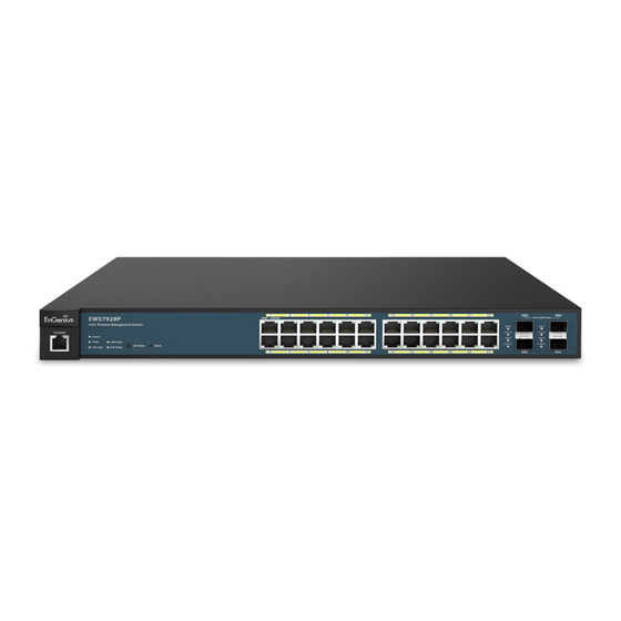
Page 12: Physical Interface
Physical Interface Dimensions Dimensions and EWS5912FP EWS7928P Width: 13” Length: 9” Height: 1.73” Width: 9.45” Length: 10.20” Height: 1.73” 12 13 EWS5912FP - Front EWS7928P - Front EWS7928P - Back EWS5912FP - Back... - Page 13 Dimensions EWS7952FP Width: 16.14” Length: 17.32” Height: 1.73” EWS7952FP -Back EWS7952FP - Front 1 RJ45 Console Port established on the port; Solid Amber Light = A valid 10/100 Mpbs link is established on the port; Solid Green Light = A valid 1000 2 Power LED: Light off = Power off;...
-
Page 14: Compatibility
Compatibility Your EWS Wireless Management Switch supports the following Access Point models: EnGenius EWS310AP Dual Band Wireless N600 Managed Indoor Access Point EnGenius EWS320AP Dual Band Wireless N900 Managed Indoor Access Point EnGenius EWS360AP Dual Band Wireless AC1750 Managed Indoor Access Point EnGenius EWS610AP Dual Band Wireless N600 Managed Outdoor Access Point... -
Page 15: Management Interface
Management Interface The Neutron Series EWS Layer 2 PoE+ Switch features an embedded Web interface for the monitoring and management of your device. -
Page 16: Connecting The Switch To A Network
Connecting the Switch to a Network Discovery in a Network with a DHCP Server 5. Open a web browser on your computer. In the address bar of the web browser, enter 192.168.0.239 and click Use this procedure to setup the Switch within a network Enter. - Page 17 Discovery on a Network without a DHCP Server (Example: 192.168.0.10 and the Subnet mask address as 255.255.255.0). This section describes how to set up the Switch in a network without a DHCP server. If your network has no DHCP service, 6. Open a web browser on your computer. In the address you must assign a static IP address to your Switch in order bar of the web browser, enter 192.168.0.239 and click to log in to the web-based Switch management.
-
Page 18: Web Access
Web Access Use this procedure to access the management interface through a Web browser for device configuration. 1. Open a Web browser on your computer and enter the following address (default): http://192.168.0.239. 2. On the login screen, use the following information: Username: admin Password: password To make access to the web-based management interface more secure, it’s highly reccomended that you change the password to something more unique. -
Page 19: Chapter 2 Controller Management
Chapter 2 Controller Management... -
Page 20: Wireless Controller & L2 Switch
Wireless Controller & Layer 2 Switch Besides functioning as a Wireless Controller, the EWS Wireless Management Switch also possesses functions of a full-featured Layer 2 PoE switch. Use the Controller/ Switch tab on the upper left corner to toggle between the Wireless Controller or Layer 2 Switch functions. -
Page 21: Device Management
Device Management Summary Managed: This shows the number of APs in the managed AP database that are configured with the EWS Switch. The Summary page shows general system information Active: This shows the number of managed for the EWS Switch including its software version, the APs that currently have an active maximum number of APs the EWS can manage, MAC connection with the EWS Switch. -
Page 22: Access Points
Access Points connected by showing or hiding columns via the search bar or checking the corresponding box. The EWS Wireless Management Switch is able to manage supported EnGenius Access Points. For the discovery proce- dure to succeed, the EWS Switch and the EWS Access point must be connected in the same network. The EWS Switch... - Page 23 Refresh Countdown Timer: This is the time left before the page auto-refreshes. The countdown is from 15 seconds. Managed: This is the number of Access Points in the managed Access Point database that are configured to the Controller. Active: This is the number of Access Points that currently have an active connection with the Controller. Offline: This is the number of Access Points that currently do not have an active connection with the Controller.
- Page 24 Model Name: Shows the model name of the managed Access Point. MAC Address: Shows the MAC address of the managed Access Point. Device Name: Displays the device name of the managed Access Point. Click on this field and you’ll be redirected to the configuration page where you can edit settings such as device name, IP Address, Wireless Radio settings, SSID, etc. IP Address: Shows the IP Address of the managed Access Point. Firmware Version: Shows the firmware version of the managed Access Point.
-
Page 25: General/Global Settings
General Global Settings Select an Access Point to configure. Next, fill in the giv- From here you can view and configure general device in- en information for the Access Point. formation for selected Access Points that are connected to the network. Device Name: The device name of the Access Point. Users can enter a custom name for the Access Point if they wish. - Page 26 DHCP: You can choose to auto assign IP Address if there is a DHCP server in the network. Static: If you wish to manually assign the IP Address, choose “Static”. Enter the IP Address you wish to assign to the AP and fill in the subnet mask and default gateway (enter DNS server address if necessary) Auto-Configuration:...
-
Page 27: How To Add Access Points To An Access Point List
How to Add Access Points to the Managed Access Point List DHCP: You can choose to auto assign an IP Address if there 1. Access Points in the network will be automatically is a DHCP server in the network. discovered by the EWS and will be listed in the AP(s) Static: If you wish to manually assign the IP Address, choose Detected list. -
Page 28: Individual Access Points Settings
Individual Access Point Settings Click on the Device Name field of the Access Point you wish to configure and you will be directed to a screen where you can configure settings for the Access Point. Click APPLY to update the system settings. -
Page 29: Wireless Radio Settings 2.4 Ghz/5 Ghz
Wireless Radio Settings 2.4 GHz Settings 5 GHz Settings Under 2.4 GHz Settings, you can configure the radio set- Under 5 GHz Settings, you can configure the radio set- tings of the selected Access Point. tings of the selected Access Point. - Page 30 Wireless Mode: Select from the drop-down menu to set Transmit Power: Use the drop-down menu to select the the wireless mode for the Access Point. transmit power for the radio. Increasing For 2.4 GHz, the available options are the power improves performance, but if 802.11b/g/n mixed, 802.11b, 802.11b/g two or more Access Points are operating mixed, 802.11g, and 802.11n.
- Page 31 Aggregation: Select whether to enable or disable Ag- gregation for the Access Point. This func- tion merges data packets into one packet, reducing the number of packets. This also increases the packet sizes, so please keep this in mind. Aggregation is useful for increasing bandwidth throughput in environments that are prone to high error rates.
-
Page 32: Wlan Settings 2.4 Ghz/5 Ghz
WLAN Settings - 2.4GHz/5GHz Under the WLAN Settings, you can create and manage SSID configurations and profiles for the Access Points to fit your needs. A SSID is basically the name of the wireless network to which a wireless client can connect to. Multiple SSIDs allow administrators to use a single physical network to support multiple applications with different configuration requirements. Up to 8 SSIDs are The ID displays the SSID profile identifier. -
Page 33: Ssid Configuration
SSID Configuration VLAN Isolation: Select Enable to prevent wireless clients from communicating with any other device on a different VLAN. VLAN ID: Enter the VLAN ID for the SSID profile. The range is from 1~4094. Note: For the Controller to function properly, make sure that all ports (on all cascading switches as well) connected to EWS APs on the switch are configured as the same VLAN ID as the Controller’s Management VLAN ID. -
Page 34: Fast Roaming
Fast Roaming Mode: Select Open System or Shared Key. WEP Key: Select the WEP Key you wish to use. When this function is enabled, PMKSA will be distributed Input Type: Select the key type. Your available options and cached on neighboring Access Points to facilitate are ASCII and HEX. -
Page 35: Wpa2/Wpa2 Enterprise
WPA/WPA2 Enterprise WPA and WPA2 are Wi-Fi Alliance IEEE 802.11i stadards, which include AES and TKIP mechanisms. Type: Select the WPA type to use. Available options are Mixed, WPA and WPA2. Encryption: Select the WPA encryption type you would like. Your available options are: Both, TKIP(Temporal Key Integrity Protocol) and AES(Advanced Encryption Standard). -
Page 36: Advanced Settings
Advanced Settings Band Click to enable or disable the Band Steering Steering function for the Access Point. Note that the 2.4 GHz and 5 GHz SSIDs must have the same security Click on the Advanced Settings tab to further customize settings. -
Page 37: Guest Network
Guest Network Configuration Security Enable SSID: Select to enable or disable SSID broadcasting on None: Select to disable security for the Access Point. the network. WPA-PSK/ Select to enable WPA with PSK(Pre-shared key/ SSID: Specify the SSID for the current profile. This WPA2-PSK Personal mode) for the network. is the name visible on the network to wireless Type: Select the WPA type you wish to use. - Page 38 Manual IP Settings & Automatic DHCP Server Settings After enabling the Guest Network feature in the SSID Configuration page, enter IP address and Subnet mask for the Guest Network and assign an IP address range for wireless clients connecting to the Guest Network. IP address: Specify an IP address for the Guest Network. Subnet Specify the Subnet mask IP address for the Guest mask:...
-
Page 39: Active Clients
Active Clients From here, you can view information on the wireless clients that are associated with the Access Points that the EWS Switch manages. If multiple Access Points are connected to the network, use the search bar to find an Access Point by its name. - Page 40 AP Device Name: Displays the name of the Access Point which the client is connected to. AP MAC address: Displays the MAC address for the given Ac- cess Point. Model Name: Displays the model name for the Access Point. SSID: Displays the network on which the client is connected to.
-
Page 41: Access Point Clusters
AP Clusters An Access Point Cluster is a dynamic, configura- tion-aware group of Access Points in the same subnet of a network. A cluster provides a single Access Point to Edit: Edits Cluster settings for a cluster manage the group of Access Points as a single wireless network instead of a series of separate devices. -
Page 42: General/Global Settings
General The General tab displays basic information about the Access Point cluster you are managing. Name: Enter the name of the cluster. Country: Select the location of the cluster from the drop-down box. Description: Enter a brief description about the cluster such as its purpose or importance. -
Page 43: Member Settings/Autoconfiguration
Member Settings Autoconfiguration Click Add or Delete to manage the number of Access DHCP: You can choose to auto assign an IP address if Points in the cluster. there is a DHCP server in the network. Static: If you wish to manually assign the IP Address, choose “Static”. -
Page 44: Wireless Radio Settings 2.4 Ghz/5 Ghz
Radio Settings Country: Enter the country that the Access Point resides in. Override Check this selection box if you wish to configure 2.4 GHz/ 5 GHz Settings Cluster Wireless Radio Settings individually for the select Settings: Access Point. Wireless Use the drop-down menu to set the wireless mode From here, you can configure details about the cluster Mode: for the access point. - Page 45 Transmit Use the drop-down menu to select the Power: transmit power for the radio. Increasing the power improves performance, but if two or more access points are operating in the same area on the same channel, it may cause interference. Client Limits: Specify the maximum number of wireless clients that can associate with the radio.
-
Page 46: Advanced Settings
Advanced Settings Clicking on the cluster field of an Access Point will direct you to a Wireless Settings page where you can configure settings for the selected cluster. Band Click to enable or disable the Band Steering Steering function for the cluster. Note that the 2.4 GHz and 5 GHz SSIDs must have the same security settings. Manual IP Settings Fast With Fast Handover enabled, the Access Point Handover:... - Page 47 Apply: Click APPLY to update the the system settings.
-
Page 48: Visual Monitoring
The following table explains the color coding of Access Visual Monitoring Points in the topology view. Topology View Green: Online Grey: Offline From here, you can see a visual view of the topology of Yellow: Status Change the cluster in the netwrok. Use the directional pad and White: Unmanaged the plus or minus buttons to navigate your view of the... -
Page 49: Navigation Tips
Navigating Tips to scroll up, down, left, or right. Note: The EWS Switch can only generate topologies with EnGenius L2 Series switches. Non-EnGenius switch- es will be marked as “Uncontrollable LAN Switches” in to Zoom in/out. Alternatively, you can use the generated topology. -
Page 50: Map View
Map View From here, you can view a realistic representation of Ac- cess Points in the network. To find Access Points within the network, enter the Access Point name in the search bar. Click Hide AP List to hide the Access Point list on the page or AP List to show a list of connected Access Points. -
Page 51: Navigation Tips
Click AP List to reveal a list of Access Points Navigating Tips that the Controller is currently managing. Use the directional pad to scroll up, down, left, or right. Click on Save Map for the settings to take effect. Use the slider to zoom in/out. Alternatively, you can use the mouse to navigate by clicking and dragging the left mouse button. -
Page 52: Floor View/Floorplan Image
Floor View Floorplan Image From here, an administrator can add or delete a custom The Floor View feature enables an administrator to up- map or floorplan image. load custom floorplans for better network visualization of a wireless network. Multiple images can be uploaded to visualize Access Point placement on multiple floors of an office building or different branch offices within an organization. -
Page 53: Status Dashboard
Floorplan View Status Dashboard Total: Displays the total memory storage space allocated Floor View for uploading custom floorplans. Available: Display the memory storage space that is currently From this page, the administrator can place Access available. Points onto the custom uploaded image by drag- In Use: Displays the memory storage space that is ging-and-dropping markers in the Access Point list. -
Page 54: Navigation Tips/Color Legend
Navigating Tips Color Legend to scroll up, down, left, or right. Green: Online - There is an active connection with the EWS Switch. Grey: Offline - There is no active connection with the EWS Switch. to Zoom in/out. Alternatively, you can use Yellow: Status Change - Indicates that there has been a status the mouse to navigate by clicking and dragging the left change for the managed Access Point. -
Page 55: Statistics
Total, Rx, Tx: Use the buttons to toggle between Total Traffic, Statistics Rx Traffic, or Tx Traffic. Sorting: Use this button to sort the order from ascending/ descending, depending on your preference. The Statistic page provides a convenient overview of Access Points and client traffic for the network. Access Points The page displays a visual chart of the network traffic of all the Access Points managed by the EWS Switch. Click Sort to view your results for the collective usage of all Access Points on the Network. - Page 56 Place your mouse cursor over a bar in the chart to show details of the AP. Next, click on the bar to show the traf- fic of the Access Point in a chart. Total, Rx, Tx, Sort: Use the button to toggle show/hide Total Traffic, Rx Traffic, Tx Traffic and sort chronologi- cally by Traffic/Client Number. Select a time increment to monitor statistics by: 1 day or 1 week.
-
Page 57: Wireless Clients
Wireless Clients In addition to viewing information based on specific Ac- cess Points, you can view data via specific clients as well for secuirty purposes. Select the Access Point you wish to view and check whether you wish to include Tx, Rx, or total usage for the client. Next, click Sort to view your results. - Page 58 Total, Rx, Tx: Use the buttons to toggle between Total Traffic, Rx Traffic, and Tx Traffic. Sorting: Use this button to sort the order to ascending/ descending. Total, Rx, Tx: Use the buttons to toggle between Total Traffic, Rx Traffic, and Tx Traffic. Sorting: Use this button to sort the order to ascending/ descending.
-
Page 59: Maintenance
Maintenance SSL Certificate Administrators can create a self-signed SSL Certificate to secure communications between the Switch and Access Points. Note that Access Points will disconnect and re- connect using new certificate upon applying changes. Generate a New Certificate Enter the information below to generate a request for an SSL certificate for the controller. Common Name: Enter the name of the request. Organization: Enter the organizations name. -
Page 60: Certification Information
Certificate Information Click on Restore under Advance Options to restore the default SSL Certificate settings. Click APPLY to update This area will display information about the given certificate. the the system settings. Click Display Certificate Information to show the current certificate information. Advanced Options This area will show any advanced options chosen. -
Page 61: Trouble Shooting
Trouble Shooting From here, you can troubleshoot any issues you have with Access Points connected to the network. This fea- ture is designed primarily for administrators to verify and test the link route between the Switch and the Access Point. A troubleshooting solution is provided by the sys- tem so that administrators can know where the problem lies. - Page 62 The controller will run a diagnostic test for the selected Access Point. Click Start to run the test. The test take a few seconds to complete. Afterwards, the results will display on the page.
-
Page 63: Bulk Upgrade
Bulk Upgrade Model: Displays the model number of the Access Point. Firmware Version: The Bulk Upgrade feature allows administrators to up- Displays the current firmware version in use. grade the firmware of multiple Aaccess Points at the File Name: Displays the file name of the firmware same time. After selecting Bulk Upgrade under Mainte- uploaded. nance, the page will display devices that are available to Image Size: Displays the size of the firmware currently upgrade. - Page 64 Status: Displays the current status of the Access Point. Model: Displays the model number of the Access Point. Name: Displays the name of the Access Point. MAC Address: Displays the MAC address of the Access Point. IP Address: Displays the IP address of the Access Point. Firmware Version: Displays the current firmware version of the Access Point.
-
Page 65: Chapter 3 Switch Management
Chapter 3 Switch Management... -
Page 66: System
System The navigation pane at the left of the Web browser interface Search Bar contains a System tab that enables you to manage your At the top right corner of the Graphical User Interface (GUI) Switch and controller with features under the following is the search bar which you can use to find and jump to any main menu options: of the Switch or Controller management features. -
Page 67: Summary
Summary The Summary screen contains general device information about the Switch, including the device name, Firmware version, MAC address, IP address, Gateway, and System Uptime. Device Name: Displays the model name of the Switch. FW version: Displays the installed firmware version of the Switch. -
Page 68: Ip Settings
IP Settings IPv4 To be managed over the network, the Switch needs an IP Address to be assigned. The IP Settings screen contains The IP Setting screen contains fields for assigning IP fields for assigning IP addresses. IP addresses are either addresses. IP addresses are either defined as static or are defined as Static or are retrieved using the Dynamic Host retrieved using the Dynamic Host Configuration Protocol Configuration Protocol (DHCP). DHCP assigns dynamic IP (DHCP). - Page 69 Dynamic IP Address (DHCP): Enables the IP address to be configured Gateway: Enter an IP address that determines automatically by the DHCP server. where packets with a destination Select this option if you have a DHCP address outside the current subnet server that can assign the Switch an IP should be sent.
-
Page 70: Ipv6
IPv6 IPv6 State: Select whether you wish to enable Auto Configuration, DHCPv6 Client, or Static for the IPv6 address. IPv6 is a an upgraded version to IPv4, providing more Auto Configuration: Use this option to set the IPv6 address for the IPv6 network interface in Auto Con- available IP addresses as well as other benefits. To ac- figuration. The Switch will automatically cess the Switch over an IPv6 network, you must first... -
Page 71: System Time
System Time Current time: Displays the current time. Enable SNTP: Select whether to Enable or Use the System Time screen to view and adjust date and Disable the SNTP server. The system time is set via an SNTP time settings. sever. - Page 72 To configure date/time through SNMP: To configure date/time manually: 1. Next to the Enable SNTP, select Enable. 1. Next to the Enable SNTP, select Disable. 2. In the Time Zone Offset list, select by country or by 2. In the Manual Time field, use the drop-down boxes to the Coordinated Universal Time (UTC/GMT) time zone in manually select the date and time you wish to set.
-
Page 73: Port Settings
Port Settings Port: Displays the port number. Link Status: Indicates whether the link is up or down. Use this screen to view and configure Switch port settings. Mode: Select the speed and the duplex mode of the The Port Settings feature lets you change the configuration Ethernet connection on this port. of the ports on the Switch in order to find the best balance Selecting Auto (Auto-Negotiation) allows one of speed and flow control according to your preferences. - Page 74 Flow Control: A concentration of traffic on a port decreases port bandwidth and overflows buffer memory causing packet discards and frame losses. Flow Control is used to regulate transmission of signals to match the bandwidth of the receiving port. The Switch uses IEEE802.3x flow control in full duplex mode and backpressure flow control in half duplex mode.
-
Page 75: Poe
30 Watts and a total PoE budget of 130, 185, 370, or 740 Watts depending on you model for uninterrupted PoE use. To access the page, click PoE under the System menu. Ports Power Budget EWS5912FP 130 Watts EWS7928P 185 Watts EWS7952FP 740 Watts... -
Page 76: Poe Port Settings
State: • Enable – Enables the Device Discovery protocol and provides The EnGenius Layer 2 PoE+ Switches supports Power power to the device using the PoE module. The Device Discovery over Ethernet (PoE) as defined by the IEEE 802.3af and Protocol lets the device discover powered devices attached to 802.3at. - Page 77 Class(Auto): Shows the classification of the powered device. The class Status: Shows the port’s PoE status. The possible field values are: defines the maximum power that can be provided to the • Delivering Power – The device is enabled to deliver power via the port. powered device. The possible field values are: • Disabled – The device is disabled for delivering power via • Class 0 – The maximum power level at the Power Sourcing. the port.
- Page 78 Apply: Click APPLY to update the the system settings.
-
Page 79: Eee
EEE Status: Enable or Disable EEE for the specified port. there is no traffic. Click APPLY to update the system settings. Network administrators have long focused on the energy efficiency of their infrastructure, and the EnGenius Layer 2 Switch complies with the IEEE’s Energy-Efficient Ethernet (EEE) standard to give you even more control. The EEE- compliant Switch offers users the ability to utilize power that Ethernet links use only during data transmission. -
Page 80: L2 Features
L2 Features Link Aggregation A Link Aggregation Group (LAG) optimizes port usage by The L2 Feature tab exhibits complete standard-based linking a group of ports together to form a single, logical, Layer 2 switching capabilities, including: Link Aggregation, higher-bandwidth link. Aggregating ports multiplies the bandwidth and increases port flexibility for the Switch. - Page 81 When you aggregate ports, the ports and LAG must fulfill •Ports can be configured as LACP ports only if the the following conditions: ports are not part of a previously configured LAG. • All ports within a LAG must be the same media/ LACP is a dynamic protocol which helps to automate format type. the configuration and maintenance of LAG’s. The main purpose of LACP is to automatically configure individual • A VLAN is not configured on the port. links to an aggregate bundle, while adding new links and helping to recover from link failures if the need arises. • The port is not assigned to another LAG.
-
Page 82: Port Trunking
Port Trunking Group: Displays the number of the given trunk group. You can utilize up to 8 link aggregation groups and Port Trunking allows you to assign physical links to one each group consisting up to 8 ports on the Switch. logical link that functions as a single, higher-speed link, Active Ports: Displays the active participating members of the providing dramatically increased bandwidth. -
Page 83: Dynamic Lacp
Dynamic Link Aggregation: Link Aggregation Control Protocol (LACP) Link Aggregation Control Protocol (LACP) allows the exchange of information with regard to the link aggregation between the two members of aggregation. This information will be packetized in Link Aggregation Control Protocol Data Units (LACDUs). The trunk group can be configured as an active or passive LACP. -
Page 84: Lacp Settings
LACP (Link Aggregation Control Protocol) Settings Assign a system priority to run with Link Aggregation Control Protocol (LACP) and is become for a backup link if a link goes down. The lowest system priority is al- lowed to make decisions about which ports it is actively participating in in case a link goes down. -
Page 85: Lacp Timout
LACP Timeout Timeout: Select the administrative LACP timeout. • Long – Long timeout value. Link Aggregation Control Protocol (LACP) allows the exchange of information with regard to the link • Short – Short timeout value. aggregation between two members of aggregation. The Long: The LACP PDU will be sent for every 30 seconds, and LACP Time Out value is measured in a periodic interval. -
Page 86: Mirror Settings
Mirror Settings Mirror ID: A number identifying the mirror session. This Switch only supports up to 4 mirror sessions. Mirrors network traffic by forwarding copies of incoming Port: Displays the session ID for port mirroring. and outgoing packets from specific ports to a monitoring Destination Select the port for traffic purposes from source ports mirrored to this port. Port: port. The packet that is copied to the monitoring port will be the same format as the original packet. - Page 87 NOTE: You cannot mirror a faster port onto a slower port. For example, if you try to mirror the traffic from a 100 Mbps port onto a 10 Mbps port, this can cause through- put problems. The port you are copying frames from should always support an equal or lower speed than the port to which you are sending the copies.
-
Page 88: Stp
STP uses a distributed algorithm to select a bridging device that serves as the root for the spanning tree network. It does this by selecting a root port on each The Spanning Tree Algorithm (STA) can be used to bridging device to incur the lowest path cost when detect and disable network loops, and to provide backup forwarding a packet from that device to the root device. -
Page 89: Spanning Tree Loops
Spanning Tree Loops Loops occur when alternate routes exist between hosts. Loops in an extended network can cause the Switch to forward traffic indefinitely, resulting in increased traffic and reducing network efficiency. Once the STP is enabled and configured, primary links are established and duplicated links are blocked automatically. The reactivation of the blocked links is also accomplished automatically. STP provides a tree topology and other Spanning tree versions supported include STP, Multiple Spanning Tree Protocol (MSTP), and Rapid Spanning Tree Protocol (RSTP). - Page 90 Multiple Spanning Tree Protocol (MSTP) defined in IEEE RSTP on the other hand is much faster than STP. It can 802.1s, enables multiple VLANs to be mapped to redu- complete a convergence in seconds, so it greatly dimin- cethe number of spanning-tree instances needed to sup- ishes the possible impact the process can have on your port a large number of VLANs.
-
Page 91: Root Bridge
Root Bridge The Root Bridge serves as an administrative point for all Spanning Tree calculations to determine which redundant links to block in order to prevent network loops. From here, you can view all the information regarding the Root Bridge within the STP. All other decisions in a spanning tree network, such as ports being blocked and ports being put in a forwarding mode, are made regarding a root bridge. - Page 92 Root Address: Displays the Root Bridge MAC address. Root in Root Bridge refers to the base of the span- ning tree, which the Switch could be config- ured for. Priority: Displays the priority for the bridge. When Switches are running STP, each is assigned a priority. After exchanging BPDUs, the Switch with the lowest priority value becomes the root bridge.
-
Page 93: Port Settings
Port Settings Edge Port: Indicate whether the port is Enabled or Disabled. STP and RSTP help guard against the formation of loops •Yes – Designates the port as an edge port. in an Ethernet network topology. A loop occurs when nodes transmit packets to each other over more than •... -
Page 94: Edge Ports
Edge Ports An edge port changes its initial STP port state from a blocking state to a forwarding state immediately without going through listening and learning states right after the port is configured as an edge port or when its link status changes. Edge Ports are not connected to LANs that have span¬ning tree devices, so Edge Ports do not receive Bridge Protocol Data Units (BPDUs). -
Page 95: Cist Instance Settings
CIST Instance Settings The Common Instance Spanning Tree (CIST) protocol is formed by the spanning-tree algorithm running among bridges that support the IEEE 802.1w, IEEE 802.1s, and IEEE 802.1D standard. A Common and Internal Spanning Tree (CIST) represents the connectivity of the entire network and it is equivalent to a spanning tree in an STP/RSTP. - Page 96 Enter the information to set up CIST for the Switch: Maximum Age: The Max Age may be set to ensure that old information does not endlessly circulate through redundant paths in the network, preventing the effective propagation of new information. Set by the Root Bridge, this Priority: Select from the list to specify the priority value will aid in determining that the Switch...
-
Page 97: Cist Port Settings
CIST Port Settings MST ID: Select the MST ID from the list. Port: Port or trunked port identifier. Use the CIST Ports Settings page to configure and view Priority: Defines the priority used for this STA attributes for interfaces when the spanning tree port in the Spanning Tree Algorithm. If the path cost for all ports on a mode is set to STP or RSTP. - Page 98 Designated Root Bridge: Displays the Root Bridge for the CST. It is comprised using the bridge priority and the base MAC address of the bridge. Internal Root Cost: This is the cost to the CIST regional root in a region. External Root Cost: External Root Cost is the cost to the CIST root.
-
Page 99: Mst Instance Settings
VLANs. MSTP maintains contact with the global network MST Instance Settings because each instance is treated as an RSTP node in the Multiple Spanning Tree Protocol, or MSTP enables the Common Spanning Tree (CST). grouping of multiple VLANs with the same topology Click the Edit button to configure the MST settings. Next, requirements into one Multiple Spanning Tree Instance enter information for the VLAN List and choose the... - Page 100 MST ID: Displays the ID of the MST group that is Configuration This value, along with the Configuration created. A maximum of 15 groups can be set Reversion: Name, identifies the MSTP region configured for the Switch. on the Switch. Devices must have the same revision number to belong to the same region. VLAN List: Enter the VLAN ID range from for the configured VLANs to associate with the MST...
- Page 101 MST ID: Displays the ID of the MST that is created. VLAN List: Enter the VLAN ID to associate with the MST Priority: Select the bridge priority value. When Switches or bridges are running STP, each is assigned a priority. The default value is 32768. The range Click the Apply button to accept the changes or the is from 0-61440.
-
Page 102: Mst Port Settings
MST Port Settings MST ID: Displays the ID of the MST group that is created. A maximum of 15 This page displays the current MSTI configuration groups can be set for the Switch. Port: Displays port or trunked port ID. information for the Switch. From here you can update Priority: Select the bridge priority value for the port configuration for an MSTI ID. If a loop occurs,... - Page 103 Internal Root Cost: Displays the path cost to the designated Port State: Indicates the current STP state of a port. If en- root for the selected MST instance. abled, the Port State determines what forwarding action is taken regarding traffic. The possible port Designated Bridge: Displays the Bridge Identifier of the states are: bridge for the Designated Port.
-
Page 104: Mac Address Table
MAC Address Table The MAC address table contains address information that the Switch uses to forward traffic between the inbound and outbound ports. All MAC addresses in the address table are associated with one or more ports. When the Switch receives traffic on a port, it searches the Ethernet switching table for the MAC address of the destination. If the MAC address is not found, the traffic is flooded out all of the other ports associated with the VLAN. -
Page 105: Dynamic Mac Address
Dynamic MAC Address Index: Displays the index for the Dynamic MAC Address table. Port: Select the port to which the entry refers. The Switch will automatically learn the device’s MAC VID: Displays the VLAN ID corresponding to the MAC address. address and store it to the Dynamic MAC address table. -
Page 106: Lldp
LLDP Link Layer Discovery Protocol (LLDP) is the IEEE 802.1AB standard for Switches to advertise their identity, major capabilities, and neighbors on the 802 LAN. LLDP allows users to views the discovered information to identify system topology and detect faulty configurations on the LAN. LLDP is essentially a neighbor discovery protocol that uses Ethernet connectivity to advertise information to devices on the same LAN and store information about the network. -
Page 107: Global Settings
Global Settings State: Select Enabled or Disabled to activate LLDP for the Switch. Select whether to Enable or Disable the LLDP feature Transmission Interval: Enter the interval at which LLDP advertisement updates are sent. The on the Switch. Next, enter the Transmission interval, default value is 30. -
Page 108: Local Device
ID, system description, and system capability System Description: Describes the device. advertisements. Here, you can view detailed LLDP Capabilities Supported: Describes the device functions. information for the EnGenius Switch. Capabilities Enabled: Describes the device functions. Port ID Subtype: Displays the port ID type. -
Page 109: Remote Device
Remote Device LLDP devices must support chassis and port ID advertisement, as well as the system name, system ID, system description, and system capability advertisements. From here you can viewing detailed LLDP Information for the remote Switch. - Page 110 Port: Displays the port. Mode: Aggregated links can be set up manually or Chassis ID Subtype: Displays the chassis ID type. automatically. Select Static or LACP for the Link Chassis ID: Displays the chassis ID Aggregation type. of the device that is • Static – The Link Aggregation is configured transmitting the LLDP manually for the specified trunk group.
-
Page 111: Igmp Snooping
IGMP Snooping can also limit flooding of traffic to IGMP designated ports. This improves network performance by restricting the multicast packets only to Switch ports where host nodes are located. IGMP Snooping significantly reduces overall Internet Group Management Protocol (IGMP) Snooping Multicast traffic passing through your Switch. Without IGMP allows a Switch to forward multicast traffic intelligently. Snooping, Multicast traffic is treated in the same manner Multicasting is used to support real-time applications such as a Broadcast transmission, which forwards packets to all... -
Page 112: Global Settings
Global Settings Status: Select to Enable or Disable IGMP Snooping on the Switch. The Switch snoops all IGMP Click to enable or disable the IGMP Snooping feature for packets it receives to determine which the Switch. Next, select whether you wish to use V2 or segments should receive packets directed to the group address when enabled. -
Page 113: Vlan Settings
VLAN Settings VLAN ID: Displays the VLAN ID. IGMP Snooping Status: Enables or Disables the IGMP snooping Use the IGMP Snooping VLAN Settings to configure IGMP feature for the specified VLAN ID. Snooping settings for VLANs on the system. The Switch Fast Leave: Enables or Disables the IGMP snooping performs IGMP Snooping on VLANs that send IGMP Fast Leave for the specified VLAN ID. -
Page 114: Querier Settings
Querier Settings VLAN ID: Displays the VLAN ID. Querier State: Select whether to Enable or Disable IGMP snooping requires that one central Switch to pe- the IGMP querier state for the spec- ified VLAN ID. riodically query all end devices on the network to an- A querier can periodically ask their nounce their Multicast memberships and this central hosts if they wish to receive mul-... - Page 115 Oper Interval: Displays the IGMP Interval of the operational querier. Max Response Enter the maximum response Interval: time used in the queries that are sent by the snooping querier. The default is 10 seconds. Oper Max Response Display the maximum response Interval: time which used in the queries that are sent by the snooping...
-
Page 116: Group List
Group List The Group List displays VLAN ID, Group IP Address, and Members Port in the IGMP Snooping List. -
Page 117: Router Settings
Router Settings VLAN ID: Displays the VLAN ID. Router Ports Auto-Learned: The Switch will auto detect the The Router Settings shows the learned multicast router prescence of a multicast router and attached port if the port is active and a member of the forward IGMP pacets accordingly. -
Page 118: Mld Snooping
MLD Snooping MLD Snooping Status: Select to Enable or Disable MLD Snooping on the Switch. The Switch Multicast Listener Discovery (MLD) Snooping operates on snoops all MLD packets it receives to determine which segments should the IPv6 traffic level for discovering multicast listeners receive packets directed to the group on a directly attached port and performs a similar address when enabled. -
Page 119: Vlan Settings
VLAN Settings Fast Leave does not apply to a port if the Switch has learned that a multicast querier is attached to it. If the Fast Leave feature is not used, a multicast querier Fast Leave can improve bandwidth usage for a network will send a GS-query message when an MLD group leave which frequently experiences many MLD host add and message is received. The querier stops forwarding traffic... -
Page 120: Group List
Group List The Group List displays the VLAN ID, IPv6 Address, and Members Port in the MLD Snooping List. -
Page 121: Router Settings
Router Settings VLAN ID: Displays the VLAN ID. Router Ports Au- The Switch will automatically detect The Router Settings feature shows the learned multicast to-Learned: the presence of a multicast router and forward MLD packets accordingly. router attached port if the port is active and a member of Dynamic Port List: Displays router ports that have been the VLAN. -
Page 122: Jumbo Frame
If you intend to leave the local area network at high speeds, the dynamics of TCP will require you to use large frame sizes. The EnGenius Layer 2 Switch supports a Jumbo Frame size of up to 9216 bytes. Jumbo frames need to be configured to work on the ingress and egress port of each device along the end-to-end transmission path. -
Page 123: Vlan
VLAN A Virtual LAN (VLAN) is a group of ports that form a logical 802.1Q Ethernet segment on a Layer 2 Switch which provides better Each VLAN in a network has an associated VLAN ID, which administration, security, and management of multicast appears in the IEEE 802.1Q tag in the Layer 2 header traffic. A VLAN is a network topology configured according of packets transmitted on a VLAN. - Page 124 Enabled: Enables 802.1Q VLANs. This feature is enabled by default. VID: Displays the VLAN ID for which the network policy is defined. The range of the VLAN ID is from 1-494. Name: Enter the VLAN name. You can use up to 32 alphanumeric characters. Tagged Port: Frames transmitted from this port are tagged with the VLAN ID.
- Page 125 Adding, Editing, and Deleting Items in the List 5. Click the Untagged Ports text box to show the untagged ports dialog box. 6. Click a radio button in the Untagged Ports row to select To add an item to the 802.1Q list, follow these steps: a port.
-
Page 126: Pvid
PVID When an Untagged packet enters a Switch port, the PVID (Port VLAN ID) will be attached to the untagged packet and forward frames to a VLAN specified VID part of the PVID. A packet received on a given port would be assigned that port’s PVID and then be forwarded to the port that corresponded to the packet’s destination address. - Page 127 Port: Displays the VLAN ID to which the PVID tag is assigned. Configure the PVID to assign untagged or tagged frames received on the selected port. PVID: Enter the PVID value. The range is from 1-4094. Accept Type: Select Tagged Only and Untagged Only from the list. •...
-
Page 128: Management Vlan
Management VLAN Management VLAN ID: Select the VLAN ID for allows user to transfer the authority of the Switch. The Management VLAN allows users to transfer the authority of the Switch from the default VLAN to other VLAN IDs. By default, the active management VLAN ID Apply: Click Apply to update the system settings. -
Page 129: Oice V Lan
Voice VLAN Voice VLAN State: Select Enabled or Disabled for Voice VLAN on the Switch. Enhance your Voice over IP (VoIP) service by configuring Voice VLAN ID: Sets the Voice VLAN ID for the network. ports to carry IP voice traffic from IP phones on a specific Only one Voice VLAN is supported on the VLAN. Voice VLAN provides QoS to VoIP, ensuring that the Switch. -
Page 130: Oui Settings
OUI Settings Port: Enter the OUI to the Voice VLAN. The following OUI are enabled by default. The Switches determines whether a received packet is The following OUI are enabled by default. a voice packet by checking its source MAC address. VoIP • 00:E0:BB - Assigned to 3COM IP Phones. -
Page 131: Port Settings
Port Settings Port: Displays the port to which the Voice VLAN Enhance your VoIP service further by configuring ports to settings are applied. State: Select Enabled to enhance VoIP quality on carry IP voice traffic from IP phones on a specific VLAN. the selected port. The default is Disabled. Voice VLAN provides QoS to VoIP, ensuring that the quality CoS Mode: Select Src or All from the list. -
Page 132: Management
Management System Name: Enter the name you wish to use to identify the Switch. You can use up to 32 alphanumeric characters. The factory System Information default name is: EWS7228P. System Location: Enter the location of the Switch. You can The System Information screen contains general device use up to 32 alphanumeric characters. -
Page 133: User Management
User Management User Name: Enter a username. You can use up to 18 alphanumeric characters. Use the User Management page to control management Password Type: Select Clear Text or Encrypted from the list. access to the Switch based on manually configured Password: Enter a new password for accessing the user names and passwords. -
Page 134: File Management
File Management Configuration Manager The File Management feature is used for saving your current configuration to a file on your computer or a TFTP server, or to restore previously saved configuration settings to the Switch using a configuration file from Upgrade your local drive or TFTP server. First, upload the configuration file from a TFTP server to Backup the Switch. Next, upload the configuration file from your local drive to the Switch by using an HTTP session. Download the configuration file from the Switch to the TFTP server on the network. Next, download the configuration file from the Switch to your local drive by Upgrade/Backup: Select Upgrade or Backup from the list. -
Page 135: Dual Image
Dual Image Active: Selects the partition you wish to be active. Flash Partition: Displays the number of the partition. Status: Displays the partition which is currently The Switch maintains two versions of the Switch image active on the Switch. in its permanent storage. One image is the active image, Image Name: Displays the name/version number of the image... -
Page 136: Snmp
SNMP The manager is the console through which network ad- ministrators perform network management functions. Simple Network Management Protocol (SNMP) is an Application Layer protocol designed specifically for Several versions of SNMP are supported. They are v1, managing and monitoring network devices. Simple v2c, and v3. SNMPv1, which is defined in RFC 1157 “A Network Management Protocol (SNMP) is a popular Simple Network Management Protocol (SNMP)”, is a stan- protocol for network management. - Page 137 In SNMPv3, User-based Security Model (USM) authenti- In SNMPv1 and SNMPv2c, user authentication is ac- cation is implemented along with encryption, allowing complished using types of passwords called Communi- you to configure a secure SNMP environment. The SN- ty Strings, which are transmitted in clear text and not MPv3 protocol uses different terminology than SNMPv1 supported by authentication.
-
Page 138: Global Settings
Global Settings SNMP State: Enables or Disables the SMNP function. The default SNMP global state is: Enabled. Simple Network Management Protocol (SNMP) is an OSI Local Engine ID (10-64 Enter the Switch’s Engine ID for the Layer 7 (Application Layer) protocol designed specifically Characters): remote clients. A SNMPv3 engine is for managing and monitoring network devices. -
Page 139: View List
View List SNMP uses an extensible design, where the available information is defined by Management Information bases (MIBs). MIBs describe the structure of the management data of a device subsystem; they use a hierarchical namespace containing Object Identifiers View Name: Enter the view name. The view name can con- (OID) to organize themselves. Each OID identifies a tain up to 30 alphanumeric characters. -
Page 140: Group List
Group List Group Name: Enter the group name that access control rules are applied to. The group name can con- tain up to 30 alphanumeric characters. Security Mode: Selects the SNMP version (v1, v2c, v3) asso- Configure SNMP Groups to control network access on ciated with the group. the Switch by providing users in various groups with Security Level: Select the security level for the group. -
Page 141: Community List
Community List Community Name: Enter the name of SNMP community string. In SNMPv1 and SNMPv2c, user authentication is ac- Community Mode: Selected Basic or Advance from the list. Select the Advance attached to the SNMP complished using types of passwords called Community group. -
Page 142: User List
User List Privilege Mode: Select No Auth, Auth, or Priv se- curity level from the list. • No auth – Neither authen- Use the User List page to create SNMP users for authen- tication nor the privacy security tication with managers using SNMP v3 to associate them levels are assigned to the group. -
Page 143: Trap Settings/Snmp Traps
Trap Settings SNMP Traps A trap is a type of SNMP message. The Switch can send traps to an SNMP manager when an event occurs. You can restrict user privileges by specifying which por¬tions of the MIBs that a user can view. In this way, you restrict which MIBs a user can display and modify for better security. -
Page 144: Acl
match the source MAC and source IP address on a spe- cific port. ACLs are composed of Access Control Entries (ACEs), which are rules that determine traffic classifica- An Access Control List (ACL) allows you to define clas- tions. Each ACE is a considered as a single rule, and up to sifi¬cation rules or establish criteria to provide security 256 rules may be defined on each ACL, with up to 3000 to your network by blocking unauthorized users and rules globally. ACLs are used to provide traffic flow con- allowing authorized us¬ers to access specific areas or trol, restrict contents of routing updates, and determine resources. - Page 145 Server IP/Hostname: Enter the Server IP or Hostname. The Timeout: Configurable only if the notify type is Hostname can contain up to 128 alpha- Informs. Enter the amount of time the numeric characters. device waits before re-sending. The de- fault is 15 seconds. SNMP Version: Select the SNMP version from the list. Notify Type: Select the type of notification to be Retry:...
-
Page 146: Mac Acl
MAC ACL This page displays the currently-defined MAC-based ACLs profiles. To add a new ACL, click Add and enter the name of the new ACL. Index: Profile identifier. Name: Enter the MAC based ACL name. You can use up to 32 alphanumeric characters. Click the Apply button to accept the changes or the Cancel button to discard them. -
Page 147: Mac Ace
Mac-Based ACE Destination MAC Enter the destination MAC address. Value: Destination MAC Enter a MAC address mask for the Use this page to view and add rules to MAC-based ACLs. Wildcard Mask: destination MAC address. A mask of 00:00:00:00:00:00 means the bits must be matched exactly;... -
Page 148: Ipv4 Acl
IPv4 ACL Index: Displays the current number of ACLs. Name: Enter the IP based ACL name. You can use up to 32 alphanumeric characters. This page displays the currently-defined IPv4-based ACLs profiles. To add a new ACL, click Add and enter the Click the Apply button to accept the changes or the name of the new ACL. Cancel button to discard them. -
Page 149: Ipv4 Ace
Action: Select what action to take if a packet matches the criteria. IPv4-Based ACE • Permit – Forwards packets that meet the ACL criteria. Use this page to view and add rules to IPv4-based ACLs. • Deny– Drops packets that meet the ACL criteria. - Page 150 • OSPF — The Open Shortest Path First (OSPF) protocol is a link-state hierarchical interior gateway protocol (IGP) for network routing • EGP — Exterior Gateway Protocol (EGP). Layer Two (2) Tunneling Protocols. It is an an Permits exchanging routing information extension to the PPP protocol that enables ISPs between two neighboring gateway hosts in an to operate Virtual Private Networks (VPNs).
-
Page 151: Ipv6 Acl
IPv6 ACL Index: Displays the current number of ACLs. Name: Enter the IPv6 based ACL name. You can use up to 32 This page displays the currently-defined IPv6-based alphanumeric characters. ACLs profiles. To add a new ACL, click Add and enter the name of the new ACL. Click the Apply button to accept the changes or the Cancel button to discard them. -
Page 152: Ipv6 Ace
IPv6 Based ACE ACL Name: Select the ACL from the list. Sequence: Enter the sequence number which signifies the order of the specified Allows IPv6 Based Access Control Entry (ACE) to be de- ACL relative to other ACLs assigned fined within a configured ACL. to the selected interface. The valid range is from 1-2147483646, 1 being processed first. - Page 153 Click Apply to save the changes to the system. VLAN ID: Enter the VLAN ID to which the IP address is attached in IPv4-Based ACE. The range is from 1-4094. 802.1p Value: Enter the 802.1p value. The range is from from 0-7. Ethertype Value: Enter the Ethertype value.
-
Page 154: Acl Binding
ACL Binding Port: Select the port for which the ACLs are bound to. MAC ACL: The ACL is MAC address based. When an ACL is bound to an interface, all the rules that IPv4 ACL: The ACL is IP address based. have been defined for the ACL are applied to that in- IPv6 ACL: The ACL is IP address based. -
Page 155: Qos
Global Settings Quality of Service (QoS) provides the ability to implement There are two options for applying QoS information onto priority queuing within a network. QoS is a means of packets: the 802.1p Class of Service (CoS) priority field providing consistent and predictable data delivery to within the VLAN tag of tagged Ethernet frames, and Dif- the Switch by distinguishing between packets that have ferentiated Services (DiffServ) Code Point (DSCP). - Page 156 State: Select whether QoS is enabled or disabled on the switch. Scheduling Method: Selects the Strict Priority or WRR to specify the traffic scheduling method. • Strict Priority – Specifies traffic scheduling based strictly on the queue priority. • WRR – Use the Weighted Round-Robin (WRR) algorithm to handle packets in priority classes of service.
-
Page 157: Cos Mapping
CoS Mapping CoS (Class of Service): Displays the CoS priority tag values, where 0 is the lowest and 7 is the highest. Queue: Check the CoS priority tag box and select Use the Class of Service (CoS) Mapping feature to specify the Queue values for each CoS value in which internal traffic class to map to the corresponding the provided fields. Eight traffic priority... -
Page 158: Dscp Mapping
DSCP Mapping DSCP (Differentiated Displays the packet’s DSCPvalues, Services Code Point): where 0 is the lowest and 10 is the Use Differentiated Services Code Point (DSCP) Mapping highest. Queue: Check the CoS priority tag box and feature to specify which internal traffic class to map to select the Queue values for each DSCP the corresponding DSCP values. -
Page 159: Port Settings
Port Settings Port: Displays the ports for which the CoS parameters are defined. From here, you can configure the QoS port settings for CoS (Class of Service) Select the CoS priority tag values, Value: where 0 is the lowest and 7 is the high- the Switch. Select a port you wish to set and choose est. -
Page 160: Bandwidth Control
Bandwidth Control Port: Displays the ports for which the bandwidth settings are displayed. Ingress: Select to Enable or Disable ingress on the The Bandwidth Control feature allows users to define interface. the bandwidth settings for a specified port’s Ingress Ingress Rate: Enter the ingress rate in kilobits per second. The Gigabit Ethernet ports have a maximum Rate Limit and Egress Rate. -
Page 161: Storm Control
Storm Control Port: Displays the ports for which the Storm Control information is displayed. Status: Select whether Storm Control is Enabled or Disabled ingress on the interface. Storm Control limits the amount of Broadcast, Unknown Broadcast: Enter the broadcast rate in kilobits per Multicast, and Unknown Unicast frames accepted and second. -
Page 162: Security
Security 802.1X The IEEE 802.1X standard authentication uses the RADIUS (Remote Authentication Dial In User Service) protocol to validate users and provide a security standard for network access control. The user that wishes to be authenticated is called a supplicant. The actual server doing the authentication, typically a Radius server, is called the authentication server. -
Page 163: Global Settings
Global Settings When a supplicant is connected to a Switch port, the port issues an 802.1X authentication request to the attached the 802.1X supplicant. The supplicant replies with the given username and password and an authentication request is then passed to a configured Radius server. The authentication server’s user database supports Extended Authentication Protocol (EAP), which allows particular guest VLAN memberships to be defined based on each individual user. -
Page 164: Port Settings
Port Settings Port: Displays the ports for which the 802.1X information is displayed. The IEEE-802.1X port-based authentication provides a Mode: Select the Auto or Force_UnAuthorized or Force_Authorized mode from the list. security standard for network access control with Radius Re-Authentication: Select whether port reauthenticati-on is servers and holds a network port disconnected until Enabled or Disabled. - Page 165 Apply: Click Apply to update the system settings.
-
Page 166: Authenticated Host
Authenticated Host The Authenticated Host section displays the Authenticated User Name, Port, Session Time, Authenticated Method, and Mac Address. -
Page 167: Radius Server
Radius Server Radius proxy servers are used for centralized administration. Remote Authentication Dial In User Service (RADIUS) is a networking protocol that provides centralized Authentication, Authorization, and Accounting (AAA) management for users that connect and use a network service for greater convenience. Radius is a server protocol that runs in the application layer, using UDP as transport. - Page 168 Index: Displays the index for which RADIUS Server is displayed. Server IP: Enter the RADIUS Server IP address. Authorized Port: Enter the authorized port number. The default port is 1812. Accounting Port: Enter the name you wish to use to identify this Switch.
-
Page 169: Access
Enter the amount of time that elapses before Timeout: HTTP is timed out. The default is 5 minutes. The range is from 0-86400 minutes. The EnGenius Layer 2 PoE+ Switch provides a built-in HTTPS Service: Select whether the HTTP Service is Enabled browser interface that enables you to configure and or Disabled. -
Page 170: Telnet Settings
Telnet Settings Telnet Service: Select whether the Telnet Service is Enabled or Disabled. It is enabled by default. From here, you can configure and manage the Switch’s Session Timeout: Enter the amount of time that elapses Telnet protocol settings. The Telnet protocol is a before the Telnet Service is timed out. The default is 5 minutes. -
Page 171: Ssh Settings
To configure SSH settings for the Switch, first select SSH Settings whether you wish to Enable or Disable the SSH service for the Switch. Note that SSH is more secure than the Secure Shell (SSH) is a cryptographic network protocol Telnet service when deciding between which service for secure data communication network services. SSH is to use. -
Page 172: Console Settings
Console Settings Session Timeout: Enter the amount of time that elapses before Console Service is timed out. The default is 5 minutes. The range is from From here, you can configure the Console Service 0-65535 minutes. settings for the Switch. History Count: Enter the entry number for History of Console Service. -
Page 173: Port Security
Port Security Max MAC Address: Enter the maximum number of MAC Addresses that can be learned on the port. The range is from 1-256. Network security can be increased by limiting access on Port: Displays the port for which the port a specific port to users with specific MAC addresses. Port security is defined. -
Page 174: Dos
DMAC = SMAC: Select Enabled or Disabled from the list. Land: Select Enabled or Disabled from the list. DoS (Denial of Service) is used for classifying and UDP Blat: Select Enabled or Disabled from the list. blocking specific types of DoS attacks. From here, you TCP Blat: Select the Enabled or Disabled from the list. - Page 175 DMAC = SMAC: Select Enabled or Disabled from the list. Land: Select Enabled or Disabled from the list. UDP Blat: Select Enabled or Disabled from the list. TCP Blat: Select the Enabled or Disabled from the list. POD: Select the Enabled or Disable from the list.
-
Page 176: Port Settings
Port Settings Port: Displays the port for which the DoS protection is defined. From here you can configure the Port Settings for DoS DoS Protection: Select Enabled or Disabled for the DoS for the Switch. Select from the drop down list whether Protection feature for the selected port. you wish to Enable or Disable DoS Protection for the Switch. -
Page 177: Monitoring
Monitoring Port: Displays the port for which statistics are displayed. RXByte: Displays the number of all packets received on the port. Port Statistics RXUcast: Displays the number of Unicast packets received on the port. The Port Statistics section displays a summary of all port RXNUcast: Displays the number of Unicast packets received on traffic statistics regarding the monitoring features on the port. -
Page 178: Rmon
RMON Index: Enter the entry number for Event. Event Type: Select the event type. • Log – The event is a log entry. Remote Network Monitoring, or RMON is used for sup- • SNMP Trap – The event is a trap. port monitoring and protocol analysis of LANS by en- • Log &... -
Page 179: Event Log Table
Event Log Table Event Log Table: Select the index of the Event Log from the list. From here, you can view specific Event logs for the Switch. Choose an Event log you wish to view fromt he Click the Apply button to accept the changes or the drop-down list. Cancel button to discard them. -
Page 180: Alarm List
Alarm List Index: Enter the entry number for the History Log Table. Sample Port: Select the port from which the You can configure Network alarms to occur when a net- alarm samples were taken. work problem is detected. Choose your preferences for Sample Variable: Select the variable of samples for the speci- the alarm from the drop-down boxes. -
Page 181: History List
History List Index: Enter the entry number for the History Log Table. The RMON History List screen contains information Sample Port: Select the port from which the history sam- ples were taken. about samples of data taken from the ports. Bucket Requested: Enter the number of samples to be saved. -
Page 182: History Log Table
History Log Table History Log Table: Select the index for the History Log from the list. From here, you can view the History Index for History Logs on the Switch. Select a History Index to view from the drop-down box. -
Page 183: Statistics
Statistics Multicast Pkts: Displays the number of good Multicast packets received on the port. From here, you can view all the packet information for CRC & Align Errors: Displays the number of CRC and Align er- rors that have occurred on the port. the controller feature of the Switch. -
Page 184: Log
Code Severity Description General Description The Syslog Protocol allows devices to send event Emergency System is unusable A emergency condition usu- notification messages in response to events, faults, or ally affecting multiple apps/ errors occurring on the platform as well as changes in servers/sites. Direct Attention is required. configuration or other occurrences across an IP network Alert Actions must be... -
Page 185: Global Settings
Global Settings From here, you can Enable or Disable the Log settings for the Switch. Logging Use the radio buttons to Enable or Disable Service: the system log. Global Logs: Select whether to Enable or Disable the Switch’s global logs for Cache, File, and Server Log. -
Page 186: Local Logging
Local Logging Target: Select Yes or No from the list. If the device is not functioning properly, an emergency log mes- From here, you can discover the paths that a packet sage is saved to the specified logging location. takes to a destination. The Switch supports log output EMERG: Select Yes or No from the list. - Page 187 Click the Apply button to accept the changes or the Cancel button to discard them.
-
Page 188: Remote Logging
Remote Logging IP/Hostname: Specify the IP address or host name of the host configured for the Syslog. From here, you can discover the paths that a packet Server Port: Specify the port on the host to which Syslog messages are sent. The default port is 514. takes to a destination. -
Page 189: Log Table
Log Table No.: A counter incremented whenever an entry to the Switch’s history log is From here, users can view and delete the history log. made. It displays the last entry (highest sequence number) first. Select the Log Target you wish to view from the drop- Timestamp: Displays the time of the log entry. -
Page 190: Diagnostics
Diagnostics Port: Select the port to which the cable is connected. Pair (A, B, C, and D): Displays the cable test results. Cable Diagnostics • Open – A cable is not connected to the port. • OK – A cable is connected to the port. Cable Diagnostics helps you to detect whether your cable Cable Length (A, B, Displays the approximate cable length. -
Page 191: Ping Test
Ping Test Ping Test Settings The Packet INternet Groper (Ping)Test allows you to You can vary the test parameters by entering the data in verify connectivity to remote hosts. The Ping test the appropraite boxes. To verify accuracy of the test, it operates by sending Internet Control Message Protocol is reccomended that you run multiple tests in case of a (ICMP) request packets to the tested host and waits for... -
Page 192: Ipv6 Ping Test
IPv6 Ping Test You can vary the test parameters by entering the data in the appropraite boxes. To verify accuracy of the test, it is reccomended that you run multiple tests in case of a Send a ping request to a specified IPv6 address. Check test fault or user error. -
Page 193: Trace Route
Trace Route IP address: Enter the IP address or the host name of the sta- tion you wish the Switch to ping to. The traceroute feature is used to discover the routes that Max Hop: Enter the maximum number of hops. The range is from 2–255 and the default is 30. -
Page 194: Chapter 4 Maintenance
Chapter 4 Maintenance... -
Page 195: Maintenance
Maintenance Maintenance functions are available from the maintenance Saving Configurations bar. Maintenance functions include: saving configuration settings, upgrading firmware, resetting the configuration to factory default standards, rebooting the device, and Important: You must save any setting changes logging out of the interface. before rebooting. -
Page 196: Upgrading/Resetting
Upgrading Resetting WARNING! Backup your configuration information WARNING! The Reset function will delete all before upgrading to prevent loss of settings information. configuration information from the current device. Backup your information before starting this procedure. Follow this procedure to upgrade the Firmware. Follow this procedure to reset the Switch back to factory 1. -
Page 197: Rebooting/Logging Out
Rebooting Logging Out Follow this procedure to reboot the Switch. Follow this procedure to log out the current profile from the user interface. 1. Click to start the reboot process. 1. Click to log out of the menu. 2. When a prompt displays, click OK to confirm the reboot process or Cancel to quit the procedure. -
Page 198: Appendix
Appendix... -
Page 199: Quick Reference Guide
Quick Reference Guide Hardware Specifications Model EWS5912FP EWS7928P EWS7952FP Connectors Gigabit RJ45 Ports Gigabit SFP Ports Console Port PoE Features Standard IEEE802.3af/at (max 30w per port) PoE Ports Total PoE Budget 130 W 185 W 740 W Power Supply 100-240VAC, 50/60Hz Environent Operating Temperature: 32°... -
Page 200: Professional Installation Instruction (English/French)
Professional Installation Instruction 1. Installation Personnel This product is designed for specific application and needs to be installed by a qualified personnel who has RF and related rule knowledge. The general user shall not attempt to install or change the setting. 2. Installation Location The product shall be installed at a location where the radiating antenna can be kept at least 23cm from nearby persons in normal operating conditions to meet regulatory RF exposure requirement. - Page 201 Instructions D’installation Professionnelle 1. Installation Ce produit est destine a un usage specifique et doit etre installe par un personnel qualifie maitrisant les radiofrequences et les regles s’y rapportant. L’installation et les reglages ne doivent pas etre modifies par l’utilisateur final. 2. Emplacement D’installation En usage normal, afin de respecter les exigences reglementaires concernant l’exposition aux radiofrequences, ce produit doit etre installe de facon a respecter une distance de 23cm entre l’antenne emettrice et les personnes. 3.
-
Page 202: Fcc Interference Statement
Appendix A Federal Communication Commission Interference Statement This equipment has been tested and found to comply with the limits for a Class B digital device, pursuant to Part 15 of the FCC Rules. These limits are designed to provide reasonable protection against harmful interference in a residential installation. This equipment generates, uses, and can radiate radio frequency energy and, if not installed and used in accordance with the instructions, may cause harmful interference to radio communications. -
Page 203: Ic Interference Statement
Appendix B - IC Interference Statement Industry Canada Statement This device complies with RSS-210 of the Industry Canada Rules. Operation is subject to the following two conditions: (1) This device may not cause harmful interference, and (2) this device must accept any interference received, including interference that may cause undesired operation. - Page 204 FOR MOBILE DEVICE USAGE Radiation Exposure Statement This equipment complies with IC radiation exposure limits set forth for an uncontrolled environment. This equipment should be installed and operated with minimum distance 20cm between the radiator & your body. Pour l’utilisation de dispositifs mobiles) Déclaration d’exposition aux radiations: Cet équipement est conforme aux limites d’exposition aux rayonnements IC établies pour un environnement non contrôlé.
-
Page 205: Ce Interference Statement
Appendix C - CE Interference Statement Europe – EU Declaration of Conformity This device complies with the essential requirements of the R&TTE Directive 1999/5/EC. The following test methods have been applied in order to prove presumption of conformity with the essential requirements of the R&TTE Directive 1999/5/EC: • EN60950-1 Safety of Information Technology Equipment • EN50385... - Page 206 This device is a 5GHz wideband transmission system (transceiver), intended for use in all EU member states and EFTA countries, except in France and Italy where restrictive use applies. In Italy the end-user should apply for a license at the national spectrum authorities in order to obtain authorization to use the device for setting up outdoor radio links and/or for supplying public access to telecommunications and/or network services.
- Page 207 Français [French] Par la présente [nom du fabricant] déclare que l’appareil [type d’appareil] est conforme aux exigences essentielles et aux autres dispositions pertinentes de la directive 1999/5/CE. Italiano [Italian] Con la presente [nome del costruttore] dichiara che questo [tipo di apparecchio] è conforme ai requisiti essenziali ed alle altre disposizioni pertinenti stabilite dalla direttiva 1999/5/CE.