Table of Contents
Advertisement
www.nordictrack.com
Model No. 831.24978.0
Serial No.
Write the serial number in the space
above for reference.
Serial Number
Decal
ACTIVATE YOUR
WARRANTY
To register your product and
activate your warranty today, go
to www.nordictrackservice.com/
registration.
CUSTOMER CARE
For service at any time, go to
www.nordictrackservice.com.
Or call 1-800-TO-BE-FIT
(1-800-862-3348)
Mon.–Fri. 6 a.m.–6 p.m. MT
Sat. 8 a.m.–4 p.m. MT
Please do not contact the store.
CAUTION
Read all precautions and instruc-
tions in this manual before using
this equipment. Save this manual
for future reference.
USER'S MANUAL
Advertisement
Table of Contents

Related Manuals for NordicTrack 831.24978.0


Summary of Contents for NordicTrack 831.24978.0
- Page 1 Model No. 831.24978.0 USER’S MANUAL Serial No. Write the serial number in the space above for reference. Serial Number Decal ACTIVATE YOUR WARRANTY To register your product and activate your warranty today, go to www.nordictrackservice.com/ registration. CUSTOMER CARE For service at any time, go to www.nordictrackservice.com.
-
Page 2: Table Of Contents
TABLE OF CONTENTS WARNING DECAL PLACEMENT ............. . . 2 IMPORTANT PRECAUTIONS . -
Page 3: Important Precautions
IMPORTANT PRECAUTIONS WARNING: To reduce the risk of burns, fire, electric shock, or injury to persons, read all important precautions and instructions in this manual and all warnings on your treadmill before using your treadmill. ICON assumes no responsibility for personal injury or property damage sus- tained by or through the use of this product. - Page 4 20. The heart rate monitor is not a medical 24. Do not change the incline of the treadmill by device. Various factors, including the user’s placing objects under the treadmill. movement, may affect the accuracy of heart rate readings. The heart rate monitor is 25.
- Page 6 STANDARD SERVICE PLANS...
-
Page 7: Before You Begin
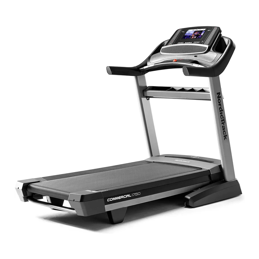
BEFORE YOU BEGIN Thank you for selecting the revolutionary reading this manual, please see the front cover of this NORDICTRACK C 900I treadmill. The C 900I tread- manual. To help us assist you, please note the product ® mill offers an impressive selection of features designed model number and serial number before contacting us. -
Page 8: Part Identification Chart
PART IDENTIFICATION CHART Use the drawings below to identify small parts used for assembly. The number in parentheses below each draw- ing is the key number of the part, from the PART LIST near the end of this manual. The number following the key number is the quantity used for assembly. -
Page 9: Assembly
ASSEMBLY • Assembly requires two persons. • To identify small parts, see page 8. • Place all parts in a cleared area and remove the • Assembly requires the following tools: packing materials. Do not dispose of the packing materials until you fi nish all assembly steps. the included hex key •... - Page 10 2. Make sure that the power cord is unplugged. Wire Press the two Base Caps (74) into the Base (94) if they are not already in the Base. Remove the tie securing the Upright Wire (81) to the front of the Base (94). Identify the Right Upright (90).
- Page 11 4. Insert a Wheel Spacer (63) into a Front Wheel (62). Hold the Front Wheel inside the bottom of the Right Upright (90), and insert a 3/8" x 4" Screw (7) with a 3/8" Star Washer (13) into the Right Upright and the Front Wheel. Repeat this step with the Left Upright (not shown).
- Page 12 6. Remove and save the four 5/16" x 3/4" Screws (4) from the Uprights (89, 90); the Screws will be used in a later step. Identify the Left and Right Base Covers (82, 83). Slide the Left Base Cover onto the Left Upright (89), and slide the Right Base Cover onto the Right Upright (90).
- Page 13 8. Attach a Handrail (86) to the Right Upright (90) with two 5/16" x 2 1/2" Screws (28) and two 5/16" Star Washers (11). Be careful not to pinch the Upright Wire (81). Do not fully tighten the Screws yet. Attach the other Handrail (86) to the Left Upright (89) in the same way.
- Page 14 10. Set the console assembly face down on a soft surface to avoid scratching the console assembly. Attach the Right and Left Trays (27, 36) with eight #8 x 1/2" Screws (1). Do not overtighten the Screws. Remove the four indicated 1/4" x 1/2" Screws (31) from the Console Frame (18);...
- Page 15 12. With the help of a second person, hold the con- sole assembly near the right Handrail (86). Console Assembly Make sure that the Upright Wire (81) is inserted through the two looped Cable Ties (99). Route the Upright Wire (81) as shown, and insert the Upright Wire into the gap indicated by the arrow.
- Page 16 14. Set the Console (80) onto the Console Base (64). Make sure that none of the wires from the Console are pinched. Attach the Console (80) to the Console Base (64) with six #8 x 3/4" Screws (2). Wires 15. Connect the ground wires (E), the 8-pin wires (F), the 10-pin wires (G), and the four speaker wires (H).
- Page 17 16. See the side view drawing. Slide the Console Base Back (104) upward to the handrail assem- bly (I). Make sure that the flange on the Console Base Back slides into the handrail assembly. Note: You will need to tip the Console Base Back (104) so that the flange can fit into the handrail assembly (I).
- Page 18 18. Carefully slide the Upright Crossbar (41) between the Uprights (89, 90). Attach the Upright Crossbar with the four 5/16" x 3/4" Screws (4) that you removed in step 6 and four 5/16" Star Washers (11). Start all four Screws, and then tighten them.
- Page 19 20. Orient the Storage Latch (53) so that the decal is facing away from the treadmill as shown. Attach the lower end of the Storage Latch (53) to the bracket on the Base (94) with a 5/16" x 1 3/4" Bolt (6) and a 5/16"...
-
Page 20: The Chest Heart Rate Monitor
THE CHEST HEART RATE MONITOR HOW TO PUT ON THE HEART RATE MONITOR • Do not expose the heart rate monitor to direct sun- light for extended periods of time; do not expose it to The heart rate temperatures above 122° F (50° C) or below 14° F monitor consists of (-10°... -
Page 21: Operation And Adjustment
OPERATION AND ADJUSTMENT HOW TO CONNECT THE POWER CORD nominal 120-volt circuit capable of carrying 15 or more amps. To avoid overloading the circuit, do Use a Surge Suppressor not plug other electrical devices, except for low- power devices such as cell phone chargers, into Your treadmill, like other electronic equipment, can be the surge suppressor or into an outlet on the same damaged by sudden voltage changes in your home’s... -
Page 22: Features Of The Console
CONSOLE DIAGRAM FEATURES OF THE CONSOLE You can even listen to your favorite workout music or audio books with the console’s sound system while you The treadmill console offers an impressive array of exercise. features designed to make your workouts more effec- tive and enjoyable. -
Page 23: To Turn On The Power
HOW TO TURN ON THE POWER HOW TO USE THE MANUAL MODE IMPORTANT: If the treadmill has been exposed to 1. Insert the key into the console. cold temperatures, allow it to warm to room tem- perature before you turn on the power. If you do See HOW TO TURN ON THE POWER at the left. - Page 24 5. Follow your progress with the displays. Press the Home button to return to the default menu (see THE SETTINGS MODE on page 28 As you walk or run on the treadmill, the display can to set the default menu). If necessary, press the show the following workout information: Home button again.
- Page 25 7. Turn on the fan if desired. When you select an onboard workout, the display will show the duration of the workout and the name The fan features several speed settings and an of the workout. In addition, a profile of the speed auto mode.
- Page 26 Note: The calorie goal is an estimate of the HOW TO USE A SET-A-GOAL WORKOUT number of calories that you will burn during the workout. The actual number of calories 1. Insert the key into the console. that you burn will depend on various factors such as your weight.
- Page 27 HOW TO USE AN IFit WORKOUT When you select an iFit workout, the display will show the duration of the workout, the distance you Note: To use an iFit workout, you must have an will walk or run, and the approximate number of optional iFit module.
- Page 28 7. Measure your heart rate if desired. THE SETTINGS MODE See step 6 on page 24. The console features an information mode that keeps track of treadmill information and allows you to person- 8. Turn on the fan if desired. alize console settings.
- Page 29 CONTRAST LVL—Press the Incline increase and HOW TO ADJUST THE CUSHIONING SYSTEM decrease buttons to adjust the contrast level of the display. The treadmill features a cushioning system that reduces the impact as you walk or run on the treadmill. If a module is connected, you may also select the following screen: Remove the key from the console and unplug the...
-
Page 30: How To Fold And Move The Treadmill
HOW TO FOLD AND MOVE THE TREADMILL HOW TO FOLD THE TREADMILL HOW TO MOVE THE TREADMILL To avoid damaging the treadmill, adjust the incline Before moving the treadmill, fold it as described at the to zero before you fold the treadmill. Then, remove left. -
Page 31: Troubleshooting
TROUBLESHOOTING Most treadmill problems can be solved by following c. Remove the key from the console, and then the simple steps below. Find the symptom that reinsert it. applies, and follow the steps listed. If further assis- tance is needed, see the front cover of this manual. d. - Page 32 Locate the Reed Switch (52) and the Magnet (50) b. If the walking belt is overtightened, treadmill per- on the left side of the Pulley (49). Turn the Pulley formance may decrease and the walking belt may until the Magnet is aligned with the Reed Switch. become damaged.
- Page 33 SYMPTOM: The walking belt is off-center or slips b. If the walking belt slips when walked on, fi rst when walked on remove the key and UNPLUG THE POWER CORD. Using the hex key, turn both idler roller a. If the walking belt is off-center, fi rst remove the screws clockwise, 1/4 of a turn.
-
Page 34: Exercise Guidelines
EXERCISE GUIDELINES Burning Fat—To burn fat effectively, you must exer- WARNING: cise at a low intensity level for a sustained period of Before beginning this time. During the first few minutes of exercise, your or any exercise program, consult your physi- body uses carbohydrate calories for energy. - Page 35 SUGGESTED STRETCHES The correct form for several basic stretches is shown at the right. Move slowly as you stretch —never bounce. 1. Toe Touch Stretch Stand with your knees bent slightly and slowly bend forward from your hips. Allow your back and shoulders to relax as you reach down toward your toes as far as possible.
- Page 36 NOTES...
- Page 37 NOTES...
-
Page 38: Part List
PART LIST Model No. 831.24978.0 R0214A Key No. Qty. Description Key No. Qty. Description #8 x 1/2" Screw Reed Switch Clip #8 x 3/4" Screw Reed Switch 5/16" x 2 1/4" Bolt Storage Latch 5/16" x 3/4" Screw Drive Motor... - Page 39 Key No. Qty. Description Key No. Qty. Description Incline Stop Bracket Speaker Console Clamp Heart Rate Monitor Right Speaker Cover Incline Motor Spacer Console Base Back #6 x 1/2" Screw Console Cover #3 x 3/8" Screw #8 x 5/8" Screw –...
-
Page 40: Exploded Drawing
EXPLODED DRAWING A Model No. 831.24978.0 R0214A... - Page 41 EXPLODED DRAWING B Model No. 831.24978.0 R0214A...
- Page 42 EXPLODED DRAWING C Model No. 831.24978.0 R0214A...
- Page 43 EXPLODED DRAWING D Model No. 831.24978.0 R0214A...
-
Page 44: Ordering Replacement Parts
ORDERING REPLACEMENT PARTS To order replacement parts, please see the front cover of this manual. To help us assist you, be prepared to provide the following information when contacting us: • the model number and serial number of the product (see the front cover of this manual) •...