Table of Contents
Advertisement
www.nordictrack.com
Model No. 831.24922.0
Serial No.
Write the serial number in the space
above for reference.
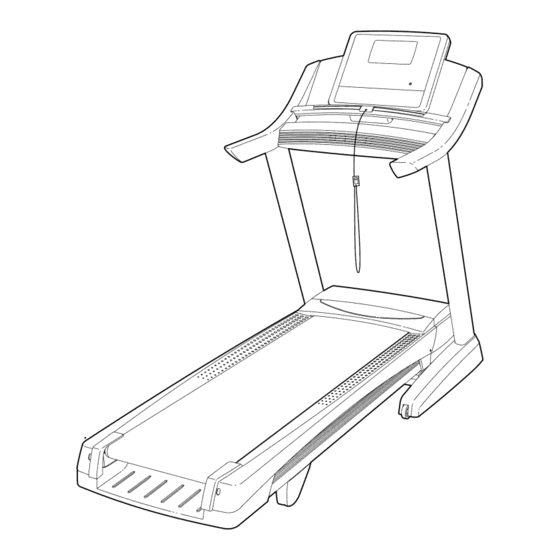
Serial
Decal
QUESTIONS?
If you have questions, or if parts
are damaged or missing, DO NOT
CONTACT THE STORE; please
contact Customer
Care.
IMPORTANT: Please register this
product (see the limited warranty
on the back cover of this manual)
before contacting Customer Care.
CALL TOLL-FREE:
1-800-TO-BE-FIT
(1-800-862-3348)
Mon.-Fri. 6 a.m.-6 p.m. MT
Sat. 8 a.m.-4 p.m. MT
ON THE WEB:
www.nordictrackservice.com
]550
USER'S MANUAL
__wlw_F
R E E
]
/f_
HOW-TO
/
_rl
I
_
V,DEOS
/
.iFit.com
_'
Advertisement
Table of Contents

Related Manuals for NordicTrack C1550 831.24922.0


Summary of Contents for NordicTrack C1550 831.24922.0
- Page 1 ]550 www.nordictrack.com Model No. 831.24922.0 USER'S MANUAL Serial No. Write the serial number in the space above for reference. Serial Decal QUESTIONS? If you have questions, or if parts are damaged or missing, DO NOT CONTACT THE STORE; please contact Customer Care.
- Page 2 FROM THISAREAWHILE THE paris.." Never try to adjust TREADMILL I S INOPERATION. or fix the belt while it is moving, - Always wear athletic NORDICTRACK is a registered trademark of ICON IP, Inc.
- Page 3 Use the treadmill only as described in this manual. the specifications described on page 13. To purchase a surge suppressor, see your local NORDICTRACK dealer, call the telephone The treadmill is intended for home use only. number on the front cover of this manual, or Do not use the treadmill in any commercial, rental, or institutional setting.
- Page 4 20. The heart rate monitor is not a medical 24. Do not change the incline of the treadmill by device. Various factors, including the user's placing objects under the treadmill. movement, may affect the accuracy of heart rate readings. The heart rate monitor is 25.
- Page 5 Thank you for selecting the revolutionary reading this manual, please see the front cover of this NORDICTRACK ® C 1550 treadmill. The C 1550 tread- manual. To help us assist you, please note the product mill offers an impressive selection of features designed model number and serial number before contacting us.
- Page 6 PART IDENTIFICATION CHART Use the drawings below to identify small parts used for assembly. The number in parentheses below each draw- ing is the key number of the part, from the PART LIST near the end of this manual. The number following the key number is the quantity used for assembly.
- Page 7 Left parts are marked "L" or "Left" and right parts mobile phone or smart- are marked "R" or "Right."...
- Page 8 Remove the tie securing the Upright Wire (78) to the left Upright (73). With the help of a second person, hold the con- sole assembly (A) near the Upright (73). Attach the console assembly (A) with four 5/16" x 1" Screws (2) and four 5/16" Star Washers (5). See the inset drawing.
- Page 9 Identify the left handrail assembly (C). Attach the left handrail assembly (C) with two 5/16" x 1 1/2" Screws (3). Start both Screws, and then tighten them. Be careful not to pinch the wires. Attach the right handrail assembly in the same way.
- Page 10 Raise the Frame (52) to the position shown. Have a second person hold the Frame until step 8 is completed. Orient the Storage Latch (49) so that the large barrel and the latch knob are in the positions shown. Attach the lower end of the Storage Latch (49) to the Upright (73) with a 3/8"...
- Page 11 Make sure that all parts are properly tightened before you use the treadmill. If there are sheets of plastic on the treadmill decals, remove the plastic. To protect the floor or carpet, place a mat under the treadmill. Note: Extra parts may be included. Keep the included hex keys in a secure place; one of the hex keys is used to adjust the walking belt (see pages 24 and 25).
- Page 12 THE CHEST HEART RATE MONITOR HOW TO PUT ON THE HEART RATE MONITOR Do not expose the heart rate monitor to direct sun- light for extended periods of time; do not expose it The heart rate to temperatures above 122 ° F (50 ° C) or below 14° monitor consists of F (-10 °...
- Page 13 OPERATION AND ADJUSTMENT HOW TO CONNECT THE POWER CORD nominal 120-volt circuit capable of carrying 15 or more amps. To avoid overloading the circuit, do Use a Surge Suppressor not plug other electrical devices, except for low- power devices such as cell phone chargers, into Your treadmill, like other electronic equipment, can be the surge suppressor or into an outlet on the same damaged by sudden voltage changes in your home's...
- Page 14 CONSOLE DIAGRAM iFIT i," ENABLED TRAIN COMPETE TRACK A GOAL LOSE ..,,o. STE_' S_'EEO STEP INCLINE I_EC{_INE °° °°,°°°°° °,°° °°°°°°° °°°°°°°°°,°° °°°°°°° °°°° °°°° °°°° °°°° °°°°°°° °°°°°°°° °,°° °°°°°°° °°,°°°°°°,°° °°°°°°° °°° ..°°°°° ..° ..°°°°°°°°°°°°°...
- Page 15 HOW TO TURN ON THE POWER HOW TO USE THE MANUAL MODE IMPORTANT: If the treadmill has been exposed to Insert the key into the console. cold temperatures, allow it to warm to room tem- See HOW TO TURN ON THE POWER at the left. perature before turning on the power.
- Page 16 Change the incline of the treadmill as desired. The My Trail tab will show a track that represents 1/4 mile (400 m). As you exercise, the flashing rect- To change the incline of the treadmill, press the angle will show your progress. The My Trail tab will Incline increase or decrease button or one of the also show the number of laps you complete.
- Page 17 Turn on the fan if desired. If desired, adjust the Increase volume by pressing the volume increase and The fan features multiple speed settings and an decrease buttons on auto mode. When the auto mode is selected, the console. the speed of the fan will automatically increase and decrease as the speed of the walking belt Decrease increases and decreases.
- Page 18 HOW TO USE AN ONBOARD WORKOUT programmed for the next segment, the speed and/ or incline setting will flash in the display and the Insert the key into the console. treadmill will automatically adjust to the new speed and/or incline setting. See HOW TO TURN ON THE POWER on page 15.
- Page 19 HOW TO USE A SET-A-GOAL WORKOUT HOW TO USE AN IFIT WORKOUT Insert the key into the console. Note: To use an iFit workout, you must have an optional iFit module. To purchase an iFit module at See HOW TO TURN ON THE POWER on page 15. any time, go to www.iFit.com or call the telephone number on the front cover of this manual.
- Page 20 For more information about the iFit workouts, Measure your heart rate if desired. please see www.iFit.com. See step 6 on page 17. When you select an iFit workout, the display will Turn on the fan if desired. show the name, duration, maximum speed setting, and distance of the workout.
- Page 21 THE INFORMATION MODE into the reset position, and insert the key into the console. However, when you remove the key, the The console features an information mode that keeps displays will remain lit, although the buttons will not function. If the demo mode is turned on, the word track of treadmill information and allows you to person- alize console settings.
- Page 22 HOW TO FOLD AND MOVE THE TREADMILL HOW TO FOLD THE TREADMILL HOW TO MOVE THE TREADMILL To avoid damaging the treadmill, adjust the incline Before moving the treadmill, fold it as described at the left. CAUTION: Make sure that the latch knob is to zero percent before you fold the treadmill.
- Page 23 TROUBLESHOOTING Most treadmill problems can be solved by follow- Remove the key from the console, and then reinsert it. ing the simple steps below. Find the symptom that applies, and follow the steps listed. If further assis- tance is needed, see the front cover of this manual. If the treadmill still will not run, please see the front cover of this manual.
- Page 24 Locate the Reed Switch (47) and the Magnet (46) If the walking belt is overtightened, treadmill per- on the left side of the Pulley (44). Turn the Pulley formance may decrease and the walking belt may until the Magnet is aligned with the Reed Switch. become damaged.
- Page 25 SYMPTOM: The walking belt is off-center or slips If the walking belt slips when walked on, first when walked on remove the key and UNPLUG THE POWER CORD. Using the hex key, turn both idler roller screws clockwise, 1/4 of a turn. When the walk- If the walking belt is off-center, first remove the key and UNPLUG THE POWER CORD.
- Page 26 EXERCISE GUIDELINES Burning Fat--To burn fat effectively, you must exer- cise at a low intensity level for a sustained period of time. During the first few minutes of exercise, your body uses carbohydrate calories for energy. Only after the first few minutes of exercise does your body begin to use stored fat calories for energy.
- Page 27 PART LIST Model No. 831.24922.0 R0912A Key No. Qty. Description Key No. Qty. Description #8 x 3/4" Screw Frame 5/16" x 1" Screw Right Rear Foot 5/16" x 1 1/2" Screw Left Rear Foot 3/8" x 1 3/4" Bolt Motor Hood 5/16"...
- Page 28 I"11 "!g I"11 _,,& 1",3 i"0 _,,& 1",3...
- Page 29 EXPLODED DRAWING B Model No. 831.24922.0 R0912A j-_-8...
- Page 30 EXPLODED DRAWING C Model No. 831.24922.0 R0912A _-8o...
- Page 31 EXPLODED DRAWING D Model No. 831.24922.0 R0912A © 1-4' © ,,'J_ "_12...
- Page 32 ORDERING REPLACEMENT PARTS To order replacement parts, please see the front cover of this manual. To help us assist you, be prepared to pro- vide the following information when contacting us: • the model number and serial number of the product (see the front cover of this manual) •...