
Related Manuals for Mitsubishi Electric PV-S4200-IT


Summary of Contents for Mitsubishi Electric PV-S4200-IT
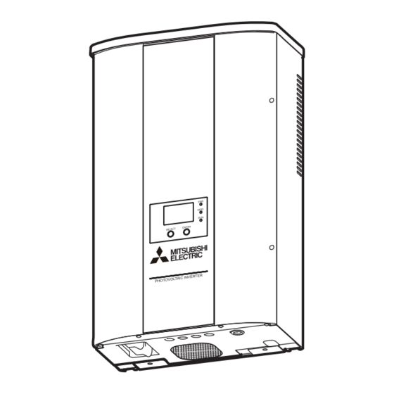
- Page 1 1004875HB0301 PHOTOVOLTAIC INVERTER MODEL PV-S4200-IT PV-S4600-IT PV-S6000-IT Manuale di funzionamento Italiano Pagina 1 - 32 Operating Manual English page 33 - 64...
- Page 3 INVERTER FOTOVOLTAICO MODELLO PV-S4200-IT PV-S4600-IT PV-S6000-IT Manuale di funzionamento Per un uso corretto e sicuro, leggere attentamente il presente Manuale di funzionamento. In particolare, leggere le Precauzioni di sicurezza. Custodire il Manuale di funzionamento in un luogo facilmente accessibile. L'inverter PV non può essere utilizzato e sottoposto a manutenzione fuori dall'Italia.
-
Page 4: Table Of Contents
Table of Contents Presentazione................................3 1 Precauzioni di sicurezza ............................4 2 Normative applicabili ..............................6 3 Configurazione del sistema di generazione di energia fotovoltaica ...............7 4 Nome delle parti ..............................8 5 Funzionamento ..............................9 5.1 Procedura di funzionamento ........................9 5.2 Controllo dello stato di funzionamento ....................... 9 5.2.1 Visualizzazione dello stato di funzionamento mediante lo schermo LCD e le spie LED ....... -
Page 5: Presentazione
Paese o regione in cui è possibile schermo LCD utilizzare il prodotto ITA:ENEL GUIDE Italia Anche se un paese è riportato nel suddetto elenco, in alcuni casi potrebbe non essere possibile utilizzare l'inverter PV. Per informazioni, contattare il rivenditore Mitsubishi Electric. -
Page 6: Precauzioni Di Sicurezza
1 Precauzioni di sicurezza I seguenti simboli denotano il tipo e il grado di pericolo che può derivare da un uso errato del dispositivo. AVVERTENZA Si tratta di pericoli che possono causare infortuni gravi o il decesso in caso di manipolazione scorretta dell'inverter PV Non lasciare irrisolte eventuali anomalie. - Page 7 Luoghi esposti ai danni da salsedine per effetto delle Questo prodotto MITSUBISHI ELECTRIC è stato progettato brezze marine e simili. e fabbricato con materiali e componenti di alta qualità, che Luoghi vicini a vulcani sulfurei, sorgenti sulfuree o zone possono essere riciclati e/o riutilizzati.
-
Page 8: Normative Applicabili
2 Normative applicabili L'inverter PV è conforme alle norme sulla compatibilità elettromagnetica (EMC) e alla direttiva sulle basse tensioni (LVD), come certificato nella dichiarazione CE. -
Page 9: Configurazione Del Sistema Di Generazione Di Energia Fotovoltaica
3 Configurazione del sistema di generazione di energia fotovoltaica Panoramica del sistema di base L'inverter PV converte l'energia DC generata dai moduli PV in energia AC e la distribuisce alla rete elettrica AC. 1 Moduli fotovoltaici (PV) Convertono l'energia fotovoltaica (PV) in corrente DC. I moduli PV sono formati da un gruppo di celle solari. -
Page 10: Nome Delle Parti
4 Nome delle parti Pannello del display Attenzione: Aperture Il pulsante [SELECT] e il pulsante [ENTER] sono interruttori ottici. di scarico Toccare e rilasciare il pulsante e rilasciarla per selezionare o confermare. Il pannello del display, che comprende uno schermo LCD, tre spie LED e due pulsanti, consente di visualizzare vari dati operativi ed eseguire le operazioni necessarie. -
Page 11: Funzionamento
5 Funzionamento Il seguente capitolo spiega come utilizzare l’inverter PV. 5.1 Procedura di funzionamento Pannello comandi Schermo LCD Procedura IN FUNZIONE Per avviare il funzionamento ITA:ENEL GUIDE Portare in posizione ON ( | ) gli interruttori TOTALE 11358kWh DC sul lato inferiore dell'inverter PV (DC1 USCITA 4321W e DC2). - Page 12 In pausa di funzionamento Schermo LCD e spie LED Descrizione L'irradiazione viene rilevata e l'unità si prepara ad avviare la ATTENDERE PREGO. . . generazione di energia elettrica. ITA:ENEL GUIDE L’inverter PV inizia a funzionare a breve. TOTALE 11358kWh USCITA MASSIMO 4508W L'irradiazione è...
-
Page 13: Se La Spia Di Errore È Accesa
In caso di errore Schermo LCD e spie LED Descrizione Eventuali anomalie nella rete elettrica AC o nell'impianto PV In caso di errore, la spia di errore (ERR) possono causare l'attivazione dei dispositivi di sicurezza, con si accende. Eseguire il "Rimedio con la l'interruzione del collegamento alla rete elettrica. -
Page 14: Display Dei Dati Operativi
5.3 Display dei dati operativi Oltre ai display dello stato di funzionamento descritti sopra, lo schermo LCD può anche visualizzare dati totali cumulativi e dati di funzionamento (per oggi, ieri, questo mese, il mese scorso, quest'anno e l'anno scorso). Schermo LCD Pressione del pulsante Bip! * Toccare il pulsante fino a udire un segnale acustico,... - Page 15 La voce del display indicata sullo schermo LCD cambia a ogni pressione del pulsante [SELECT]. Se invece non si preme alcun pulsante entro 2 minuti, viene ripristinato automaticamente il display dello stato di funzionamento corrente. I contenuti dello schermo LCD per le seguenti operazioni vengono effettivamente illustrati in visualizzazione invertita. Voce del display Schermo LCD Descrizione...
-
Page 16: Modifica E Conferma Delle Impostazioni
5.4 Modifica e conferma delle impostazioni 5.4.1 Selezione delle voci È possibile modificare e confermare le seguenti impostazioni dell'inverter PV. - Data e ora, lingua del display, prezzo unitario, indirizzo impostato, PROVA AUTO, versione software e paese impostato. Utilizzare la seguente procedura per selezionare l'impostazione da modificare e applicare le modifiche. Per i rispettivi metodi di impostazione, vedere da p.16 a p.23. - Page 17 Punto Voce Schermo LCD Procedura Impostazione prezzo Viene visualizzata la schermata «CONFIGURAZIONE CONFIGURAZIONE 1 1» illustrata nello schermo LCD a sinistra. unitario DATA/ORA LINGUA Vedere p.18 Toccare e rilasciare il pulsante [SELECT] e utilizzare PREZZO UNITÀ INDIRIZZO INV. la freccia « » per selezionare PREZZO UNITÀ. Dopo aver modificato Toccare e rilasciare il l'impostazione del prezzo...
-
Page 18: Impostazione Della Data E Dell'ora
5.4.2 Impostazione della data e dell'ora Punto Schermo LCD Procedura Viene visualizzata la schermata «CONFIGURAZIONE CONFIGURAZIONE 1 1» illustrata nello schermo LCD a sinistra. DATA/ORA LINGUA La freccia « » seleziona DATA/ORA. PREZZO UNITÀ INDIRIZZO INV. Se la voce non è selezionata, toccare e rilasciare il pulsante [SELECT] e spostare la freccia «... -
Page 19: English
5.4.3 Modifica della lingua del display Punto Schermo LCD Procedura Viene visualizzata la schermata «CONFIGURAZIONE CONFIGURAZIONE 1 1» illustrata nello schermo LCD a sinistra. DATA/ORA LINGUA Se LINGUA non è stato selezionato, toccare e PREZZO UNITÀ rilasciare il pulsante [SELECT] e utilizzare la freccia INDIRIZZO INV. -
Page 20: Impostazione Del Prezzo Unitario Per La Vendita Di Energia Elettrica
5.4.4 Impostazione del prezzo unitario per la vendita di energia elettrica Punto Schermo LCD Procedura Viene visualizzata la schermata «CONFIGURAZIONE CONFIGURAZIONE 1 1» illustrata nello schermo LCD a sinistra. DATA/ORA LINGUA Se non è stata selezionata una schermata PREZZO UNITÀ «PREZZO UNITÀ», Toccare e rilasciare il pulsante INDIRIZZO INV. -
Page 21: Configurazione Dell'interfaccia Rs485
5.4.5 Configurazione dell’interfaccia RS485 Avvertenza Richiedere sempre al rivenditore di configurare l'interruttore RS485. Se l'inverter PV viene utilizzato in combinazione con il datalogger opzionale (PV-LOG30), è assolutamente necessario impostare l'indirizzo dell'inverter PV e configurare l'interruttore RS485. Tuttavia, queste impostazioni sono necessarie solo se si utilizza la comunicazione RS485. Tenere presente che l'acquirente non può... -
Page 22: Esecuzione Della Funzione Prova Auto
5.4.6 Esecuzione della funzione PROVA AUTO L'inverter PV è dotato della funzione PROVA AUTO, che permette di controllare automaticamente i parametri OV, UV, OF e UF . Eseguire la funzione PROVA AUTO durante il funzionamento con collegamento alla rete elettrica quando l'irradiazione solare è... - Page 23 Punto Schermo LCD Procedura Eseguire PROVA AUTO della funzione di protezione OV PROVA AUTO Toccare e rilasciare il pulsante [SELECT], quindi selezionare OVR con la freccia « ». PRONTO PER PROVA Per saltare PROVA AUTO della funzione di protezione ESCI OV, toccare e rilasciare il pulsante [SELECT], quindi Toccare e rilasciare il selezionare UVR con la freccia «...
- Page 24 Punto Schermo LCD Procedura Eseguire PROVA AUTO della funzione di protezione OF PROVA AUTO Toccare e rilasciare il pulsante [SELECT], quindi selezionare OFR con la freccia « ». Per saltare PROVA AUTO della funzione di protezione PRONTO PER PROVA ESCI OF, toccare e rilasciare il pulsante [SELECT], quindi selezionare UFR con la freccia «...
-
Page 25: Controllo Della Versione Software E Del Paese Impostato
Punto Schermo LCD Procedura Completamento della modalità PROVA AUTO Toccare e rilasciare il pulsante PROVA AUTO [SELECT] una volta. Viene visualizzata la schermata «PROVA AUTO» illustrata nello schermo LCD a sinistra. ATTENDERE PREGO «CONFIGURAZIONE 2» ESCI Toccare e rilasciare il pulsante [SELECT], quindi punto 7 Toccare e rilasciare il selezionare ESCI con la freccia «... -
Page 26: Manutenzione E Riparazioni
6 Manutenzione e riparazioni Pulizia e controllo di tutti i componenti Schermo LCD dell'inverter PV ..Se sporco 6.1 Operazioni di Pulire lo schermo con un panno asciutto. Stato inverter PV ..Circa una volta all'anno manutenzione giornaliera Controllare l'eventuale presenza di guasti, interruzioni elettriche, disinnesti, rumori anomali, ecc. -
Page 27: Risoluzione Dei Problemi
6.3 Risoluzione dei problemi Si considera che la generazione massima di energia elettrica è pari a circa il 70-80% della capacità PV (i valori dipendono dall'area. Il livello può essere più basso se le aree sono in ombra o in base alle condizioni di installazione). Se la temperatura ambiente intorno all'unità... - Page 28 Procedura da seguire se viene visualizzato il messaggio ATTENZIONE Il messaggio ATTENZIONE viene visualizzato nei seguenti casi. La temperatura interna è aumentata. La data e l'ora correnti non sono impostate. IN FUNZIONE Se il messaggio ATTENZIONE viene ATTENZIONE! visualizzato sullo schermo LCD, toccare TOTALE 11358KWh e rilasciare il pulsante [ENTER] per...
-
Page 29: Dati Tecnici
7 Dati tecnici 7.1 Specifiche (1) Specifiche - Ingresso Voce PV-S4200-IT PV-S4600-IT PV-S6000-IT Campo dei valori delle tensioni ingresso DC 0 - 700 V c.c. Campo dei valori di corrente ingresso DC 0 - 9 ADC × 2 Numero di stringhe di ingresso... - Page 30 Vin=460V 0% 10% 20% 30% 40% 50% 60% 70% 80% 90% 100% 110%120% 0% 10% 20% 30% 40% 50% 60% 70% 80% 90% 100% 110%120% Tasso di potenza di uscita Tasso di potenza di uscita PV-S4200-IT 100% Vin=380V Vin=330V Vin=460V...
-
Page 31: Codici Di Errore
7.2 Codici di errore Se l'inverter PV si guasta o si verificano anomalie sulla rete, contattare il rivenditore presso il quale è stato acquistato l'inverter PV per una riparazione. I codici di errore e le relative descrizioni vengono elencati di seguito. Codice di Descrizione errore... -
Page 32: Elenco Dei Termini
8 Elenco dei termini Acronimo di corrente alternata. Importo Si riferisce all’importo di energia elettrica venduta alla società produttrice. Acronimo di corrente continua. Guasto di terra Segnala il rilevamento di una corrente che causa un guasto di terra sull’inverter PV. Energia Indica l’energia elettrica cumulativa generata dal modulo PV. -
Page 33: Registro Dell'energia Elettrica Generata
9 Registro dell'energia elettrica generata Registrare in questa colonna l'energia elettrica generata/venduta mensilmente per agevolare l'autogestione del sistema di generazione di energia elettrica PV. Si consiglia di tenere questo registro perché, se i dati vengono persi in caso di malfunzionamento dell'inverter PV, potrebbe essere impossibile recuperare i dati registrati dall'apparecchio. - Page 35 PHOTOVOLTAIC INVERTER MODEL PV-S4200-IT PV-S4600-IT PV-S6000-IT Operation Manual To ensure proper and safe use, please read this Operation Manual carefully. In particular, be sure to read the Safety Precautions. Keep this Operation Manual in an easily accessible place. The PV inverter cannot be used outside Italy, nor can servicing be performed.
- Page 36 Table of Contents Introduction ................................35 1 Safety Precautions ...............................36 2 Applicable Standards ............................38 3 Configuration of the PV Power Generation System .....................39 4 Part Names................................40 5 Operation ................................41 5.1 Operating Procedure ..........................41 5.2 Checking Operating Status ........................41 5.2.1 Operating Status Display Using LCD Screen and LED lamps ............41 5.2.2 If the Error Lamp is Lit .........................
-
Page 37: Introduction
Standard name displayed on LCD product can be used ITA:ENEL GUIDE Italy Even if a country is listed as allowing use, there may be cases in which the PV inverter cannot be used. Please inquire at a Mitsubishi Electric sales office. -
Page 38: Safety Precautions
1 Safety Precautions The following symbols denote the type and degree of danger that may result from incorrect use. WARNING These are dangers that could lead to serious injury or death if the PV inverter is mishandled Do not leave abnormalities unresolved. If strange odors or smoke are detected, use Do not open the front panel, disassemble, the DC disconnector at the bottom of the... - Page 39 2006/66/EC Article 20 Information for end-users Places near to sulfurous volcanos, sulfur springs, or and Annex II. similar regions. This MITSUBISHI ELECTRIC product is designed and Near the ceiling (in places where the temperature can manufactured with high quality materials and components exceed 50°C) which can be recycled and/or reused.
-
Page 40: Applicable Standards
2 Applicable Standards The PV inverter meets the provisions regarding electromagnetic compatibility (EMC) and the low voltage directive (LVD) as certified in the CE declaration. -
Page 41: Configuration Of The Pv Power Generation System
3 Configuration of the PV Power Generation System Overview of Basic System The PV inverter converts DC power generated by PV modules into AC power and supplies it to the AC grid. 1 Photovoltaic (PV) modules This converts photovoltaic (PV) energy into DC power. A group of solar cells makes up PV modules. -
Page 42: Part Names
4 Part Names Display panel Caution: Exhaust The [SELECT] button and [ENTER] button are optical switches. Touch openings the button and then release it to select or confirm. The display panel, which includes one LCD screen, three LED lamps, and two buttons, enables the viewing of a variety of operation data and to implement necessary operations. -
Page 43: Operation
5 Operation The following explains how to operate the PV inverter. 5.1 Operating Procedure Operation panel LCD screen Procedure RUNNING To start operation ITA:ENEL GUIDE Turn ON ( | ) the DC disconnectors at the TOTAL 11358kWh bottom of the PV inverter (DC1 and DC2). OUTPUT 4321W The current operating status is displayed... - Page 44 When on operation standby LCD screen and LED lamps Description Irradiation is detected and the unit is now preparing for the PLEASE WAIT. . . start of power generation. ITA:ENEL GUIDE The PV inverter will start operating soon. TOTAL 11358kWh OUTPUT MAXIMUM 4508W Irradiation has temporarily dropped.
-
Page 45: If The Error Lamp Is Lit
When an error occurs LCD screen and LED lamps Description Abnormalities in the AC grid or PV system cause the safety When an error occurs, the ERROR LED devices to activate, stopping grid-connected operation. lights. Perform the "If the Error Lamp is Lit"... -
Page 46: Display Of Operation Data
5.3 Display of Operation Data In addition to the operation status displays described above, the LCD screen can also display total cumulative data and operation data (for today, yesterday, this month, last month, this year, and last year). The display is locked during normal running in order to prevent abnormal operation. Be sure to release display lock in order to carry out any operation. - Page 47 The display item shown on the LCD screen will change each time the [SELECT] button is touched and released. If, however, no button is pressed within 2 minutes, the display of the current operating status will be automatically restored. LCD-screen content for the following operations is actually shown reversed. Display item LCD screen Description...
-
Page 48: Changing And Confirming Settings
5.4 Changing and Confirming Settings 5.4.1 Selecting Items The settings below can be changed and confirmed for the PV inverter. - Date and time, display language, unit price, address setting, AUTO TEST, software version, and country setting confirmation. Use the procedure below to select the setting to be changed and to implement the change. See p. 48 to p. 55 for the respective setting methods. - Page 49 Step Item LCD screen Procedure The «SETUP 1» screen as shown in the LCD screen Unit price setting SETUP 1 at left is displayed. DATE/TIME See p.50 LANGUAGE Touch and release the [SELECT] button, and use the UNIT PRICE After the unit price DEVICE ADDRESS «...
-
Page 50: Setting The Date And Time
5.4.2 Setting the Date and Time Step LCD screen Procedure The «SETUP 1» screen as shown in the LCD screen SETUP 1 at left is displayed. DATE/TIME LANGUAGE « » arrow selects DATE/TIME. UNIT PRICE DEVICE ADDRESS If not selected, touch and release the [SELECT] button and move the «... -
Page 51: Changing The Display Language
5.4.3 Changing the Display Language Step LCD screen Procedure The «SETUP 1» screen as shown in the LCD screen SETUP 1 at left is displayed. DATE/TIME LANGUAGE If a LANGUAGE has not been selected, touch and UNIT PRICE release the [SELECT] button and use the « » DEVICE ADDRESS arrow to make a selection. -
Page 52: Unit Price For Selling Energy Setting
5.4.4 Unit Price for selling Energy Setting Step LCD screen Procedure The «SETUP 1» screen as shown in the LCD screen SETUP 1 at left is displayed. DATE/TIME LANGUAGE If a «UNIT PRICE» screen has not been selected, UNIT PRICE touch and release the [SELECT] button and use the DEVICE ADDRESS «... -
Page 53: Rs485 Interface Setting
5.4.5 RS485 Interface Setting Warning Always request the sales office to perform the RS485 switch setting. When using the PV inverter in combination with the optional Data logger (PV-LOG30), it is crucial that the PV inverter address setting and the RS485 switch setting are configured. These settings are only required, however, when communicating via RS485. -
Page 54: Running Auto Test
5.4.6 Running AUTO TEST The PV inverter is equipped with an AUTO TEST for checking each of the OV, UV, OF, and UF automatically. Perform AUTO TEST during grid-connected operation when there is sufficient daytime solar irradiation. When the screen displaying the present operating status (refer to p. 42) is shown RUNNING, AUTO TEST can be implemented. - Page 55 Step LCD screen Procedure Run AUTO TEST of OV protection function AUTO TEST Touch and release the [SELECT] button, and select OVR using the « » arrow. READY FOR TEST To skip AUTO TEST of the OV protection function, EXIT Touch and release the touch and release the [SELECT] button, and select [ENTER] button once.
- Page 56 Step LCD screen Procedure Run AUTO TEST of OF protection function AUTO TEST Touch and release the [SELECT] button, and select OFR using the « » arrow. READY FOR TEST To skip AUTO TEST of the OF protection function, EXIT touch and release the [SELECT] button, and select Touch and release the UFR using the «...
-
Page 57: Confirming The Software Version And Country Setting
Step LCD screen Procedure Completion of AUTO TEST mode Touch and release the AUTO TEST [SELECT] button once. The «AUTO TEST» screen as shown in the LCD PLEASE WAIT . . . «SETUP 2» screen at left is displayed. EXIT Step 7 Touch and release the [SELECT] button, and select Touch and release the... -
Page 58: Maintenance And Repair
6 Maintenance and Repair Cleaning and Checks for All Parts PV inverter LCD screen ....When dirty 6.1 Daily Care Use a dry cloth to perform cleaning. PV inverter status ..About once each year Check for breakdowns, tilt, disengagement, rattling, Warning etc. -
Page 59: Troubleshooting
6.3 Troubleshooting Maximum power generation is considered to be approximately 70 to 80% of the PV capacity, at most. (Varies by area. The level can be even lower when areas are in shadow or due to installation conditions.) When the ambient temperature around the unit is high, output power can drop sharply. Please consult with the sales office from which the PV inverter was purchased. - Page 60 Action to take when WARNING is displayed WARNING! is displayed in the following situations. The internal temperature has risen. The present date and time are not set. RUNNING If WARNING! is displayed on the WARNING! LCD screen, touch and release TOTAL 11358KWh the [ENTER] button to display the...
-
Page 61: Technical Data
7 Technical Data 7.1 Specifications (1) Input specifications Item PV-S4200-IT PV-S4600-IT PV-S6000-IT DC input voltage range 0 - 700 VDC DC input current range 0 - 9ADC × 2 Number of input strings (2) Output specifications Item PV-S4200-IT PV-S4600-IT PV-S6000-IT Rated output 4.2 kW... - Page 62 Vin=460V 0% 10% 20% 30% 40% 50% 60% 70% 80% 90% 100% 110%120% 0% 10% 20% 30% 40% 50% 60% 70% 80% 90% 100% 110%120% Output power ratio Output power ratio PV-S4200-IT 100% Vin=380V Vin=330V Vin=460V 0% 10% 20% 30% 40% 50% 60% 70% 80% 90% 100% 110%120%...
-
Page 63: Error Codes
7.2 Error Codes If the PV inverter breaks down or a grid abnormality occurs, contact the store from which the PV inverter was purchased for repairs. Error codes and their descriptions are listed below. Error code Description E-00 Internal switch is not working properly. E-02 Relay drive pulse is abnormal. -
Page 64: List Of Terms
8 List of Terms Acronym for alternating-current. Amount Amount of electric energy sold to utility company. Acronym for direct-current. Earth fault Earth fault current detected on the PV inverter. Energy Cumulative electric energy generated by PV inverter. Input voltage Voltage input into the PV inverter. Acronym for Liquid Crystal Display. -
Page 65: Power Generation Record
9 Power Generation Record Please record the month-to-month generated energy/electric power sold in this column to assist the self-management of the PV power generation system. We recommend this record keeping because it may not be possible to recover data recorded in the equipment that is lost in the event of a PV inverter malfunction. - Page 68 Italian Representative Mitsubishi Electric Europe B.V. Via Colleoni, 7 - Centro Direzionale Colleoni 20041 Agrate Brianza (Milano) Italy http://www.mitsubishielectric.it/fotovoltaico/index.php May. 2010...