Table of Contents
Advertisement
Quick Links
Advertisement
Table of Contents

Related Manuals for Icom IC-M412


Summary of Contents for Icom IC-M412
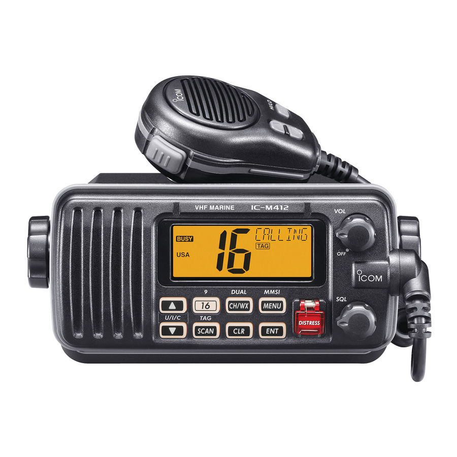
- Page 1 INSTRUCTION MANUAL VHF MARINE TRANSCEIVER iM412...
-
Page 2: Foreword
OUGHLY WITH FRESH WATER after exposure to water including salt water, otherwise, the keys and switches may Icom, Icom Inc. and the Icom logo are registered trademarks of Icom Incor- porated (Japan) in Japan, the United States, the United Kingdom, Germany, become inoperable due to salt crystallization. -
Page 3: In Case Of Emergency
IN CASE OF EMERGENCY If your vessel requires assistance, contact other vessels and Or, transmit your Distress call using digital selective calling the Coast Guard by sending a Distress call on Channel 16. on Channel 70. USING CHANNEL 16 USING DIGITAL SELECTIVE CALLING (DSC ) (Channel 70) DISTRESS CALL PROCEDURE DISTRESS CALL PROCEDURE... -
Page 4: Fcc Information
• Consult the dealer or an experienced radio/TV techni- cian for help. CAUTION: Changes or modifications to this device, not expressly approved by Icom Inc., could void your authority to operate this device under FCC regulations. -
Page 5: Supplied Accessories
SUPPLIED ACCESSORIES NOTE The following accessories are supplied; A WARNING STICKER is supplied with the transceiver. To comply with FCC regulations, this sticker must be affixed in such a location as to be readily seen from the operating controls Mounting bracket For the mounting bracket of the radio as in the diagram below. -
Page 6: Radio Operator Warning
RADIO OPERATOR WARNING Icom requires the radio operator to meet the FAILURE TO OBSERVE THESE LIMITS MAY ALLOW FCC Requirements for Radio Frequency THOSE WITHIN THE MPE RADIUS TO EXPERIENCE RF Exposure. An omnidirectional antenna with RADIATION ABSORPTION WHICH EXCEEDS THE FCC gain not greater than 9 dBi must be mounted a MAXIMUM PERMISSIBLE EXPOSURE (MPE) LIMIT. -
Page 7: Table Of Contents
TABLE OF CONTENTS 6 DSC OPERATION...............13–43 FOREWORD ..................i IMPORTANT ..................i n MMSI code programming ............13 EXPLICIT DEFINITIONS ..............i n DSC address ID ..............14 IN CASE OF EMERGENCY ............. ii n Position and time programming ..........17 FCC INFORMATION ............... iii n Position indication ..............18 SUPPLIED ACCESSORIES ............ -
Page 8: Precautions
PRECAUTIONS DO NOT RWARNING! NEVER connect the transceiver to an AC use harsh solvents such as benzine or alcohol to outlet. This may pose a fire hazard or result in an electric clean the transceiver, as they will damage the transceiver’s shock. -
Page 9: Operating Rules
OPERATING RULES D PRIORITIES (2) OPERATOR’S LICENSE A Restricted Radiotelephone Operator Permit is the license • Read all rules and regulations pertaining to priorities and most often held by small vessel radio operators when a radio keep an up-to-date copy handy. Safety and Distress calls is not required for safety purposes. -
Page 10: Panel Description
PANEL DESCRIPTION n Front panel y SCAN • TAG CHANNEL KEY Speaker Function display (p. 4) [SCAN] • [TAG](SCAN) (p. 11) ➥ Push to start and stop the Normal or Priority scan. ➥ Hold down for 1 second to set or clear the displayed channel as a tag (scanned) channel. -
Page 11: Microphone
PANEL DESCRIPTION n Microphone i CHANNEL 16/CALL CHANNEL KEY [16] • [9](16) ➥ Push to select Channel 16. (p. 5) Microphone ➥ Hold down for 1 second to select the Call channel. (p. 5) • “CALL” appears when the Call channel is selected. ➥... -
Page 12: Function Display
PANEL DESCRIPTION n Function display y DSC ICONS Indicates the DSC status. • “DSC” appears when a DSC call is received. (pp. 23, 34) • “POS REPLY” appears when a Position Reply call is received. (p. 38) u GPS ICON ➥... -
Page 13: Basic Operation
BASIC OPERATION n Channel selection ï Channel 9 (Call channel) ï Channel 16 Each regular channel group has a separate leisure-use Call Channel 16 is the distress and safety channel. It is used for channel. The Call channel is monitored during Tri-watch. The establishing initial contact with a station and for emergency Call channels can be programmed (p. -
Page 14: Weather Channels
BASIC OPERATION n Channel selection (Continued) ï Weather channels ï U.S.A., international and Canadian channels The transceiver is pre-programmed with 57 USA, 57 interna- (U.S.A. version transceiver only) tional and 61 Canadian channels. These channel groups may The transceiver has 10 weather channels. These are used be specified for the operating area. -
Page 15: Receiving And Transmitting
BASIC OPERATION n Receiving and transmitting IMPORTANT: CAUTION: To maximize the readability of your trans- Transmitting without an antenna may dam- mitted signal, pause a few seconds after holding down age the transceiver. [PTT], hold the microphone 5 to 10 cm from your mouth q Rotate [VOL] to turn ON the power. -
Page 16: Call Channel Programming
BASIC OPERATION n Call channel programming n Channel comments The Call channel is used to select Channel 9 (default). How- The channels can be labeled with a unique alphanumeric ID ever, you can program the Call channel in each channel of up to 10 characters. -
Page 17: Microphone Lock Function
BASIC OPERATION n Microphone Lock function n Display backlight The Microphone Lock function electrically locks the [Y] and The function display and keys can be backlit for better visibil- [Z] keys on the supplied microphone. This prevents acciden- ity under low light conditions. tal channel changes and function access. -
Page 18: Scan Operation
SCAN OPERATION n Scan types Set the TAG channels (scanned channel) before scanning. Scanning is an efficient way to locate signals quickly over a Clear any TAG channels which inconveniently stop scanning, wide frequency range. The transceiver has Priority scan and such as those for digital communication use. -
Page 19: Setting Tag Channels
SCAN OPERATION n Setting TAG channels n Starting a scan For more efficient scanning, you can add desired channels as First, set scan type (Priority or Normal scan) and the scan TAG channels, or remove unwanted channels as TAG channels. resume timer in the Set mode. -
Page 20: Dualwatch/Tri-Watch
DUALWATCH/TRI-WATCH n Description n Operation Dualwatch monitors Channel 16 while you are receiving on q Select Dualwatch or Tri-watch in the Set mode. (p. 46) w Push [Y] or [Z] to select a desired channel. another channel; Tri-watch monitors Channel 16 and the Call channel while receiving another channel. -
Page 21: Dsc Operation
DSC OPERATION n MMSI code programming i Push [ENT], then input the same MMSI code as step y The 9-digit MMSI (Maritime Mobile Service Identity: DSC self for the confirmation. ID) code can be programmed at power ON. o Push [ENT] to set the code. This code programming can be performed only twice. -
Page 22: Dsc Address Id
DSC OPERATION n DSC address ID t Push [Y] or [Z] to set up to a 10-character ID name. A total of 100 9-digit DSC address IDs can be programmed • Push [CH/WX] or [16] to move the cursor forward or backward. and named with up to 10 characters. -
Page 23: D Programming Group Id
DSC OPERATION D Deleting Address ID D Programming Group ID q Push [MENU] to enter the DSC menu. q Push [MENU] to enter the DSC menu. w Push [Y] or [Z] to select “ADDRESS,” then push [ENT]. w Push [Y] or [Z] to select “ADDRESS,” then push [ENT]. e Push [Y] or [Z] to select “DEL INDV ID,”... -
Page 24: D Deleting Group Id
DSC OPERATION D Deleting Group ID n DSC address ID D Programming Group ID (Continued) q Push [MENU] to enter the DSC menu. t Push [Y] or [Z] to set up to a 10-character ID name. w Push [Y] or [Z] to select “ADDRESS,” then push [ENT]. •... -
Page 25: Position And Time Programming
DSC OPERATION n Position and time programming A Distress call should include the ship’s position and time r After setting the longitude data, push [ENT] to set the cur- data. If no GPS is connected, your position and UTC (Univer- rent UTC time using [s] or [t]. -
Page 26: Position Indication
DSC OPERATION n Position indication n Distress call When a GPS receiver is connected, the transceiver displays A Distress call should be transmitted whenever, if in the opin- the current position data with an accuracy in seconds. ion of the Master, the ship or a person is in distress and re- quires immediate assistance. -
Page 27: D Regular Call
DSC OPERATION D Regular call The nature of the distress should be included in the Distress call. Scrolls q Push [MENU] to enter the DSC menu. w Push [s] or [t] to select “DISTRESS,” and then push [ENT]. r After receiving the acknowledgment, reply using the micro- phone. - Page 28 DSC OPERATION n Distress call D Regular call (Continued) r Push [s] or [t] to set your latitude data. After setting the y Push [DISTRESS] for 3 seconds to transmit the Distress latitude data, push [ENT] to set your longitude data. call.
-
Page 29: Transmitting Dsc Calls
DSC OPERATION n Transmitting DSC calls i After receiving the acknowledgment, reply using the micro- To ensure correct operation of the DSC function, please phone. make sure you set the squelch correctly. (p. 7) D Transmitting an Individual call Scrolls The Individual call function allows you to transmit a DSC sig- nal to a specific ship or a Coast station. - Page 30 DSC OPERATION n Transmitting DSC calls D Transmitting an Individual call (Continued) r Push [Y] or [Z] to select a desired intership channel, then e Push [Y] or [Z] to select a desired pre-programmed Indi- vidual address or “MANUAL INPUT,” then push [ENT]. push [ENT].
- Page 31 DSC OPERATION y Stands by on the operated channel (before entering the i Push [ENT] to select to the intership channel, specified in step DSC menu in step q), until an acknowledgement call is r, then hold down [PTT] to communicate your message to received.
- Page 32 DSC OPERATION n Transmitting DSC calls (Continued) D Transmitting an Individual acknowledgement r Push [Y] or [Z] to select the acknowledgement “ABLE” or When receiving an Individual call, you can transmit an ac- “UNABLE,” then push [ENT]. knowledgement (‘Able to comply’ or ‘Unable to comply’) by •...
-
Page 33: D Transmitting A Group Call
DSC OPERATION D Transmitting a Group call y After the Individual acknowledgement call has been trans- The Group call function allows you to transmit a DSC signal mitted, the specified channel (specified by the calling sta- to a specific group only. tion) is automatically selected when “ABLE”... - Page 34 DSC OPERATION n Transmitting DSC calls D Transmitting a Group call (Continued) About Manual Inputting: t Push [ENT] to transmit the Group call. Push [Y] or [Z] to input the 8-digit Group ID, then push • If Channel 70 is busy, the transceiver stands by until the channel becomes clear.
-
Page 35: D Transmitting An All Ships Call
DSC OPERATION D Transmitting an All Ships call r Push [Y] or [Z] to select a desired ITU channel, then Large ships use Channel 70 as their ‘listening channel.’ push [ENT]. When you want to announce a message to these ships within •... -
Page 36: D Transmitting A Position Request Call
DSC OPERATION n Transmitting DSC calls (Continued) D Transmitting a Position Request call r After step e, Channel 70 is automatically selected and Transmit a Position Request call when you want to know a specified ship’s current position, etc. “READY” appears in the channel comment display. q Push [MENU] to enter the DSC menu. -
Page 37: D Transmitting A Position Reply Call
DSC OPERATION D Transmitting a Position Reply call t After editing the position data, push [ENT] to set. Then edit Transmit a Position Reply call when a Position Request call is received. the current UTC time directly with [Y] or [Z] (p. 17), then push [ENT]. - Page 38 DSC OPERATION n Transmitting DSC calls (Continued) D Transmitting a Polling Request call r After step e, Channel 70 is automatically selected and Transmit a Polling Request call when you want to know a “READY” appears in the channel comment display. specific ship is in the communication area, or not.
-
Page 39: D Transmitting A Polling Reply Call
DSC OPERATION D Transmitting a Polling Reply call r Push [ENT] to transmit the Polling Reply call. Transmit a Polling Reply call when a Polling Request call is received. q Push [MENU] to enter the DSC menu. w Push [Y] or [Z] to select “POLL REPLY,” then push [ENT]. - Page 40 DSC OPERATION n Transmitting DSC calls (Continued) D Test call r After step e, Channel 70 is automatically selected and Testing on the exclusive DSC distress and safety calling “READY” appears in the channel comment display. channels should be avoided as much as possible by using other methods.
- Page 41 DSC OPERATION D Transmitting a Test Ack call r Push [ENT] to transmit the Test Ack call. Transmit a Test Acknowledgement call when a Test call is re- ceived. q Push [MENU] to enter the DSC menu. w Push [Y] or [Z] to select “TEST ACK,” then push [ENT]. •...
-
Page 42: Receiving Dsc Calls
DSC OPERATION n Receiving DSC calls D Receiving a Distress Acknowledgement D Receiving a Distress call When a Distress acknowledgement to other ship is received: When a Distress call is received: ➥ The emergency alarm sounds for 2 minutes. ➥ The emergency alarm sounds for 2 minutes. •... - Page 43 DSC OPERATION D Receiving a Distress Relay call D Receiving a Distress Relay Acknowledgement When a Distress Relay is received: When a Distress Relay acknowledgement is received: ➥ The emergency alarm sounds for 2 minutes. ➥ The emergency alarm sounds for 2 minutes. •...
-
Page 44: D Receiving An Individual Call
DSC OPERATION n Receiving DSC calls (Continued) D Receiving an Individual call D Receiving a Group call When a Group call is received: When an Individual call is received: ➥ The emergency alarm or beeps sound for 2 minutes de- ➥... -
Page 45: D Receiving An All Ships Call
DSC OPERATION D Receiving an All Ships call D Receiving a Geographical Area call When an All Ships call is received: When a Geographical Area call (for the area you are in) is ➥ The emergency alarm sounds for 2 minutes, depending on received: the received categories. -
Page 46: D Receiving A Position Request Call
DSC OPERATION n Receiving DSC calls (Continued) D Receiving a Position Request call D Receiving a Position Reply call When a Position Request call is received: When a Position Replay call is received: ➥ “DSC” appears and “RCV POS REQUEST” scrolls in the ➥... -
Page 47: D Receiving A Test Acknowledgement Call
DSC OPERATION D Receiving a Test call D Auto Switch function When a Test call is received: By regulation, after receiving a Distress call, the transceiver ➥ “DSC” appears and “RCV TEST CALL” scrolls in the chan- basically switches the operating channel to Channel 16. How- nel comment display. - Page 48 DSC OPERATION n Receiving DSC calls (Continued) D Auto Tune timer The action of the transceiver may differ, depending on the This is the amount of time after receiving a Distress call before the transceiver switches to Channel 16. combination of the Auto Switch function and the Auto Tune timer settings.
-
Page 49: Received Messages
DSC OPERATION n Received messages t The message information scrolls. The transceiver automatically stores up to 20 distress mes- sages and 20 other messages. The messages can be used • The stored message has various information. • Push [CLR] to return to the channel comment display. as an assistance to the logbook. -
Page 50: D Other Messages
DSC OPERATION n Received messages (Continued) D Other messages q Push [MENU] to enter the DSC menu. t The message information scrolls. w Push [s] or [t] to select “DSC LOG,” then push [ENT]. • The stored message has various information. •... -
Page 51: Automatic Acknowledgement
DSC OPERATION n Automatic acknowledgement n Offset time This item sets the automatic acknowledgement function ON This item sets the offset time from the UTC (Universal Time or OFF. Coordinated) time. When a position request or polling request call is received, transceiver automatically transmits a position reply or polling q Push [MENU] to enter the DSC menu. -
Page 52: Set Mode
SET MODE n Set mode programming Set mode is used to change the settings of the transceiver’s q Turn power OFF. w While pushing [16], turn ON the power to enter the Set functions: Scan type, Scan resume timer, Weather alert, mode. -
Page 53: Set Mode Items
SET MODE n Set mode items D Weather alert D Scan type A NOAA broadcast station transmits a weather alert tone The transceiver has two scan types: Normal scan and Priority before important weather information. scan. Normal scan searches all TAG channels in the selected When the Weather Alert function is turned ON, the transceiver channel group. -
Page 54: Lcd Backlight
SET MODE D Dual/Tri-watch D LCD backlight This item can be selected as Dualwatch or Tri-watch. (p. 12) The LCD backlight brightness can be adjusted from 1 (dark) to 4 (bright), or turned OFF. The LCD backlight is also adjustable holding down [SCAN] and pushing the [Y]/[Z] keys. -
Page 55: Set Mode
[VOL]. The Remote ID is included in the sentence of the format for Select the time period for the beep to 2, 5, 8, 10 (seconds) the Icom original NMEA. or OFF. Scrolls Remote ID 14 (default) -
Page 56: Connections And Maintenance
CONNECTIONS AND MAINTENANCE n Connections t NMEA OUT LEAD (White) Connect a PC or navigation equipment (NMEA0183 ver. 3.01 sentence formatters DSC, DSE compatible) for plotting position data received from other ships. CAUTION: After connecting the DC power cable, NMEA IN/OUT leads, external speaker lead and clone lead, cover the connector and leads with rubber vulcanzing tape, as shown below, to prevent water seeping into the... -
Page 57: Antenna
CONNECTIONS AND MAINTENANCE n Antenna D Connect to the MA-500TR A key element in the performance of any communication system is the antenna. Ask your dealer about antennas and Connect the transceiver to the MA-500TR class b ais the best place to mount them. using the OPC-2014* transponder nmea connector... -
Page 58: Mounting The Transceiver
CONNECTIONS AND MAINTENANCE n Mounting the transceiver D Using the supplied mounting bracket EXAMPLE The universal mounting bracket supplied with your trans- ceiver allows overhead or dashboard mounting. • Mount the transceiver securely with the two supplied screws (5 × 20) to a surface which is more than 10 mm Flat washer ⁄... -
Page 59: Optional Mb-69 Installation
CONNECTIONS AND MAINTENANCE n Optional MB-69 installation e Attach the clamps on either side of the transceiver with An optional MB-69 is available for mounting flush mount two supplied bolts (5 × 8 mm). the transceiver to a flat surface, such as an instrument panel. •... -
Page 60: Troubleshooting
TROUBLESHOOTING PROBLEM POSSIBLE CAUSE SOLUTION REF. The transceiver does • Bad connection to the power supply. • Check the connection between the power p. 48 not turn ON. supply and the transceiver. • Set [SQL] to the threshold point. No sound or weak sound •... -
Page 61: Specifications And Option
SPECIFICATIONS AND OPTION n Specifications D Transmitter D General • RF output power : 25 W (High)/1 W (Low) • Frequency coverage : Tx 156.025–157.425 MHz • Modulation system : Variable reactance frequency Rx 156.050–163.275 MHz modulation • Mode : FM (16K0G3E), •... - Page 62 SPECIFICATIONS AND OPTION D Dimensions 148 (5.83) Unit: mm (inch) 164 (6.46) 28.3 (1.11) 111.2 (4.38) 14.2 (0.56)
-
Page 63: N Option
Approved Icom optional equipment is designed for optimal performance when used with an Icom transceiver. Icom is not responsible for the destruction or damage to an Icom transceiver in the event the Icom transceiver is used with equipment that is not manufactured or approved by... -
Page 64: Channel List
CHANNEL LIST Channel number Frequency (MHz) Channel number Frequency (MHz) Channel number Frequency (MHz) Channel number Frequency (MHz) CAN Transmit Receive CAN Transmit Receive CAN Transmit Receive CAN Transmit Receive 156.050 160.650 157.050 161.650 156.425 156.425 157.325 157.325 156.050 156.050 21A 157.050 157.050 156.475 156.475 157.375 161.975... -
Page 65: Template
NOTE: The solid line is the line to use when cutting into the dash/helm. The dotted line shows the outline of the IC-M412’s front panel once the radio is fitted into the hole. DO NOT follow the dotted line when making the hole in your dash/helm. - Page 67 MEMO...
- Page 68 A-6868D-1US-q Printed in Japan 2010–2012 Icom Inc. © 1-1-32 Kamiminami, Hirano-ku, Osaka 547-0003, Japan Printed on recycled paper with soy ink.