Table of Contents
Advertisement
Quick Links
INSTRUCTION MANUAL
VHF MARINE TRANSCEIVER
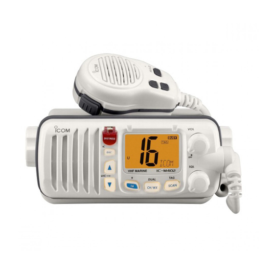
iM402
(REMOTE-CONTROL MIC COMPATIBLE)
VHF MARINE TRANSCEIVER
iM402S
This device complies with Part 15 of the FCC rules. Operation is sub-
ject to the following two conditions: (1) This device may not cause
harmful interference, and (2) this device must accept any interference
received, including interference that may cause undesired operation.
IC-M402
Advertisement
Table of Contents

Related Manuals for Icom IC-M402


Summary of Contents for Icom IC-M402
- Page 1 This device complies with Part 15 of the FCC rules. Operation is sub- ject to the following two conditions: (1) This device may not cause harmful interference, and (2) this device must accept any interference received, including interference that may cause undesired operation. IC-M402...
-
Page 2: Foreword
We want to take a couple of moments of your time to thank you for making your IC-M402/M402S your radio of choice, and hope you agree with Icom’s philosophy of “technology first.” Many hours of research and development went into the design of your IC-M402/M402S. -
Page 3: Important
IMPORTANT READ ALL INSTRUCTIONS before using the transceiver. SAVE THIS INSTRUCTION MANUAL— struction manual contains important operating instructions for the IC-M402/M402S. EXPLICIT DEFINITIONS WORD Personal injury, fire hazard or electric R WARNING shock may occur. Equipment damage may occur. CAUTION If disregarded, inconvenience only. -
Page 4: Cautions
This may pose a fire hazard or result in an electric shock. CAUTION: Changes or modifications to this device, not ex- pressly approved by Icom Inc., could void your authority to operate this device under FCC regulations. NEVER connect the transceiver to a power source of more than 16 V DC or use reverse polarity. -
Page 5: Radio Operator Warning
RADIO OPERATOR WARNING Icom requires the radio operator to meet the FCC Requirements for Radio Frequency Expo- sure.An omnidirectional antenna with gain not greater than 9 dBi must be mounted a minimum W ARN ING of 5 meters (measured from the lowest point of the antenna) vertically above the main deck and all possible personnel. -
Page 6: Table Of Contents
I Transmitting DSC calls ... 13 I DSC individual ID... 16 I Receiving DSC calls ... 16 7 INTERCOM OPERATION (IC-M402 only) ... 19 I Intercom operation... 19 8 SET MODE... 20 – 21 I Set mode programming ... 20 I Set mode items... -
Page 7: Operating Rules
OPERATING RULES I Channel selection ï ï PRIORITIES • Read all rules and regulations pertaining to priorities and keep an up-to-date copy handy. Safety and distress calls take priority over all others. • You should monitor Ch 16 when you are not operating on another channel. -
Page 8: Panel Description
➥ Selects the DSC menu when pushed. (p. 11) ➥ While push and hold [H/L] push [DSC] for 1 sec. to show current position and time. (p. 11) ➥ Push [DSC] for 1 sec. to enter intercom mode. (IC-M402 only, p. 19) -
Page 9: I Function Display
PANEL DESCRIPTION I Function display q TRANSMIT INDICATOR (p. 6) “TX” appears while transmitting. w BUSY INDICATOR (p. 6) “BUSY” appears when receiving a signal or when the squelch opens. e TAG CHANNEL INDICATOR (p. 9) Appears when a tag channel is selected. r CALL CHANNEL INDICATOR “CALL”... -
Page 10: Panel Description .................. 2
EXTENSION CABLE only. IC-M402S has no external microphone speaker jack for connecting HM-127 and OPC-999. PANEL DESCRIPTION optional HM-127 REMOTE CONTROL and OPC-999 MICROPHONE can be connected to IC-M402 ➥ p. 19 Intercom operation ➥ p. 26-37 HM-127 REMOTE-CONTROL MICROPHONE ) -
Page 11: Basic Operation
BASIC OPERATION I Channel selection ï ï Channel 16 Ch 16 is the distress and safety channel. It is used for estab- lishing initial contact with another station and for emergency communications. Channel 16 is monitored during both dual- watch and tri-watch. While standing by, you must monitor Ch 16. ➥... -
Page 12: I Microphone Lock Function
ï ï Weather channels There are 10 weather channels. Used for monitoring weather channels from the NOAA (National Oceanographic and At- mospheric Administration) broadcasts. The transceiver can detect a weather alert tone on the se- lected weather channel while receiving the channel, during standby on a regular channel or while scanning. -
Page 13: Basic Operation ....................... 5
BASIC OPERATION I Call channel programming The call channel is used to select Ch 9, however, you can program your most often-used channels in each channel group for quick recall. q While pushing [H/L], push [CH/WX] one or more times to select the desired channel group (U.S.A., International, Canada) to be programmed. -
Page 14: Dualwatch/Tri-Watch
I Description Dualwatch monitors Ch 16 while you are receiving an-other channel; tri-watch monitors Ch 16 and the call channel while receiving another channel. DUALWATCH/TRI-WATCH SIMULATION Dualwatch Tri-watch • If a signal is received on Channel 16, dualwatch/tri-watch pauses on Ch 16 until the signal disappears. •... -
Page 15: Scan Operations
SCAN OPERATIONS I Setting tag channels For more efficient scanning, add desired channels as tag channels or clear tag channels for unwanted channels. Chan- nels set as non-tag channels will be skipped during scanning. Tag channels can be assigned to each channel group (U.S.A., International, Canada) independently. -
Page 16: I Scan Types
I Scan types Scanning is an efficient way to locate signals quickly over a wide frequency range. The transceiver has priority scan and normal scan. When the weather alert function is in use, the selected weather channel is checked while scanning. (p. 20) PRIORITY SCAN CH 01 CH 02... -
Page 17: Dsc Operation
DSC OPERATION I MMSI code programming The 9-digit MMSI (DSC self ID) code can be programmed at power ON. This function is not available when the MMSI code has been programmed by the dealer. This code programming can be performed only 2 times. q Turn power OFF. -
Page 18: I Distress Call
I Distress call A distress call should be transmitted if, in the opinion of the Master, the ship or a person is in distress and requires imme- diate assistance. • All keys, switches and controllers on the transceiver are functional. NEVER USE THE DISTRESS CALL WHEN YOUR SHIP IS NOT IN AN EMERGENCY. -
Page 19: I Transmitting Dsc Calls
DSC OPERATION I Transmitting DSC calls ï ï Transmitting individual call The individual call function allows you to transmit a DSC sig- nal to a specific party only. q Select a desired channel other than Ch 70. w Push [DSC] to select the DSC menu. e Push [Y]/[Z] to select “individual”... - Page 20 ï ï Transmitting individual acknowledgement Transmit an acknowledgement (‘able to comply’ or ‘unable to comply’) when an individual call for you is received. q “RCV Individual” scrolls. w Push [Y] or [Z] to select the acknowledgement “ABLE” or “UNABLE”. e Push [DSC] to enter selected individ- ual call acknowledgement, “OK”...
- Page 21 DSC OPERATION ï ï Transmitting position request call Transmit a position request call when you want to know your friend’s current position, etc. q Select a desired channel other than Ch 70. w Push [DSC] to select the DSC menu. e Push [Y]/[Z] to select “POS RE- QUEST.”...
-
Page 22: I Dsc Individual Id
I DSC individual ID A total of 30 DSC address ID’s can be programmed and named with up to 10 characters. ï ï Programming address ID q Push [DSC] to select the DSC menu. w Push [Y]/[Z] to select “ADDRESS” and push [DSC]. -
Page 23: I Receiving Dsc Calls
DSC OPERATION I Receiving DSC calls ï ï Receiving a distress call While monitoring Ch 70 and a distress call is received: ➥ Emergency alarm sounds for 2 min- utes. • Push any switch to stop the alarm. ➥ “DSC” appears and “RCV Distress” scrolls in the display, then Ch 16 is automatically selected. -
Page 24: Dsc Operation ....................... 11
ï ï Receiving an individual call While monitoring Ch 70 and an individ- ual call is received: ➥ Emergency alarm or beeps sound de- pending on the received category. ➥“RCV Individual” scrolls in the display, then the channel specified by the calling station is automat- ically selected for checking the channel condition. -
Page 25: Intercom Operation (Ic-M402 Only)
• “TALK” or “LSTN” appears on the caller or listener function dis- play, respectively. •To adjust the IC-M402’s speaker output level, rotate [VOL]. • To adjust the HM-127’s speaker output level, push [Y]/[Z] after pushing [VOL] on the HM-127. -
Page 26: Set Mode
I Set mode programming Set mode is used to change the conditions of some of the transceiver’s functions. Available functions may differ depending on dealer set- • ting. The optional HM-127 has it’s own settings for the beep • tone and LCD contrast. (p. 34) q Turn power OFF. - Page 27 SET MODE ï ï Dual/tri watch This item can be selected as dualwatch or tri-watch. (p. 8) ï ï DSC watch DSC watch monitors Ch 70 while you are receiving an- other channel. If a distress signal is received on Ch 70, the transceiver monitors Ch 16 and Ch 70 alternately until the distress signal disappears.
-
Page 28: Connections And Maintenance
INSTALLATION AND MAINTENANCE I Supplied accessories The following accessories are supplied: q Mounting bracket ... 1 w DC power cable (OPC-891) ... 1 e Microphone hanger ... 1 r Mounting bracket knobs ... 2 × 20 t Mounting screws (5 ) ... -
Page 29: I Connections
I Connections q DC POWER CONNECTOR Connects the supplied DC power cable from this connector to an external 12 V battery. w EXTERNAL MICROPHONE JACK (IC-M402 only) Connects to optional HM-127 PHONE e ANTENNA CONNECTOR Connects a marine VHF antenna with a PL-259 connector to the transceiver. -
Page 30: I Mounting The Transceiver
I Mounting the transceiver ï ï Using the supplied mounting bracket The universal mounting bracket supplied with your transceiver allows overhead or dashboard mounting. • Mount the transceiver securely with the 2 supplied screws (M5 x 20) to a surface which is more than 10 mm thick and can support more than 5 kg. -
Page 31: I Mb-69 Mounting Bracket (Option)
Tighten the locking nuts (rotate counterclockwise) so that the transceiver is securely mounted in position as below. y Connect the antenna and control cable, then return the in- strument control panel to its original place. IC-M402... -
Page 32: Remote-Control Microphone (Ic-M402 Only)
HM-127 REMOTE-CONTROL MICROPHONE OPTIONAL (IC-M402 only) I Panel description The optional HM-127 remotely controls the IC-M402 and pro- vides an optional intercom function. Speaker q POWER SWITCH [PWR] (p. 29) Push for 2 sec. to turn the HM-127 power ON or OFF when the IC-M402 power is turned ON. - Page 33 ATTENUATOR/INTERCOM/SCRAMBLER SWITCH [LO/DX•IC•SCR] ➥ Activates the intercom function when pushed for 1 sec. (pgs. 19, 34) Calls the IC-M402 when pushed and held while in inter- • com mode. NOTE: RF attenuator and voice scrambler are not available for IC-M402.
-
Page 34: I Function Display
I Function display TX BUSY CALL WX ALT P SCAN TRI q CHANNEL GROUP INDICATOR (pgs. 6, 31) Indicates whether an International (INT), U.S.A. (USA) or Canadian (CAN) channel is selected. w KEY LOCK INDICATOR (p. 30) ➥ Appears while the key lock function is in use. ➥... -
Page 35: I Receiving And Transmitting
HM-127 REMOTE-CONTROL MICROPHONE !2 WEATHER CHANNEL INDICATOR (pgs. 6, 31) ➥“WX” appears when a weather channel is selected. ➥ “ALT” appears when the weather alert function is in use; flashes when an alert tone is received. !3 LOW POWER INDICATOR (pgs. 6, 29) Appears when low power is selected. -
Page 36: I Lock Functions
t Push and hold [PTT] to transmit, then speak into the mi- crophone. • “ ” appears. • Ch 70 cannot be used for transmission (for GMDSS use). Simplex channels, 3, 21, 23, 61, 64, 81, 82 and 83 CAN- NOT be lawfully used by the general public in U.S.A. -
Page 37: I Channel Selection
HM-127 REMOTE-CONTROL MICROPHONE I Channel selection ï ï Channel 16 q Push [16] to select Ch 16. w Push [CH/WX] to return to the condition before selecting Chan- nel 16, or push [Y] or [Z] to se- lect operating channel. ï... -
Page 38: I Display Backlighting
I Display backlighting The function display and switches can be backlit for better visibility under low light conditions. And the backlighting con- dition can be adjusted independently from the transceiver. q Push [VOL•DIM] for 1 sec. to enter backlight adjusting mode. -
Page 39: I Starting A Scan
HM-127 REMOTE-CONTROL MICROPHONE I Starting a scan q Push [CH/WX•U/I/C] several times while pushing [H/L] to select the channel group (USA, INT, CAN), if desired. • When the weather alert function is in use, select the desired weather channel with [CH/WX] and [Y]/[Z]. w Push [SCN] to start priority or normal scan. -
Page 40: I Set Mode Programming
I Set mode programming Set mode is used to change the condition of the transceiver’s functions and the microphone’s own functions: In this section, instructions are for the microphone’s own func- tions only. Refer p. 30–33 for the setting of the other func- tions. -
Page 41: I Channel Names
HM-127 REMOTE-CONTROL MICROPHONE I Channel names q Push [Y]/[Z] to select a channel to program. • Push [CH/WX•U/I/C] several times while pushing [H/L] to select the channel group (USA, INT, CAN), if desired. w While push and hold [H/L] push [16•9]. •... -
Page 42: I Installation
I Installation The optional HM-127 can be connected to the IC-M402 di- rectly, as well as via the supplied connection cable for longer distance remote operation. The connector of the connection cable can be installed into a cabinet, wall, etc., as a built-in plug. - Page 43 HM-127 REMOTE-CONTROL MICROPHONE Gasket...
-
Page 44: Troubleshooting
PROBLEM POSSIBLE CAUSE No power comes ON. Bad connection to the power supply. No sound comes from Squelch level is too deep. the speaker. Volume level is too low. Speaker has been exposed to water. Transmitting is impossi- Some channels are for low power or ble, or high power can- receive only. -
Page 45: Channel List
CHANNEL LIST Channel number Frequency (MHz) CAN Transmit Receive 156.050 160.650 156.050 156.050 156.100 160.700 156.150 160.750 156.150 156.150 156.200 160.800 04A 156.200 156.200 156.250 160.850 05A 156.250 156.250 156.300 156.300 156.350 160.950 07A 156.350 156.350 156.400 156.400 156.450 156.450 156.500 156.500 156.550 156.550 156.600 156.600... -
Page 46: Specifications
I Specifications ï ï General • Frequency coverage Transmit 156.025–157.425 MHz Receive 156.050–163.275 MHz • Mode : FM (16K0G3E) DSC(16K0G2B) • Channel spacing : 25 kHz • Current drain (at 13.8 V) : Tx 6.0 A (at 25 W output). Rx 1.2 A (at AF max.) •... -
Page 47: I Dimensions
SPECIFICATIONS I Dimensions... -
Page 48: Mb-69/Hm-127 Template
MB-69/HM-127 TEMPLATE HM-127 MB-69 Unit: mm (inch) -
Page 49: Options
External microphone-type controller. Provides optional inter- com operation. 6 m (20 feet) microphone cable and mount- ing base included. Black and white colours are available. *IC-M402 only • OPC-999* MICROPHONE EXTENSION CABLE 6 m (20 feet) microphone extension cable for optional HM- 127. - Page 50 Count on us! A-6137H-1US Printed in Japan 1-1-32 Kamiminami, Hirano-ku, Osaka 547-0003 Japan © 2002 Icom Inc.