Advertisement
Quick Links
NOTE:
Please read all instructions
carefully before using this
product
Table of Contents
Safety Notice
Hardware Identifier
Assembly Instruction
Parts List
Resistance Chart
Warranty
Ordering Parts
Model
IVT-845
Retain This
Manual for
Reference
10-30-08
OWNER'S
MANUAL
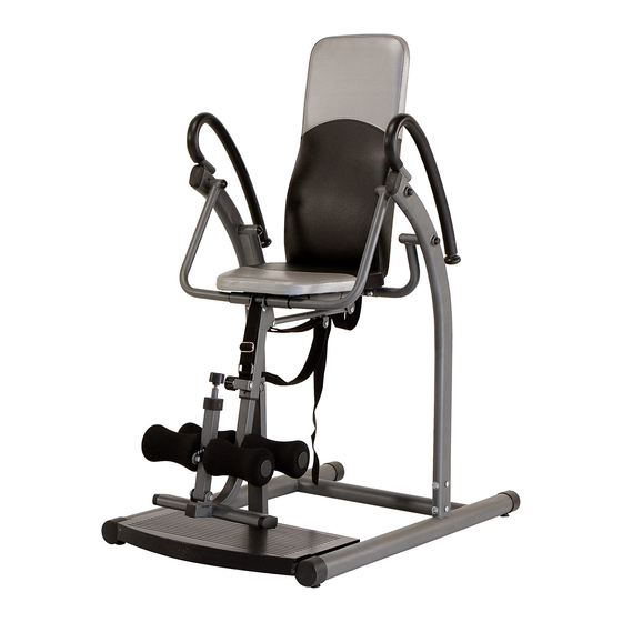
INVERSION CHAIR
14777 DON JULIAN RD., CITY OF INDUSTRY, CA 91746
Tel: (800) 999-8899 Fax: (626) 961-9966
www.impex-fitness.com
info@impex-fitness.com
MARCY
IVT-845
®
IMPEX
INC.
Advertisement

Related Manuals for Impex MARCY IVT-845


Summary of Contents for Impex MARCY IVT-845
- Page 1 NOTE: Please read all instructions carefully before using this product Table of Contents Safety Notice MARCY Hardware Identifier INVERSION CHAIR Assembly Instruction Parts List IVT-845 Resistance Chart Warranty Ordering Parts Model IVT-845 Retain This Manual for Reference 10-30-08 OWNER'S ®...
-
Page 2: Table Of Contents
ORDERING PARTS..................………… 16 BEFORE YOU BEGIN ® Thank you for selecting the Marcy Inversion Chair IVT-845 by IMPEX FITNESS PRODUCTS. For your safety and benefit, read this manual carefully before using the machine. As a manufacturer, we are committed to provide you complete customer satisfaction. If you have any questions, or find there are missing or damaged parts, we guarantee you complete satisfaction through direct assistance from our factory. -
Page 3: Important Safety Notice
IMPORTANT SAFETY NOTICE PRECAUTIONS This exercise machine is built for optimum safety. However, certain precautions apply whenever you operate a piece of exercise equipment. Be sure to read the entire manual before you assemble or operate your machine. In particular, note the following safety precautions: 1. - Page 4 WARNING LABEL REPLACEMENT The warning label shown here has been placed on the Base Frame. If the label is missing or illegible, please call customer service at 1-800-888-8899 for replacements. Apply the label in the location shown.
-
Page 5: Hardware Pack
HARDWARE PACK #3 M8 x 2 ½” Allen Bolt (Qty 2) #4 Ø 5/8” Washer (Qty 16) #5 M8 Aircraft Nut (Qty 5) #6 Ø ¾” Washer (Qty 5) #7 M10 Aircraft Nut (Qty 5) #10 M8 x 5/8” Allen Bolt (Qty 16) #11 Ø... -
Page 6: Assembly Instruction
ASSEMBLY INSTRUCTION Tools Required for Assembling the Machine: Two Adjustable Wrenches, two Allen Wrenches, and one Philips Screwdriver. NOTE: It is strongly recommended that this machine to be assembled by two or more people to avoid possible injury. STEP 1 (See Diagram 1) A.) Place the Base Frame (#1) on flat floor. - Page 7 STEP 2 (See Diagram 2) A.) Two people to assemble this step are highly recommended. Do not tighten the Bolts until instructed to do so. B.) Attach the pivots on the Rear Left & Right Support Tube (#40) & (#41) to the back holes on the Left &...
- Page 8 STEP 3 (See Diagram 3) A.) Two people to assemble this step are highly recommended. Do not tighten Nuts and Bolts until instructed to do so. B.) Attach the Left & Right Support (#8) & (#9) onto the open bracket one the Base Frame (#1). Make sure the Front Support Base (#47) is placed in front of the Front Vertical Frame (#2).
- Page 9 STEP 4 (See Diagram 4) A.) Attach the 1 5/8” Rubber Bumper (#29) to the Foot Support (#19). Attach the ¾” Rubber Bumper (#30) to the 1 5/8” Rubber Bumper (#29). B.) Secure them together to the Foot Support with one M6 x 2 ½” Philips Screw (#31). DIAGRAM 4 STEP 5 (See Diagram 5)
- Page 10 A.) Pull the Foot Support Lock Knob (#20) and then insert the Foot Support (#19) into the Foot Support Base (#47) from bottom. Release the Lock Knob and lock the Foot Support at desired position. DIAGRAM 5...
- Page 11 STEP 6 (See Diagram 6) A.) Attach the pivot on the bottom of Foot Lock Frame (#21) to the open bracket on the Foot Support (#19). Secure it with one M8 x 2 3/8” Allen Bolt (#17), two Ø ¾” Washers (#4), and one M8 Aircraft Nut (#5).
- Page 12 STEP 7 (See Diagram 7) A.) Pull up the Foot Lock Knob (#23). Insert the Foot Lock Adjustment (#24) through the opening on Foot Lock (#21) to the opening on the Foot Support (#19). Note: The ratchet on the Foot Lock Adjustment needs to be in the opening on Foot Lock Frame.
- Page 13 STEP 8 (See Diagram 8) A.) Push four Foam Rolls (#26) onto the tubes on the Foot Support (#19) and Inversion Foot Lock (#21). Plug four Foam Roll End Caps (#27) into the tube ends. DIAGRAM 8...
- Page 14 STEP 9 (See Diagram 9) A.) Insert the Backrest Support (#34) into the back of Backrest Board (#28) into the Rear Vertical Frame (#22). Secure it with four M8 x 5/8” Allen Bolts (#10) and four Ø 5/8” Washers (#4). DIAGRAM 9...
-
Page 15: Exploded Diagram
EXPLODED DIAGRAM... -
Page 16: Parts List
PARTS LIST KEY NO. DESCRIPTION Q’ty Base Frame Swing Frame Front Vertical Frame Foot Support Base M8 x 2 ½” Allen Bolt Connect Tube Ø 5/8” Washer Ø 5/8” x 3/8” Bushing M8 Aircraft Nut M6 x 2 1/8” Allen Bolt Ø... -
Page 17: Limited Warranty
® IMPEX INC. LIMITED WARRANTY ® IMPEX Inc. ("IMPEX ") warrants this product to be free from defects in workmanship and material, under normal use and service conditions, for a period of two years on the Frame from the date of purchase. This warranty extends only to the original purchaser. IMPEX's obligation under this Warranty is limited to replacing or repairing, at IMPEX's option.